1995 NISSAN ALMERA N15 adding oil
[x] Cancel search: adding oilPage 222 of 1701

PRECAUTIONS
Service Notice
• When removing orinstalling variousparts,placeacloth orpadding ontothevehicle bodytoprevent
scratches.
• Handle trim,molding, instruments, grille,etc.carefully duringremoving orinstalling. Becareful not
to soil ordamage them.
• Apply sealing compound wherenecessary wheninstalling parts.
• When applying sealingcompound, becareful thatthesealing compound doesnotprotrude from
parts.
• When replacing anymetal parts(forexample bodyouter panel, members, etc.),besure totake rust
prevention measures.
SupplementalRestraintSystem(SRS)"AIR
BAG" (DualAirBag System)
The Supplemental RestraintSystem"AirBag", usedalong withaseat belt,helps toreduce therisk or
severity ofinjury tothe driver andfront passenger inafrontal collision. TheSupplemental Restraint
System consists ofair bag modules (locatedinthe center ofthe steering wheelandonthe instrument
panel onthe passenger side),adiagnosis sensorunit,warning lamp,wiring harness andspiral cable.
Information necessarytoservice thesystem safelyisincluded inthe
RSsection
ofthis Service Manual.
WARNING:
• Toavoid rendering theSRS inoperative, whichcouldincrease therisk ofpersonal injuryordeath
in the event ofacollision whichwould resultinair bag inflation, allmaintenance mustbeperformed
by an authorized NISSANdealer.
• Improper maintenance, includingincorrectremovalandinstallation ofthe SRS, canlead topersonal
injury caused byunintentional activationofthe system.
• Donot use electrical testequipment onany circuit related tothe SRS unless instructed tointhis
Service Manual. SRSwiring harnesses arecovered withyellow insulation eitherjustbefore the
harness connectors orfor the complete harness,foreasy identification.
Supplemental RestraintSystem(SRS)"AIR
BAG" (Single AirBag System)
The Supplemental RestraintSystem"AirBag", usedalong withaseat belt,helps toreduce therisk or
severity ofinjury tothe driver inafrontal collision. TheSupplemental RestraintSystemconsists ofan
air bag module (located inthe center ofthe steering wheel),adiagnosis sensorunit,warning lamp,
wiring harness andspiral cable. Information necessarytoservice thesystem safelyisincluded inthe
RS section
ofthis Service Manual.
WARNING:
• Toavoid rendering theSRS inoperative, whichcouldincrease therisk ofpersonal injuryordeath
in the event ofacollision whichwould resultinair bag inflation, allmaintenance mustbeperformed
by an authorized NISSANdealer.
• Improper maintenance, includingincorrectremovalandinstallation ofthe SRS, canlead topersonal
injury caused byunintentional activationofthe system.
• Donot use electrical testequipment onany circuit related tothe SRS unless instructed tointhis
Service Manual.
BT-2
Page 225 of 1701

BODYEND
Body Front End
• When removing orinstalling hood,placeacloth orother padding onhood. Thisprevents vehiclebody
from being scratched.
• Bumper fasciaismade ofplastic. Donot use excessive forceandbesure tokeep oilaway fromit.
• Hood adjustment: Adjustathinge portion.
• Hood lockadjustment: Afteradjusting, checkhoodlockcontrol operation. Applyacoat ofgrease to
hood locks engaging mechanism.
• Hood opener: Donot attempt tobend cable forcibly. Doingsoincreases effortrequired tounlock
hood.
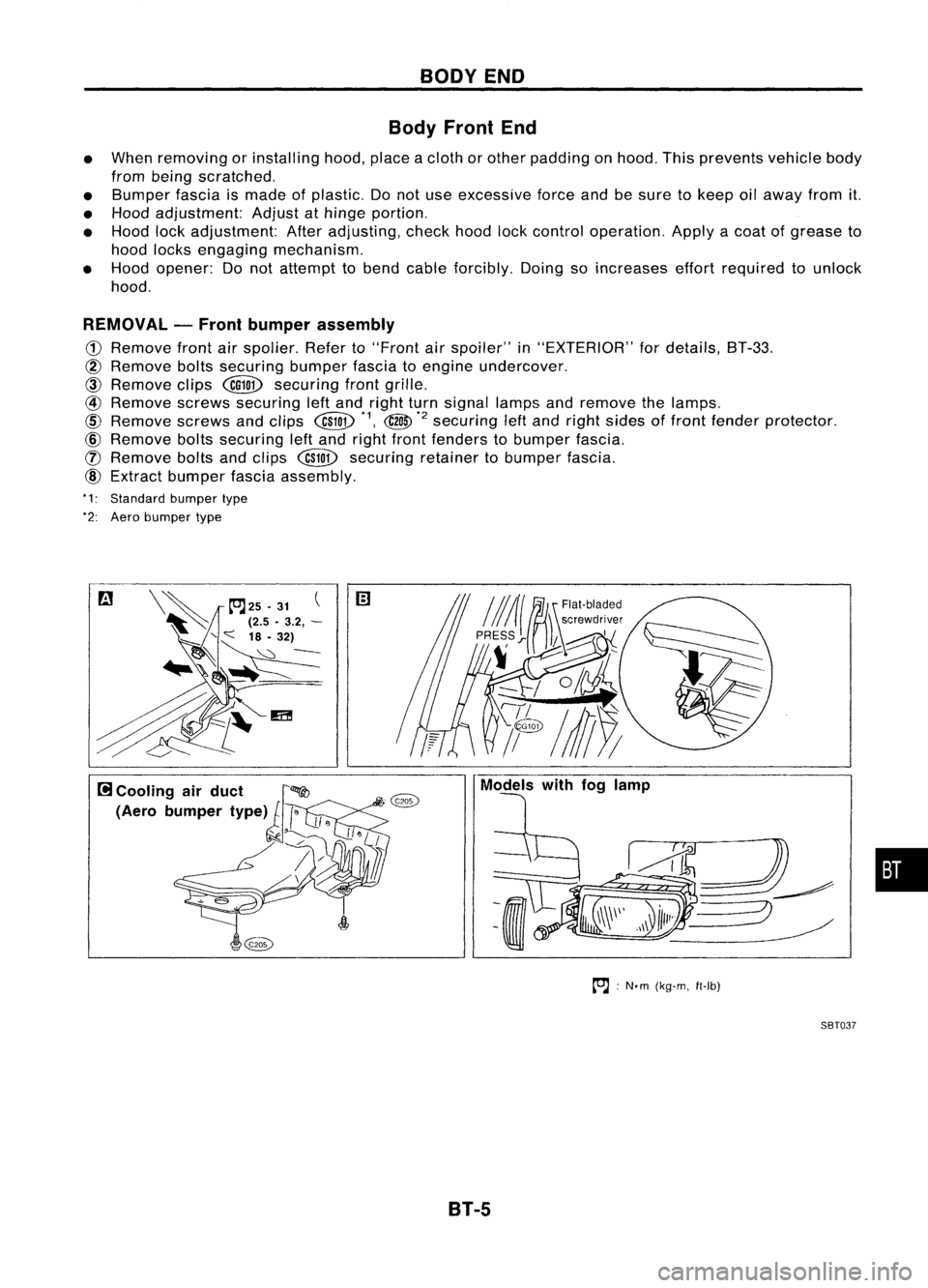
REMOVAL -Front bumper assembly
CD
Remove frontairspolier. Referto"Front
air
spoiler" in"EXTERIOR" fordetails, BT-33.
@
Remove boltssecuring bumperfasciatoengine undercover.
CID
Remove clips
@QD
securing frontgrille.
@
Remove screwssecuring leftand right turnsignal lampsandremove thelamps.
@
Remove screwsandclips
@W
*1,
@
*2
securing
leftand right sides offront fender protector.
@)
Remove boltssecuring leftand right front fenders tobumper fascia.
([) Remove boltsandclips
@W
securing retainertobumper fascia.
@)
Extract bumper fasciaassembly.
*1: Standard bumpertype
*2: Aero bumper type
to.J:
N'm (kg-m, ft-Ib)
SBT037
B1-5
•
Page 227 of 1701

BODYEND
Body RearEndandOpener
4-DOOR SEDAN
• When removing orinstalling trunklid,place acloth orother padding onrear fender. Thisprevents
vehicle bodyfrombeing scratched.
• Bumper fasciaismade ofplastic. Donot use excessive forceandbesure tokeep oilaway fromit.
• Trunk lidadjustment: Adjustathinge-trunk lidportion forproper trunklidfit.
• Trunk lidlock system adjustment: Adjuststriker sothat itis inthe center ofthe lock. After
adjustment, checktrunklidlock operation.
• Opener cable:Donot attempt tobend cable usingexcessive force.
• After installation, makesurethattrunk lidand fuel filler lidopen smoothly.
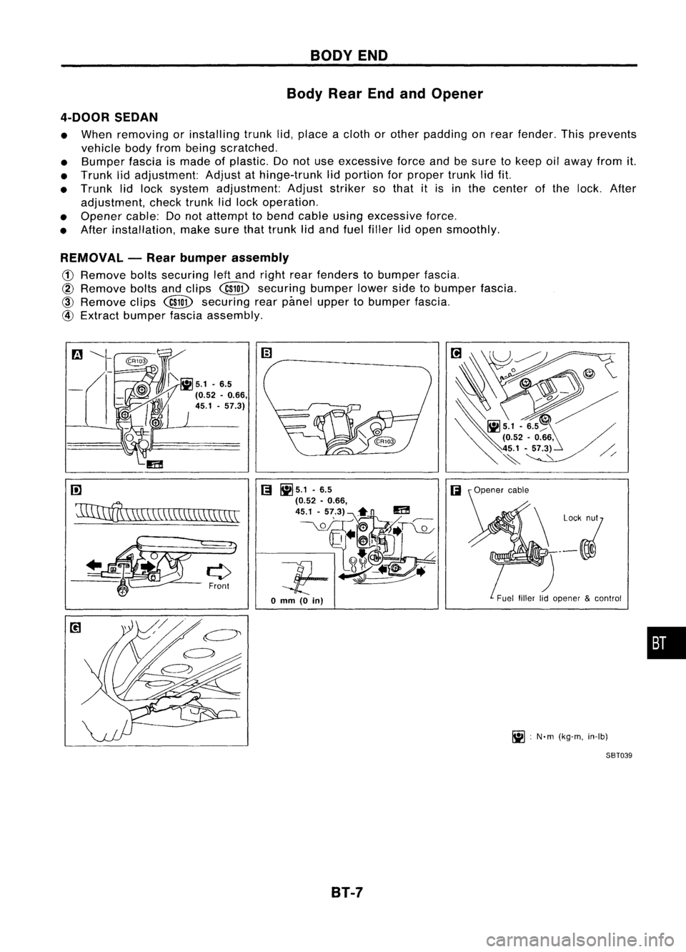
REMOVAL -Rear bumper assembly
CD
Remove boltssecuring leHand right rearfenders tobumper fascia.
@
Remove boltsandclips
@ID
securing bumperlowersidetobumper fascia.
@
Remove clips
@ID
securing rearpimel upper tobumper fascia.
@
Extract bumper fasciaassembly.
rn
'11IInff\
\W,\\CC\\\\\\\\\\\\\\
[;I
~5.1 .6.5
(;I
(0.52 •0.66,
45.1 -57.3)~n
m
__ \.QL_OIT~~T~
Jf-~~
o
mm
(0
in)
B1-7 Fuel
fillerlidopener &control
~ :N'm (kg-m, in-Ib)
SBT039
•
Page 1194 of 1701

COMPRESSIONPRESSURE
20
mm
(O.79 In)dls.
Use compressor testerwhose end(rubber
portion) isless than 20mm (0.79 in)dia.
Otherwise, itmay becaught bycylinder
head during removal.
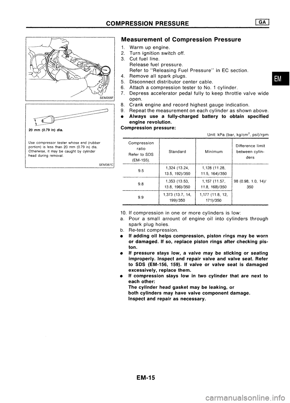
SEM387CMeasurement
ofCompression Pressure
1. Warm upengine.
2. Turn ignition switchoff.
3. Cut fuel line.
Release fuelpressure.
Refer to"Releasing FuelPressure" inEC section. •
4. Remove allspark plugs.
5. Disconnect distributorcentercable.
6. Attach acompression testertoNO.1 cylinder.
7. Depress accelerator pedalfullytokeep throttle valvewide
open.
8. Crank engine andrecord highest gaugeindication.
9. Repeat themeasurement oneach cylinder asshown above.
• Always useafully-charged batterytoobtain specified
engine revolution.
Compression pressure:
Unit:kPa(bar, kg/cm
2,
psi)/rpm
Compression Differencelimit
ratio
Standard
Refer toSOS Minimum
betweencylin-
(EM-155). ders
9.5 1,324
(13.24, 1,128(11.28,
13.5, 192)/350 11.5,164)/350
9.8 1,353
(1353, 1,157(11.57, 98(0.98, 1.0,14)/
13.8, 196)/350 11.8,168)/350
350
9.9 1,373
(13.7, 14, 1,177(11.8,12,
199)/350 171)/350
10.
If
compression inone ormore cylinders islow:
a. Pour asmall amount ofengine oilinto cylinders through
spark plugholes.
b. Re-test compression,
• Ifadding oilhelps compression, pistonringsmaybeworn
or damaged. Ifso, replace pistonringsafterchecking pis-
ton.
• Ifpressure stayslow,avalve maybesticking orseating
improperly. Inspectandrepair valveandvalve seat.Refer
to SOS (EM-156, 159).Ifvalve orvalve seatisdamaged
excessively, replacethem.
• Ifcompression stayslowintwo cylinder thatarenext to
each other:
The cylinder headgasket maybeleaking, or
both cylinders mayhave valve component damage.
Inspect andrepair asnecessary.
EM-15
Page 1241 of 1701

COMPRESSIONPRESSURE
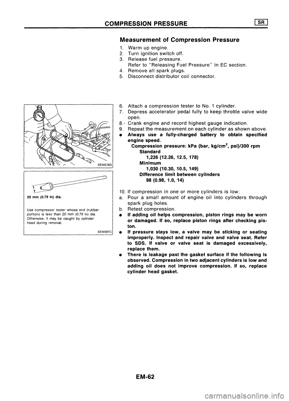
Measurement ofCompression Pressure
1. Warm upengine.
2. Turn ignition switchoff.
3. Release fuelpressure.
Refer to"Releasing FuelPressure" inEC section.
4. Remove allspark plugs.
5. Disconnect distributorcoilconnector.
20
mm (0.79
In)dls.
Use compressor testerwhose end(rubber
portion) isless than 20mm (0.79 in)dia.
Otherwise. itmay becaught bycylinder
head during removal.
SEM387C6.
Attach acompression testertoNO.1 cylinder.
7. Depress accelerator pedalfullytokeep throttle valvewide
open.
8.' Crank engine andrecord highest gaugeindication.
9. Repeat themeasurement oneach cylinder asshown above.
• Always useafully-charged batterytoobtain specified
engine speed.
Compression pressure:kPa(bar, kg/cm
2,
psi)/300 rpm
Standard 1,226 (12.26, 12.5,178)
Minimum 1,030 (10.30, 10.5,149)
Difference limitbetween cylinders
98 (0.98, 1.0,14)
10. Ifcompression inone ormore cylinders islow:
a. Pour asmall amount ofengine oilinto cylinders through
spark plugholes.
b. Retest compression.
• If
adding oilhelps compression, pistonringsmaybeworn
or damaged.
If
so, replace pistonringsafterchecking pis-
ton.
• Ifpressure stayslow,avalve maybesticking orseating
improperly. Inspectandrepair valveandvalve seat.Refer
to
50S.
If
valve orvalve seatisdamaged excessively,
replace them.
• There isleakage pastthegasket surface ifthe following is
observed. Compression intwo adjacent cylinders islow and
adding oildoes notimprove compression.
If
so, replace
cylinder headgasket.
EM-62