1995 NISSAN ALMERA N15 wheel
[x] Cancel search: wheelPage 7 of 1701

PREPARATIONANDPRECAUTIONS
Service Notice
Supplemental RestraintSystem(SRS)"AIR
BAG" (DualAirBag System)
The Supplemental RestraintSystem"AirBag" usedalong withaseat belt, helps toreduce therisk or
severity ofinjury tothe driver andfront passenger inafrontal collision. TheSupplemental Restraint
System consists ofair bag modules (locatedinthe center ofthe steering wheelandonthe instrument
panel onthe passenger side),adiagnosis sensorunit,warning lamp,wiring harness andspiral cable.
Information necessarytoservice thesystem safelyisincluded inthe
RSsection
ofthis Service Manual.
WARNING:
• Toavoid rendering theSRS inoperative, whichcouldincrease therisk ofpersonal injuryordeath
in the event ofacollision whichwould resultinair bag inflation, allmaintenance mustbeperformed
by an authorized NISSANdealer.
• Improper maintenance, includingincorrectremovalandinstallation ofthe SRS, canlead topersonal
injury caused byunintentional activationofthe system.
Ii
Donot use electrical testequipment onany circuit related tothe SRS unless instructed tointhis
Service Manual. SRSwiring harnesses arecovered withyellow insulation eitherjustbefore the
harness connectors orfor the complete harness,foreasy identification.
•
Before proceeding withdisassembly, thor-
oughly cleantheoutside ofthe transaxle. Itis
important toprevent theinternal partsfrom
becoming contaminated bydirt orother for-
eign matter.
• Disassembly shouldbedone inaclean work
area.
• Use lint-free clothortowels forwiping parts
clean. Common shopragscanleave fibers
that could interfere withtheoperation ofthe
transaxle.
• Place disassembled partsinorder, onaparts
rack, foreasier andproper assembly.
• Allparts should becarefully cleaned-witha
general purpose, non-flammable solvent
before inspection orreassembly.
• Gaskets, sealsandO-rings shouldbe
replaced anytime thetransaxle isdisassem-
bled.
• Itis very important toperform functional tests
whenever theyareindicated. •
The valve bodycontains precision partsand
requires extremecarewhen partsare
removed andserviced. Placedisassembled
valve bodyparts inorder, onaparts rack,for
easier andproper assembly. Carewillalso
prevent springs andsmall partsfrombecom-
ing scattered orlost.
• Properly installedvales,sleeves, plugs,etc.
will slide along theirbores inthe valve body
under theirownweight.
• Before assembly, applyacoat ofrecom-
mended ATFtoall parts. Apply petroleum
jelly toprotect O-ringandseals, orhold bear-
ings andwashers inplace during assembly.
Do not use grease.
• Extremely careshould betaken toavoid dam-
age toO-rings, sealsandgaskets when
assembling.
• After overhaul, refillthetransaxle withnew
ATF.
•
Supplemental RestraintSystem(SRS)"AIR
BAG" (Single AirBag System)
The Supplemental RestraintSystem"AirBag" andused along withaseat belt,helps toreduce therisk
or severity ofinjury tothe driver inafrontal collision. TheSupplemental RestraintSystemconsists of
an air bag module (located inthe center ofthe steering wheel),adiagnosis sensorunit,warning lamp,
wiring harness andspiral cable. Information necessarytoservice thesystem safelyisincluded inthe
RS section
ofthis Service Manual.
WARNING:
• Toavoid rendering theSRS inoperative, whichcouldincrease therisk ofpersonal injuryordeath
in the event ofacollision whichwould resultinair bag inflation, allmaintenance mustbeperformed
by an authorized NISSANdealer.
• Improper maintenance, includingincorrectremovalandinstallation ofthe SRS, canlead topersonal
injury caused byunintentional activationofthe system.
• Donot use electrical testequipment onany circuit related tothe SRS unless instructed tointhis
Service Manual.
AT-7
Page 24 of 1701
TROUBLEDIAGNOSES
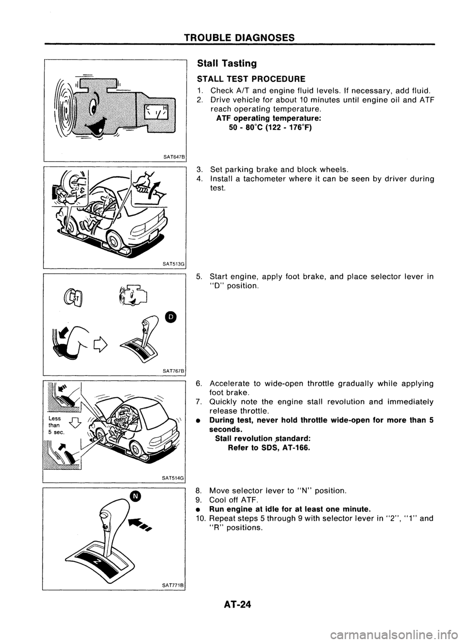
Stall Tasting
STALL TESTPROCEDURE
1. Check
AIT
and engine fluidlevels. Ifnecessary, addfluid.
2. Drive vehicle forabout 10minutes untilengine oiland ATF
reach operating temperature.
ATF operating temperature:
50 -80
0
e (122-176°F)
SAT6478
3.Set parking brakeandblock wheels.
4. Install atachometer whereitcan beseen bydriver during
test.
SAT513G 5.
~ ~ID
•
~c;>
SAT7678
Start
engine, applyfootbrake, andplace selector leverin
"0"
position.
6. Accelerate towide-open throttlegradually whileapplying
foot brake.
7. Quickly notetheengine stallrevolution andimmediately
release throttle.
• During test,never holdthrottle wide-open formore than5
seconds. Stall revolution .standard:
Refer toSDS, AT-166.
SAT514G
8.Move selector leverto"N" position.
9. Cool offATF.
• Run engine atidle foratleast oneminute.
10. Repeat steps5through 9with selector leverin"2", "1"and
"R
n
positions.
SAT7718 AT-24
Page 26 of 1701
TROUBLEDIAGNOSES
Pressure Testing
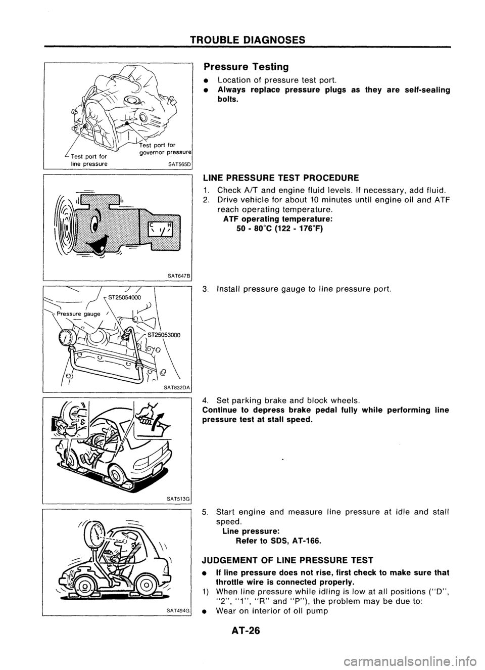
• Location ofpressure testport.
• Always replace pressure plugsasthey areself-sealing
bolts.
Test portfor
line pressure governor
pressure
SAT565D
LINEPRESSURE TESTPROCEDURE
1. Check AfTand engine fluidlevels. Ifnecessary, addfluid.
2. Drive vehicle forabout 10minutes untilengine oiland ATF
reach operating temperature.
ATF operating temperature:
50 -80°C (122-176°F)
SAT647B
3.Install pressure gaugetoline pressure port.
4. Set parking brakeandblock wheels.
Continue todepress brakepedalfullywhile performing line
pressure testatstall speed.
SAT513G
5.Start engine andmeasure linepressure atidle and stall
speed. Line pressure:
Refer toSOS, AT-166.
JUDGEMENT OFLINE PRESSURE TEST
• Ifline pressure doesnotrise, firstcheck tomake surethat
throttle wireisconnected properly.
1) When linepressure whileidling
is
low atall positions ("D",
"2", "1", "R"and"P"), theproblem maybedue to:
SAT494G •
Wear oninterior ofoil pump
AT-26
Page 27 of 1701
'-)
(
~)o
Front
SAT498GTROUBLE
DIAGNOSES
Pressure Testing(Cont'd)
• Oilleakage ator around oilpump, control valvebody, trans-
mission caseorgovernor
• Sticking pressure regulator valve
• Sticking pressure modifiervalve
2) When linepressure whileidling islow ataparticular
position, checkthefollowing.
• Ifoil leaks ator around low
&
reverse brakecircuit, line
pressure becomes lowin"R" position. Butline pressure is
normal in"P", "D", "2"or"1" position.
3) When linepressure ishigh while idling, pressure regulator
valve mayhave stuck.
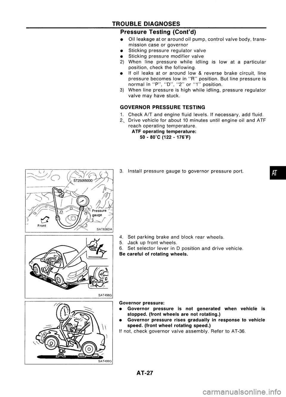
GOVERNOR PRESSURETESTING
1. Check
AIT
and engine fluidlevels. Ifnecessary, addfluid.
2 .. Drive vehicle forabout 10minutes untilengine oiland ATF
reach operating temperature.
ATF operating temperature:
50 -80°C (122-176°F)
3. Install pressure gaugetogovernor pressureport.
4. Set parking brakeandblock rearwheels.
5. Jack upfront wheels.
6. Set selector leverinDposition anddrive vehicle.
Be careful ofrotating wheels.
•
Governor pressure:
• Governor pressureisnot generated whenvehicle is
stopped. (frontwheels arenotrotating.)
• Governor pressurerisesgradually inresponse tovehicle
speed. (frontwheel rotating speed.)
If not, check governor valveassembly. RefertoAT-36.
AT-27
Page 176 of 1701
~~~~~~~~_GENERALJNFORM~ION~~~~~~~~_
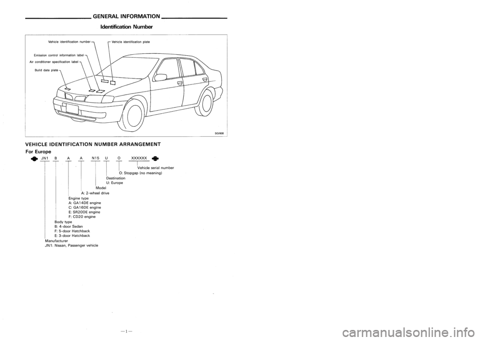
IdentificationNumber _
REPLACEMENTOPERATIONS
Rear SideMember Extension
Sedan
-------
/
/\
---
/ \ -
'------- /~ ,,\I
c-
~ ~>~
111
114
Service
Joint
SGI908
Vehicle
identification plate
A
A
Vehicle
identification number
N15 U
0
xxxxxx.
T
T
---c::
serialnumber
0:
Stopgap (nomeaning)
Destination
U: Europe
Model
A: 2-wheel drive
Engine type
A: GA 14DE engine
C: GA 16DE engine
E: SR20DE engine
F: CD20 engine
Body type
B: 4-door Sedan
F: 5-door Hatchback
E: 3-door Hatchback
Manufacturer
J
N 1: Nissan, Passenger vehicle
Emission
controlinformation label
VEHICLE IDENTIFICATION NUMBERARRANGEMENT
For Europe
• JN1 B
2-spotwelds 3-spotwelds M.I.G plug weld
(For 3panels plugweld method )
d
r;==
dA~ dB~
GTJ ~
M.
I.G seam weld/
Point weld
-1-
-44-
Page 177 of 1701
REPLACEMENTOPERATIONS
Rear Floor Rear ________
GENERALINFORMATION _
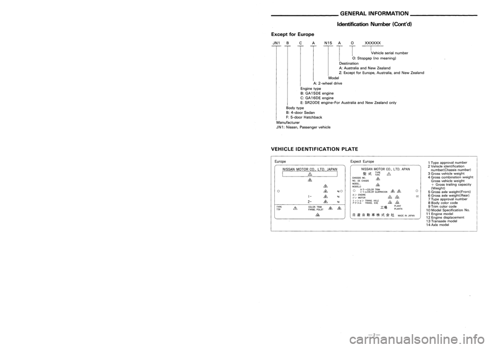
Identification Number(Cont'd)
(Work afterrearpanel havebeen removed.)
ExceptforEurope
IN 1 .B CAN 15A
0
XXXXXX
T
T
--c:::
serialnumber
0:
Stopgap (nomeaning)
Destination
A: Australia andNew Zealand
Z: Except forEurope, Australia, andNew Zealand
Model
A: 2-wheel drive
Engine type
B: GA 15DE engine
C: GA 16DE engine
E: SR20DE engine-For AustraliaandNew Zealand only
Body type
B: 4-door Sedan
F: 5-door Hatchback
Manufacturer
IN 1:Nissan, Passenger vehicle
VEHICLE IDENTIFICATION PLATE
1Type approval number
2 Vehicle identification
number(Chassis number)
3 Gross vehicle weight
4 Gross combination weight
Gross vehicle weight
+
Gross trailing capacity
(Weight)
5 Gross axleweight(Front)
6 Gross axleweight(Rear)
7 Type approval number
8 Body colorcode
9 Trim color code
10 Model Specification No.
11 Engine model
12 Engine displacement
13 Transaxle model
14 Axle model
cc
o
PLANT
PlANTA
El
ii:
13IJJ
if[
**
it~
*1
MADEINJAPAN
NISSAN
MOTORCO.,LTD. APAN
~ tt
~(:l
&
~~~sg~
CNHOA"SIS ~
~~~~~o
&
o ~
0
:ggtg~
~~~RNICION ~
&.
~~ ~~~~~ &
£
; ;~)~ /~~~~~'. AE~~
A1L11
Expect
Europe
~
&
kgO
1-
&
kg
2-
&
kg
COlOR. TRIM
~
&
FARBE. POlST
&
NISSAN
MOTORCO.,LTD. JAPAN
I ~ I
~
o
TYPE
TTP
Europe
FR
_2
3D
HI
B:3door hatchback
5D
HI
B:5door hatchback
Service
Joint
111
~
2-spot welds 3-spotwelds M.
I.
G plug weld .MIG seam weld/
(For 3panels plugweld method )P:
F
weld
• rr=- •
A
===-=
.'S~
.L.LLL
GTJ --- ~
-43-
-2-
Page 184 of 1701
Undercoating REPLACEMENT
OPERATIONS
Front Pillar
(Work afterhoodledge reinforcement hasbeen removed.)
116
1lIl..
(Dri pchannel)
an
(Outer)
112
c;;;;?
FR
112
112
116
Unit:mm
<:=i
FR
1lIl..
( Inner)
112
~
113 :::::-----
Service
Joint
~I!!!!!!!!iiii!!!!!i!II :
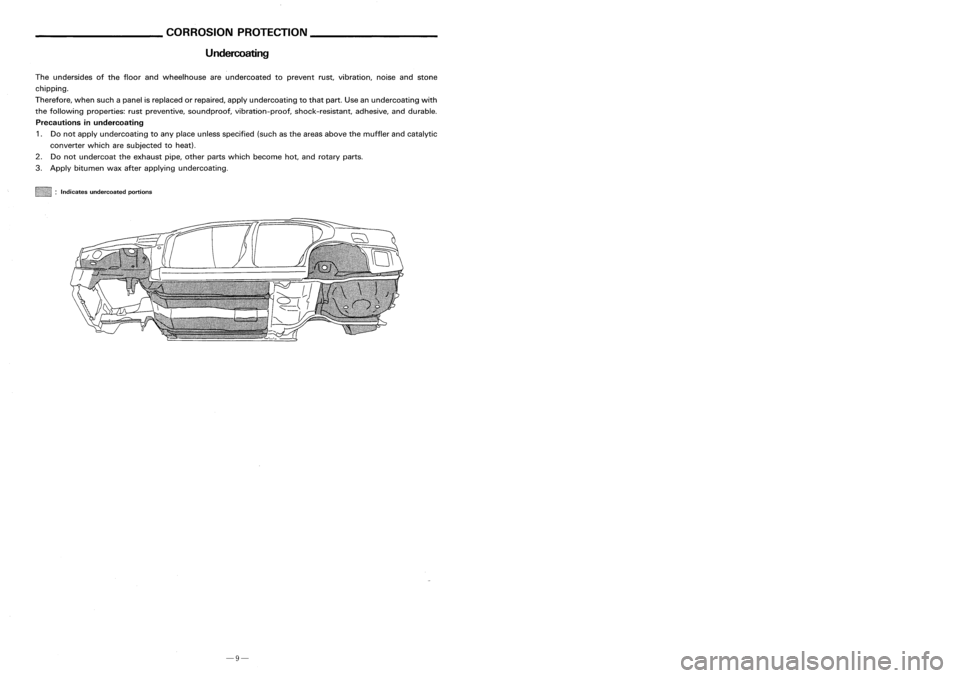
Indicates undercoated portions
The
undersides ofthe floor andwheelhouse areundercoated toprevent rust,vibration, noiseandstone
chipping.
Therefore, whensuchapanel isreplaced orrepaired, applyundercoating tothat part. Useanundercoating with
the following properties: rustpreventive, soundproof, vibration-proof, shock-resistant, adhesive,anddurable.
Precautions inundercoating
1. Donot apply undercoating toany place unless specified (suchasthe areas above themuffler andcatalytic
converter whicharesubjected toheat).
2. Donot undercoat theexhaust pipe,other partswhich become hot,androtary parts.
3. Apply bitumen waxafter applying undercoating.
2-spotwelds 3-spotwelds
M.I.G plug wel(d For3panels plugweld method )..~:
G(F:~dm
weld/
• rr= •
A
==-=.
B~
.LLLL
GTJ --- ~
-9-
-36-
Page 194 of 1701
__________ BODYALIGNMENT _
_HANDLINGPRECAUTIONS FORPLASTICS _
Passenger Compartment Sedan
5-door Hatchback Location
OfPlastic Parts
Side turnsignal lamplens
(Lens: AS)
Housing: ASS
Wind-shield molding
(Upper: PVC )
Side:Stainless+PVC
Doorout-side molding
(Stainless+PVC)
Wheel cover
(Full cover: PP+PA6 )
Half cover: PA66+PPO
Center cap:PA6
Door
mirror
(Housing: AAS)
Garnish: ASS
Front turnsignal lamp
(Lens: PMMA)
Housing: PP
Fog
lamp
(Lens: Glass)
Housing: PP
Head
lamp
(Lens: Glass)
Housing: pp
Radiator grille
(ABS)
Fog lamp finisher
(PM MA)
Front
bumper fascia
(PP)
Front airspoiler
(PP)
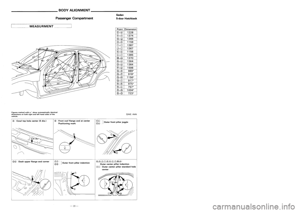
Point
Dimension
@-@
1228
CB-
@-@
1366
(8)-{6)
1159
CD--cD
1387
Q)-{J) 1367
@--@
1156
(b)--{[)
1385
~-4iV
1370
@~
1364
@~
1364
C'e)--@
1598
@--@
989*
@-{E)
918*
@~
1156*
@--{[)
917*
@~@
975*
@~(b)
757*
@~
1004*
@--@
723*
,
... ._MEASURMENT _
Figures marked witha
*
show symmetrically identical
dimensions onboth right andlefthand sides ofthe
vehicle.
Unit:
mm
@ :
Cowl tophole center (5dia.)
CB>
:
Front roofflange endatcenter
Positioning mark ~~
~}Outer frontpillarjoggle
Sideguard molding (PVC)
Rear combination lamp
(Lens: PMMA)
Housing: PP
Door
outside handle
(Handle: POM )
Escutcheon: POM
Mud guard (TPR)
Rear
Windowmolding
(PVC)
-for Sedan
Rear bumper fascia
(PP)
License
lamp
(Lens: PC)
Housing: PP
Trunk
lidfinisher(pp)
-for Sedan
Rear
spoiler(PPO)
-for Sedan
High mounted stoplamp
(In Rear SpoilerType)
(Lens: PMMA)-for Sedan
Housing: ASS
(Fixed Trunk LidTipe)
(Lens: PC)-for Sedan
Housing: PP
(f3),Cfi),Q),CD,@,@,CD,CD,~,@ :
Outer center pillarindention
CDCD :
Outer center pillarstandard hole
center
CBCD:
}
~@:
Outerfrontpillar indention
@@
:
Dash upper flange endcorner
-19- -26-