Page 271 of 1701

BRAKESYSTEM
SECTION
CONTENTS BR
PRECAUTIONS ANDPREPARATION
3
Precautions 3
Special Service Tools 4
Commercial ServiceTools 4
CHECK ANDADJUSTMENT 5
Checking BrakeFluidLevel 5
Checking BrakeLine 5
Changing BrakeFluid 5
AIR
BLEEDING 6
Bleeding Procedure 6
BRAKE HYDRAULIC LINE 7
Removal 8
Inspection 8
Installation 8
CONTROL VALVE 9
Proportioning Valve 9
BRAKE PEDALANDBRACKET 11
Removal andInstallation 11
Inspection 11
Adjustment 11
MASTER CYLINDER 12
Removal 12
Disassembly 12
Inspection 13
Assembly 13
Installation 14
BRAKE BOOSTER 15
On-vehicle Service 15
Removal 15
Inspection 16
Installation 16
VACUUM HOSE 17
Removal andInstallation 17
Inspection 17
FRONT DISCBRAKE 19
Pad Replacement.. 19
Removal 22
Disassembly 22Inspection
-Caliper 22
Inspection -Rotor 23
Assembly '".23
Installation 24
REAR DRUM BRAKE 25
Removal 25
Inspection -Wheel Cylinder 26
Wheel Cylinder Overhaul 27
Inspection -Drum 27
Inspection -Lining 27
Installation 27
REAR DISCBRAKE 29
Pad Replacement 29
~~s:~::~'~I~':::::::::::'::: ::.::::::::.::::::.::::::::::.::::::.::::::::~~ •••
Inspection -Caliper 32
Inspection -Rotor 33
Assembly 33
Installation 35
PARKING BRAKECONTROL 36
Removal andInstallation 36
Inspection 36
Adjustment ." 37
ANTI-LOCK BRAKESYSTEM 38
Purpose 38
Operation 38
ABS Hydraulic Circuit 38
System Components 39
System Description 39
Removal andInstallation .40
Wiring Diagram -ABS - .45
TROUBLE DIAGNOSES
52
Contents 52
Component PartsandHarness Connector
Location 64
SERVICE DATAANDSPECIFICATIONS (SDS)86
General Specifications 86
Inspection andAdjustment 88
Page 273 of 1701

PRECAUTIONSANDPREPARATION
Precautions
SUPPLEMENTAL RESTRAINTSYSTEM(SRS)"AIRBAG"
(DUAL AIRBAG SYSTEM)
The Supplemental RestraintSystem"AirBag" usedalong with
a seat belt,helps toreduce therisk orseverity ofinjury tothe
driver andfront passenger inafrontal collision. TheSupple-
mental Restraint Systemconsists ofair bag modules (located
in the center ofthe steering wheelandonthe instrument panel
on the passenger side),adiagnosis sensorunit,warning lamp,
wiring harness andspiral cable. Information necessarytoser-
vice thesystem safelyisincluded inthe
RSsection
ofthis Ser-
vice Manual.
WARNING:
• Toavoid rendering theSRS inoperatiYe, whichcouldincrease therisk ofpersonal injuryordeath
in the event ofacollision whichwould resultinair bag inflation, allmaintenance mustbeperformed
by an authorized NISSANdealer.
• Improper maintenance, includingincorrectremovalandinstallation ofthe SRS, canlead topersonal
injury caused byunintentional activationofthe system.
• Donot use electrical testequipment onany circuit related tothe SRS unless instructed tointhis
Service Manual. SRSwiring harnesses arecovered withyellow insulation eitherjustbefore the
harness connectors orfor the complete harness,foreasy identification.
SUPPLEMENTAL RESTRAINTSYSTEM(SRS)"AIRBAG"
(SINGLE AIRBAG SYSTEM)
The Supplemental RestraintSystem"AirBag" andused along withaseat belt,helps toreduce therisk
or severity ofinjury tothe driver inafrontal collision. TheSupplemental RestraintSystemconsists of
an air bag module (located inthe center ofthe steering wheel),adiagnosis sensorunit,warning lamp,
wiring harness andspiral cable. Information necessarytoservice thesystem safelyisincluded inthe
RS section
ofthis Service Manual.
WARNING:
• Toavoid rendering theSRS inoperative, whichcouldincrease therisk ofpersonal injuryordeath
in the event ofacollision whichwould resultinair bag inflation, allmaintenance mustbeperformed
by an authorized NISSANdealer.
• Improper maintenance, includingincorrectremovalandinstallation ofthe SRS, canlead topersonal
injury caused byunintentional activationofthe system.
• Donot use electrical testequipment onany circuit related tothe SRS unless instructed tointhis
Service Manual.
BR-3
•
Page 274 of 1701

GG94310000or
commercial equivalent
SBR820BA
For
tightening flarenut
Tool number
Tool name
PRECAUTIONS
ANDPREPARATION
Precautions (Conl'd)
BRAKE SYSTEM
• Recommended fluidisbrake fluid"DOT 3"or"DOT 4".
• Never reusedrained brakefluid.
• Donot mix different typesofbrake fluids (DOT3,DOT 4).
• Becareful nottosplash brakefluidonpainted areas;itmay
cause paintdamage. Ifbrake fluidissplashed onpainted
areas, washitaway withwater immediately.
• Toclean master cylinder parts,discbrake caliper partsor
wheel cylinder parts,useclean brake fluid.
• Never usemineral oilssuch asgasoline orkerosene. They
will ruin rubber partsofhydraulic system.
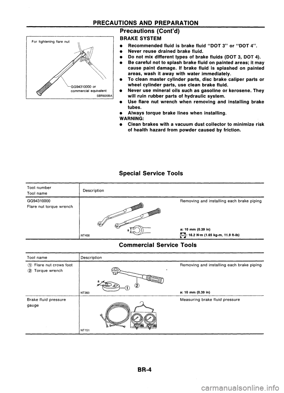
• Use flare nutwrench whenremoving andinstalling brake
tubes.
• Always torquebrakelineswhen installing.
WARNING:
• Clean brakes withavacuum dustcollector tominimize risk
of health hazard frompowder causedbyfriction.
Special Service Tools
Description
GG9431 0000
Flare nuttorque wrench
NT406
Removing
andinstalling eachbrake piping
a: 10 mm (0.39 in)
~: 16.2N'm(1.65 kg-m, 11.9f1-lb)
Commercial ServiceTools
Description
Tool name
CD
Flare nutcrows foot
@ Torque wrench
Brake fluidpressure
gauge
NT360
NT151
Removing
andinstalling eachbrake piping
a: 10 mm (0.39 in)
Measuring brakefluidpressure
BR-4
Page 281 of 1701
SEC.465
iii :
N'm (kg-m, in-Ib)
~ :N'm (kg-m, ft-Ib)
BRAKE
PEDALANDBRACKET
Removal andInstallation
Sloplamp sWitch
SBR205D
o
Inspection
Check brakepedalforfollowing items:
• Brake pedalbend
• Clevis pindeformation
• Crack ofany welded portion
• Crack ordeformation ofclevis pinstopper
•
SBR997
Adjustment
Check brakepedalfreeheight fromdash reinforcement panel
(RHD) anddash lower panel (LHD). Adjust ifnecessary.
H: Freeheight
Refer to
50S
(BR-SS).
0: Depressed height
Refer to
50S
(BR-SS).
Under forceof
490
N
(50
kg,
110
Ib)
with engine running
1. Loosen locknutand adjust pedalfreeheight byturning
brake booster inputrod.Then tighten locknut.
2. Check pedalfreeplay.
Make surethatstop lamps gooff when pedal isreleased.
3. Check brakepedal's depressed heightwhileengine isrun-
ning. If lower thanspecification, checkforleaks, airinsystem or
damage tocomponents (mastercylinder, wheelcylinder,
etc.). Then make necessary repairs.
SBR034D BR-11
Page 293 of 1701

Pistonbootretainer (AD22VF only)
Piston boot
Piston seal
FRONT
DISCBRAKE
Inspection -Caliper (Cont'd)
PISTON
Check pistonforscore, rust,wear, damage orpresence offor-
eign objects. Replace ifany ofthe above conditions are
observed.
CAUTION:
Piston sliding surface isplated. Donot polish withemery paper
even ifrust orforeign objects arestuck tosliding surface.
SLIDE PIN,PINBOLT ANDPINBOOT
Check forwear, cracks, rustorother damage. Replaceifany of
the above conditions areobserved.
Inspection -Rotor
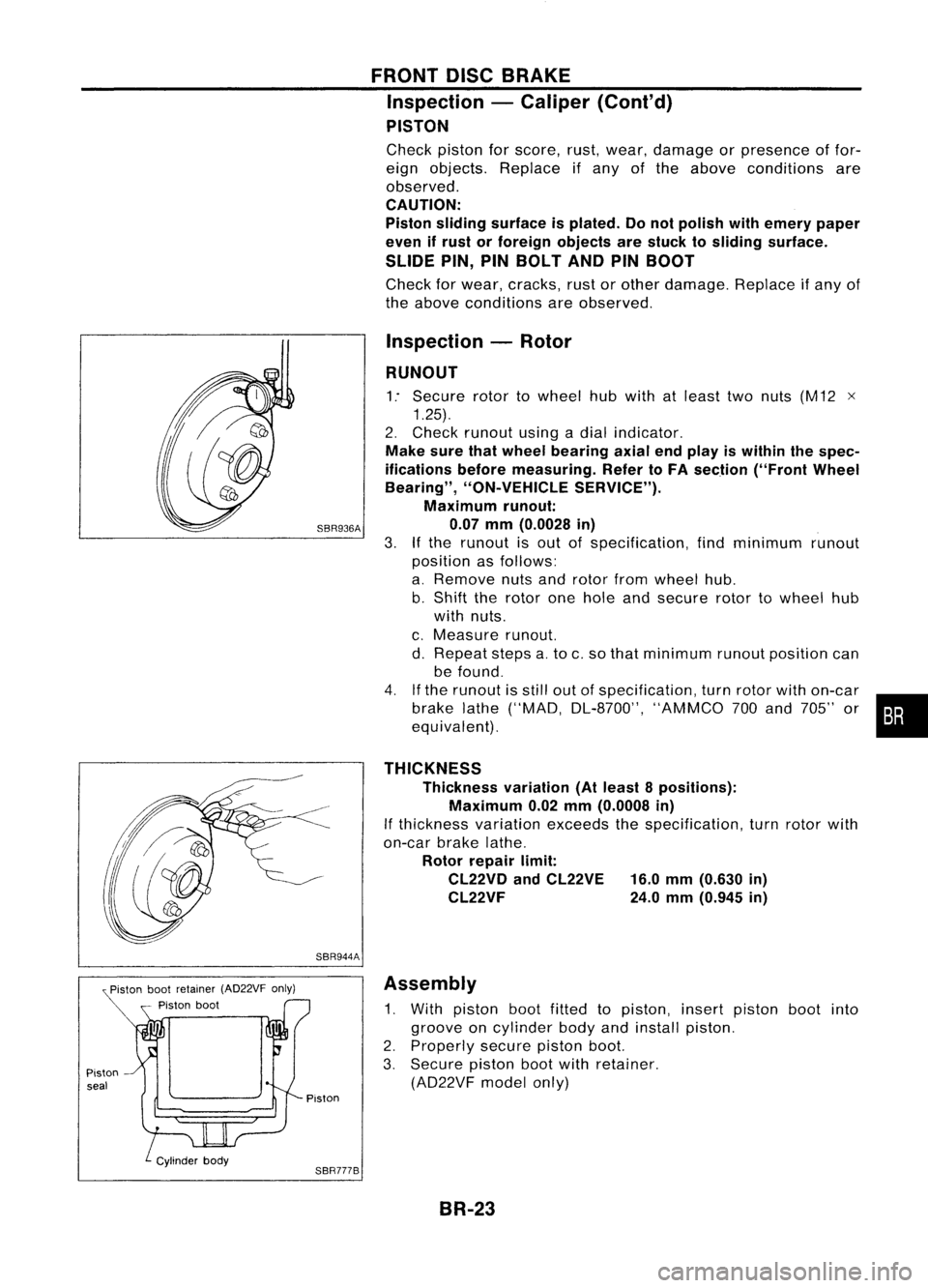
RUNOUT
1: Secure rotortowheel hubwith atleast twonuts (M12 x
1.25).
2. Check runout usingadial indicator.
Make surethatwheel bearing axialendplay iswithin thespec-
ifications beforemeasuring. RefertoFA section ("FrontWheel
Bearing", "ON-VEHICLE SERVICE").
Maximum runout:
SBR936A 0.07mm(0.0028 in)
3.
If
the runout isout ofspecification, findminimum runout
position asfollows:
a. Remove nutsandrotor fromwheel hub.
b. Shift therotor onehole andsecure rotortowheel hub
with nuts.
c. Measure runout.
d. Repeat stepsa.to c.so that minimum runoutposition can
be found.
4. Ifthe runout isstill outofspecification, turnrotor withon-car
brake lathe("MAD, DL-8700", "AMMCO700and 705" or•••
equivalent).
THICKNESS Thickness variation(Atleast 8positions):
Maximum 0.02mm(0.0008 in)
If thickness variationexceedsthespecification, turnrotor with
on-car brakelathe.
Rotor repair limit:
CL22VD andCL22VE 16.0mm(0.630 in)
CL22VF 24.0mm(0.945 in)
SBR944A Assembly
1. With piston bootfitted topiston, insertpiston bootinto
groove oncylinder bodyandinstall piston.
2. Properly securepistonboot.
3. Secure pistonbootwithretainer.
(AD22VF modelonly)
Piston
SBR777B BR-23
Page 295 of 1701
SEC.441
REAR
DRUM BRAKE
Front
m,W.
Rubber greasePOint
• .Brake grease point
~ :N.m (kg-m, f1-lb)
/il.
N.m(kg-m, in-Ib)
SBR772BC
Cl)
Wheel
cylinder assembly
(J)
Return spring
@
Shoe hold-down spring
@
Boot
@
Adjuster
@
Toggle lever
@
Piston
@
Shoe
@
Washer
@
Piston cup
@)
Adjuster lever
@
Retainer ring
@
Cylinder body
@
Adjuster spring
@
Shoe hold-down pin
@
Spring
@
Retainer
@
Plug
Removal
WARNING:
Clean brakeliningwithavacuum dustcollector tominimize the
hazard ofairborne particles orother materials.
CAUTION: Make sureparking brakeleverisreleased completely.
BR-25
•
Page 296 of 1701
Bolts
(M8
x
1.25) Wheel
cylinder
Adjuster
SBR280B
SBR020A REAR
DRUM BRAKE
Removal (Cont'd)
1. Release parkingbrakeleverfully,thenremove drum.
If drum ishard toremove, thefollowing procedures shouldbe
carried out.
a. Remove plug.Thenshorten adjuster tomake clearance
between brakeshoeanddrum asshown.
b. Tighten thetwo bolts gradually.
SBR785BA
2.
After removing retainer,removespringbyrotating shoes.
• Becareful nottodamage wheelcylinder pistonboots.
• Becareful nottodamage parkingbrakecablewhensepa-
rating it.
3. Remove adjuster.
4. Disconnect parkingbrakecablefromtoggle lever.
5. Remove retainerringwith asuitable tool.Then separate
toggle leverandbrake shoe.
Inspection -Wheel Cylinder
• Check wheelcylinder forleakage.
• Check forwear, damage andloose conditions.
Replace ifany such condition exists.
BR-26
Page 297 of 1701
SBR215BREAR
DRUM BRAKE
Wheel Cylinder Overhaul
• Check allinternal partsforwear, rustanddamage. Replace
if necessary.
• Pay attention soasnot toscratch cylinder wheninstalling
pistons.
SBR022A Inspection
-Drum
Maximum innerdiameter:
181 mm (7.13 in)
Out-of-roundness: 0.03 mm(0.0012 in)orless
• Contact surfaceshouldbefine finished withNo.120to150
emery paper.
• Using adrum lathe, lathebrake drumifitshows scoring,
partial wearorstepped wear.
• After brake drumhasbeen completely reconditioned or
replaced, checkdrumandshoes forproper contact pattern.
•
A
SBR021AInspection
-Lining
Check liningthickness.
Standard liningthickness:
4.0 mm (0.157 in)
Lining wearlimit(A):
1.5 mm (0.059 in)
Installation
Always perform shoeclearance adjustment. Referto
"Adjustment" in"PARKING BRAKECONTROL", BR.37.
1. Fittoggle levertobrake shoewithretainer ring.
BR-27