Page 298 of 1701
SBR216B
~ ~Vohi'" 'COol
DepreSSi~~
"
~
/
SBR217B
SBR279B
REAR
DRUM BRAKE
Installation (Cont'd)
2. Apply brake grease tothe contact areasshown atleft.
3. Shorten adjuster byrotating it.
• Pay attention todirection ofadjuster.
Wheel Screw Depression
Left Left-handthread
Yes
Right Right-handthread No
4. Connect parkingbrakecabletotoggle
lever.
5. Install allparts.
Be careful nottodamage wheelcylinder pistonboots.
6. Check allparts areinstalled properly.
Pay attention todirection ofadjuster assembly.
7. Install brakedrum.
8. When installing newwheel cylinder oroverhauling wheel
cylinder, bleedair.Refer to"Bleeding procedure", BR-6.
9. Adjust parking brake.RefertoBR-37.
BR-28
Page 303 of 1701
SBR847
SBR247B REAR
DISCBRAKE
Inspection -Rotor
RUBBING SURFACE
Check rotorforroughness, cracksorchips.
RUNOUT
1. Secure rotortowheel hubwith atleast twonuts (M12 x1.25).
2. Check runout usingadial indicator.
Make surethatwheel bearing axialendplay iswithin thespec-
ifications beforemeasuring. Referto"Rear Wheel Bearing" of
"ON-VEHICLE SERVICE"inRA section.
3. Change relativepositions ofrotor andwheel hubsothat
runout isminimized.
Maximum runout:
0.07 mm(0.0028 in)
THICKNESS Rotor repair limit:
Minimum thickness
CL7HB 6.0mm (0.236 in)
CL9HC 8.0mm (0.315 in)
Thickness variation(Atleast 8portions)
Maximum 0.02mm(0.0008 in)
Replace rotorifany ofthe above donot meet thespecifications .
Assembly
1. Insert camwithdepression facingtowards openendofcyl-
inder.
2. Generously applyrubber grease tostrut andpush rodto
make insertion easy.
BR-33
•
Page 308 of 1701

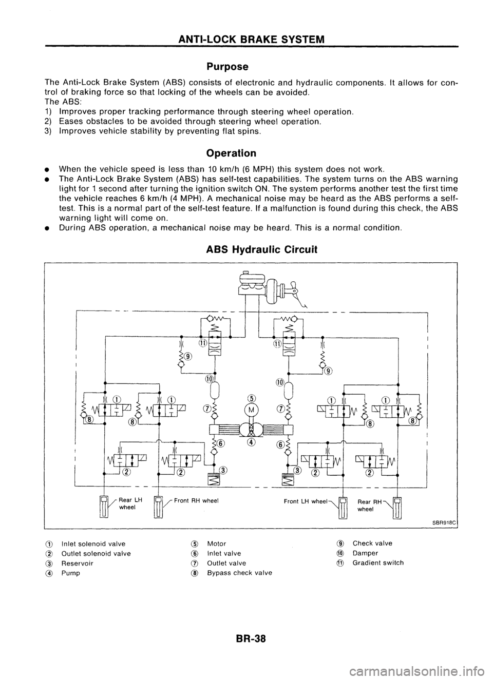
ANTI-LOCKBRAKESYSTEM
Purpose
The Anti-Lock BrakeSystem (ABS)consists ofelectronic andhydraulic components. Itallows forcon-
trol ofbraking forcesothat locking ofthe wheels canbeavoided.
The ABS:
1) Improves propertracking performance throughsteering wheeloperation.
2) Eases obstacles tobe avoided throughsteering wheeloperation.
3) Improves vehiclestability bypreventing flatspins.
Operation
• When thevehicle speedisless than 10km/h (6MPH) thissystem doesnotwork.
• The Anti-Lock BrakeSystem (ABS)hasself-test capabilities. Thesystem turnsonthe ABS warning
light for1second afterturning theignition switchON.The system performs anothertestthefirst time
the vehicle reaches 6km/h (4MPH). Amechanical noisemaybeheard asthe ABS performs aself-
test. This isanormal partofthe self-test feature.Ifa malfunction isfound during thischeck, theABS
warning lightwillcome on.
• During ABSoperation, amechanical noisemaybeheard. Thisisanormal condition.
ABS Hydraulic Circuit
G)
Inletsolenoid valve
@
Outlet solenoid valve
@
Reservoir
@)
Pump
)(
@
@
Motor
@
Inletvalve
(J)
Outlet valve
@ Bypass checkvalve
BR-38 @
Check valve
@)
Damper
@
Gradient switch
SBR918C
Page 309 of 1701

ANTI-LOCKBRAKESYSTEM
System Components
Dual proportioning
valve
Rearwheel sensors
For LHD models, controlunit
is located onthe opposite side.
SBR048DB
Control unit
s::';o~'~W.
r
Magnetic flux~ _~-Coil
I .I
Tooth~ Sensorrotor
/ ~m~f onetooth
v:~-- System
Description
SENSOR
The sensor unitconsists ofagear-shaped sensorrotoranda
sensor element. Theelement contains abar magnet around
which acoil iswound. Thesensor isinstalled onthe back side
of the brake rotor.Sine-wave currentisgenerated bythe sen-
sor asthe wheel rotates. Thefrequency andvoltage increase(s) •
as the rotating speedincreases. :•
V: Induced electromotive force
SBR124B
SBR049DA CONTROL
UNIT
The control unitcomputes thewheel rotating speedbythe sig-
nal current sentfrom thesensor. Thenitsupplies aDC current
to the actuator solenoid valve.Italso controls ON-OFFopera-
tion ofthe valve relayandmotor relay.Ifany electrical malfunc-
tion should bedetected inthe system, thecontrol unitcauses
the warning lamptolight up.Inthis condition, theASS willbe
deactivated bythe control unit,andthevehicle's brakesystem
reverts tonormal operation.
BR-39
Page 310 of 1701
ANTI-LOCKBRAKESYSTEM
Removal andInstallation
CAUTION: Be careful nottodamage sensoredgeandsensor rotorteeth.
When removing thefront orrear wheel hubassembly, discon-
nect theABS wheel sensor fromtheassembly andmove it
away.
FRONT WHEEL SENSOR
Front wheel sensor (LH) ~!Ii
3.9-5.9 (0.4 -0.6, 35-52)
~: Nom (kg-m, ft-lb)
~: Nom(kg-m, in-Ib)
SBR030DA
REAR WHEEL SENSOR
BR-40
\
L
Rear wheel sensor (LH)
~: Nom (kg-m, ft-Ib)
~: Nom(kg-m, in-Ib)
SBR031DA
Page 311 of 1701
ANTI-LOCKBRAKESYSTEM
Removal andInstallation (Cont'd)
SENSOR ROTOR
Removal
1. Remove thedrive shaftandrear wheel hub.Refer toFA
section ("DriveShaft",FRONTAXLE") andRAsection
("Wheel Hub",REARAXLE").
2. Remove thesensor rotorusing suitable puller,driftand
bearing replacer.
Suitable drift
SBR873CA
Installation
Install thesensor rotor.Forfront sensor rotor,usehammer and
wooden block.Forrear sensor rotor,usesuitable driftand
press.
• Always replace sensorrotorwithnewone.
SBR985C
•
• Pay attention tothe dimension ofrear sensor rotorasshown
in figure.
h: 4.5 -5.5 mm (0.177 -0.217 in)
CONTROL UNIT
Location: Passenger side,behind dashsidelower finisher.
• Make surethatthesensor shieldground cableissecured
with mounting bolt.
SBR986C
Suitable
drift
B,.,k" ~ ABS
.'0"'" ","
Dash side ~
lower finisher ~3.9_5.9 N.m
(0.4 -0.6 kg-m,
35 -52 In-Ib)
SBR032DA
Rear
sensor rotor
BR-41
Page 312 of 1701
,ryside
linder prima
From master cy ndaryside
r
der seco
master cyIn
From
RHO
cc:J
11-15 .11)
(1.1 .
1.5, 8
~ Front
LHO
ASS
relay
box
ground
Actuator
cable
---------~~~~~:A~K~EirS;V~S~T~EWo.M;(c:O;;~'diij)I----
ANTI-LOCK
BRdInstallation (Cont
Removal an
ABS ACTUATOR
heelcylinder (RH)
To rear
W
clinder (LH)
f ntwheel y
To ro
aster cylinder
From m
primary side
aster cylinder
From m 'de
secondary
Sl
(LH)
Wheel cylinder
To rear
W
heel cylinder (RH)
To
rear
(kg-m.in-Ib)
r.ii1
'N.m
IX! '
(kg-m. ft-Ib)
cc:J:
N.m
SBR033DA
BR-42
Page 317 of 1701
ANTI-LOCKBRAKESYSTEM
Wiring Diagram -ABS -(Cont'd)
BR-ABS-03
•
ABS
CONTROL
UNIT
LHO models
RHO models
(jJ:
(8):
GN02
GNO1 GNO
12.81 12.911
3•
9
1
B BB
Ll-l
I
----
)
I
1
I
1
----
']
W@1IDB .
$---$-]1
W
@)
8
-----
(,
-
_.
1 -- I
I I
I I
l.... •
l~t~~8}j~f
-]1
W «(1Q"n B
-----
r-- _
I I
I 1
1 1
l....
'J
R
R
~
..
1
1
I
I
I ....
l
SENSOR
FR-RH
H
~
B
t
I
o
,. 1
1
1
I
I
I
I
1
I
I
1
I
J 1
1
I
1
1
I
I
1
1
1
1
1
I
1
I ....
t
-
rn
JOINT
CONNECTOR
-7
(B109)
1
WB
~ WHEELSPEED
SENSOR
rv
FRONTRH
(1llQj)
W
B
M
WHEELSPEED
SENSOR
rv
FRONTRH
(E 11)
&~(BIT5)
5 6TII9ID 1112W ..In
em),
@ill)
<..!J.g)
GYGY
~(Eli[9)
IIlIITl.IIillJ
GY
Refer
tolast page
(Foldout page).
HBR004
BR-47