Page 1677 of 1701
STEERINGWHEELANDSTEERING COLUMN
Removal andInstallation (Cont'd)
Two spoke type
Clamp
Crosshead screwdriver~
II
SST503C
2.Remove steering wheelwithTool.
SST122B
Cr~I~I;~
~#f
~.'".
Lowerjoint
SST112B
SST800A
•
When installing steeringwheel,lubricate withmulti-purpose
grease. Applygrease toentire surface ofturn signal cancel
pins andhorn contact sliprings.
STEERING COLUMN
• When installing steeringcolumn,fingertighten alllower
bracket andclamp retaining bolts;thentighten them
securely. Donot apply undue stress tosteering column.
• When attaching couplingjoint,besure tightening boltfaces
cutout portion.
• Align slitoflower jointwithprojection ondust cover. Insert
joint untilsurface Acontacts surfaceB.
CAUTION:
After installation, turnsteering wheeltomake sureitmoves
smoothly. Ensurethenumber ofturns arethesame fromthe
straight forward position toleft and right locks. Besure thatthe
steering wheelisin aneutral position whendriving straight
ahead.
•
SST491C ST-11
Page 1678 of 1701
SEC.488 STEERING
WHEELANDSTEERING COLUMN
Disassembly andAssembly
~.N.m (kg-m, in-Ib)
~ .N.m (kg-m, ft-Ib)
SST539C
G)
Spiral cable
@
Combination switch
@
Lock nut
@
Tiltlever
@
Washer
@
Tiltlever stopper
!J)
Steering columnmounting
bracket
@
Adjust bolt
CID
Adjust boltstopper
@J
Push nut
@
Jacket tubeassembly
@
Boot
@
Steering columnshaft
@
Lower joint
@
Return spring
Lock nut
II
I
•
When disassembling andassembling, unlocksteering lock
with key.
• Install locknutonsteering columnshaftandtighten thenut
to specification.
~: 25-34 N.m (2.5-3.5 kg-m, 18-25 ft-Ib)
SST490C ST-12
Page 1679 of 1701
STEERINGWHEELANDSTEERING COLUMN
Disassembly andAssembly (Cont'd)
• Steering lock
a. Break self-shear typescrews withadrill orother appropri-
ate tool.
SST741A
b.Install newself-shear typescrews andthen cutoffself-
shear typescrew heads.
Self-shear screw
SST742A
L
-
--- ---_
..
_-------,
I
Center ofjoint
SST334C
1510.59) 15 (0.59)
Inspection
• When steering wheeldoesnotturn smoothly, checkthe
steering columnasfollows andreplace damaged parts.
a. Check column bearings fordamage orunevenness. Lubri-
cate with recommended multi-purposegreaseorreplace
steering columnasan assembly, ifnecessary.
b. Check jackettubefordeformation orbreakage. Replaceif
necessary.
• When thevehicle comesintoalight collision, checklength
ilL",
Column length
"L": •
533.0 -535.0 mm(20.98 -21.06 in)
If out ofthe specifications, replacesteering columnasan
assembly.
Tilt mechanism
• After installing steeringcolumn,checktiltmechanism oper-
ation.
Unit: mm(in)
8ST5828
ST-13
Page 1680 of 1701
MANUALSTEERING GEARANDLINKAGE (ModelR24N)
Removal andInstallation
SEC. 480
A :
N.m (kg-m, tt-Ib)
(!)
Hole cover
@
Lower joint
@
Manual steering gearassembly
@
Steering gearmounting clamp
tt'J
29•39
(3.0 -4.0,22 -", ~
~
@~ SST056CA
@
Rack mounting insulator
@
Cotter pin
CAUTION:
The rotation ofthe spiral cable(SRS"Airbag" component part)
is limited.
If
the steering gearmust beremoved, setthe front
wheels inthe straight-ahead direction.Donot rotate thesteer-
ing column whilethesteering gearisremoved.
• Detach tie-rodoutersockets fromknuckle armswithTool.
• Initially, tightennutontie-rod outersocket andknuckle arm
to 29 to39 N'm (3to 4kg-m, 22to29 ft-Ib).
• Tighten nutfurther toalign nutgroove withthefirst pinhole
so cotter pincan beinstalled.
CAUTION:
Tightening torquemustnotexceed 49N.m (5kg-m, 36ft-Ib).
ST-14
Page 1685 of 1701

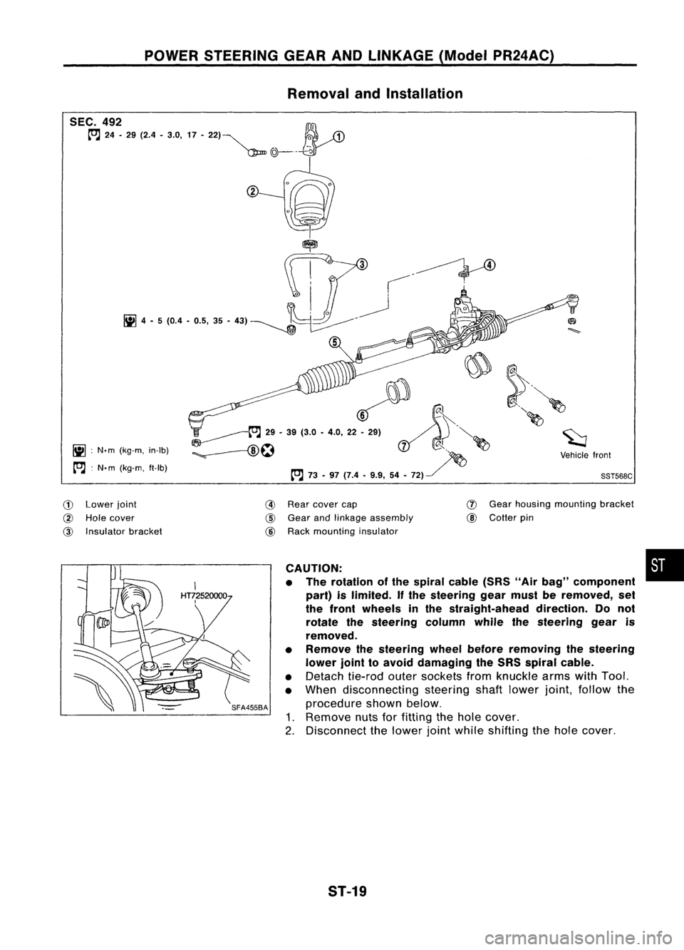
POWERSTEERING GEARANDLINKAGE (ModelPR24AC)
Removal andInstallation
~ :N.m (kg-m, in-Ib)
[O.J :
N. m (kg-m, ft-Ib)
~~.~
';'-------t"J
29•39 (3.0 •4.0, 22~ ~.'.. ~"'-
:;. --f8\~ ~
d( ~ ~
~ ~~ ~Vehiclefront
[O.J
73-97 (7.4 •9.9, 54•72) ~
'
SST568C
CD
Lower joint
@
Hole cover
@
Insulator bracket
@
Rear cover cap
@
Gear andlinkage assembly
@
Rack mounting insulator
(J)
Gear housing mounting bracket
@
Cotter pin
CAUTION: •
• The rotation ofthe spiral cable(SRS"Airbag" component
part) islimited.
If
the steering gearmust beremoved, set
the front wheels inthe straight-ahead direction.Donot
rotate thesteering columnwhilethesteering gearis
removed.
• Remove thesteering wheelbefore removing thesteering
lower jointtoavoid damaging theSRS spiral cable.
• Detach tie-rodoutersockets fromknuckle armswithTool.
• When disconnecting steeringshaftlower joint,follow the
procedure shownbelow.
1. Remove nutsforfitting thehole cover.
2. Disconnect thelower jointwhile shifting thehole cover.
ST-19
Page 1686 of 1701

POWERSTEERING GEARANDLINKAGE (ModelPR24AC)
Removal andInstallation (Cont'd)
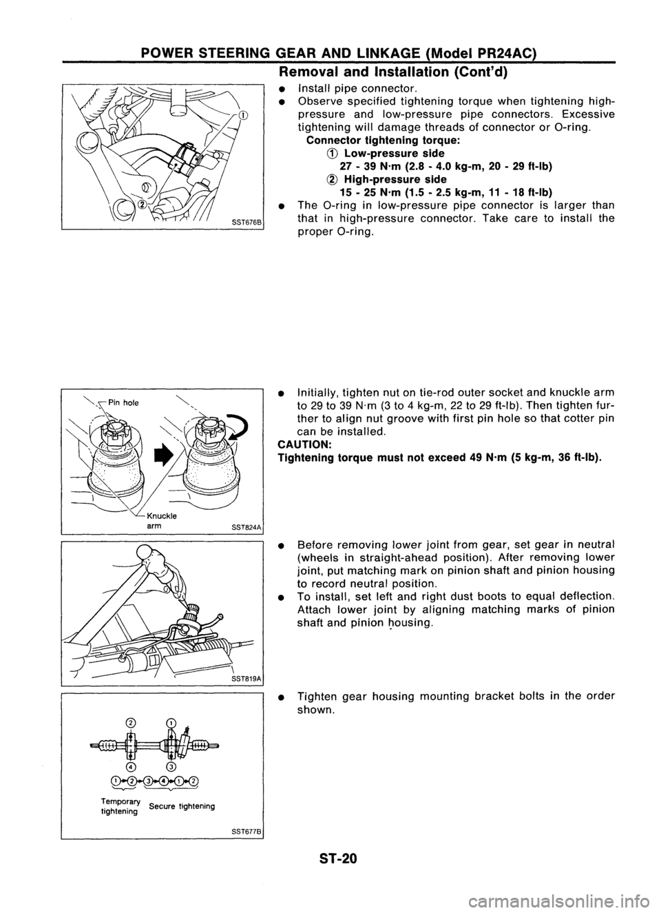
• Install pipeconnector.
• Observe specified tightening torquewhentightening high-
pressure andlow-pressure pipeconnectors. Excessive
tightening willdamage threadsofconnector orO-ring.
Connector tighteningtorque:
CD
Low-pressure side
27 -39 N'm (2.8-4.0 kg-m, 20-29 ft-Ib)
~ High-pressure side
15 -25 N'm (1.5-2.5 kg-m, 11-18 ft-Ib)
• The O-ring inlow-pressure pipeconnector islarger than
that inhigh-pressure connector.Takecaretoinstall the
proper O-ring.
• Initially, tightennutontie-rod outersocket andknuckle arm
to 29 to39 N'm (3to 4kg-m, 22to29 ft-Ib). Thentighten fur-
ther toalign nutgroove withfirstpinhole sothat cotter pin
can beinstalled.
CAUTION:
Tightening torquemustnotexceed 49N'm (5kg-m, 36ft-Ib).
• Before removing lowerjointfrom gear, setgear inneutral
(wheels instraight-ahead position).Afterremoving lower
joint, putmatching markonpinion shaftandpinion housing
to record neutral position.
• Toinstall, setleftand right dustboots toequal deflection.
Attach lowerjointbyaligning matching marksofpinion
shaft andpinion ~ousing.
• Tighten gearhousing mounting bracketboltsinthe order
shown.
o
@
~
'--v---' ~
Temporary ..
tightening SecuretIghtening
SST6778
ST-20
Page 1700 of 1701
SERVICEDATAANDSPECIFICATIONS (SOS)
General Specifications
CD and SR
Applied model GAengine model engine
models
Steering model Manual
Powersteering
steering
Steering geartype R24N PR24AC
Steering overallgear
23.2 17.1
ratio
Turns ofsteering wheel
4.21 3.172.95
(Lock tolock)
Steering columntype Collapsible,tilt
Inspection andAdjustment
GENERAL
Steering wheelaxialplay
mm (in)
Steering wheelplay mm(in)
Movement ofgear housing
mm (in)
STEERING COLUMN
Applied model
Steering columnlength"L"
mm (in)
L
'"
'- Center ofjoint 0(0)
35 (1.38) orless
:!:
2 (
:!:
0.08) orless
All
533.0 -535.0
(20.98 -21.06)
SST334C
ST-34
Page 1701 of 1701

SERVICEDATAANDSPECIFICATIONS (50S)
Inspection andAdjustment (Cont'd)
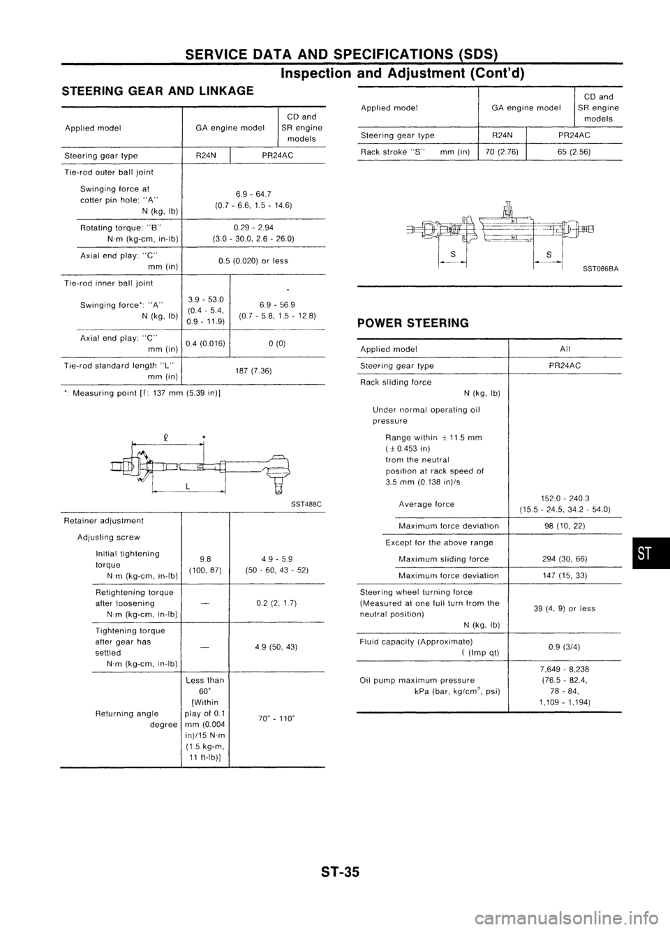
STEERING GEARANDLINKAGE
CDand
Applied model GA
engine model SRengine
models
Steering geartype R24NPR24AC
Tie-rod outerballjoint
Swinging forceat
6.9-64.7
cotter pinhole: "A"
(0.7-6.6, 1.5-14.6)
N (kg, Ib)
Rotating torque:"B" 0.29
-294
N'm (kg-em, in-Ib) (30
-30.0, 26-260)
Axial endplay: "C"
0.5(0.020) orless
mm (in)
Tie-rod innerballjoint
.
Swinging force":"A" 3.9
-53.0
6.9-569
(0.4 -5.4,
N (kg, Ib)
0.9-11.9) (07
-58,1.5 -12.8)
Axial endplay: "C"
0.4(0.016)
a
(0)
mm (in)
Tie-rod standard length"L"
187(7.36)
mm (in)
". Measuring point
[f:
137 mm (5.39 in)]
SST488C
Retainer adjustment
Adjusting screw
Initial tightening
984.9
-5.9
torque (100,87)(50-60, 43-52)
Nm (kg-em, in-Ib)
Retightening torque
after loosening
-
02
(2,1.7)
N'm (kg-em, in-Ib)
Tightening torque
after gear has
-
49(50, 43)
settled
N'm (kg-em, in-Ib)
Lessthan
60'
[Within
Returning angle play
of0.1
70'-110'
degree mm
(0.004
in)/15 N'm
(1.5 kg-m,
11 ft-Ib)] CD
and
Applied model GAengine model SRengine
models
Steering geartype R24N
PR24AC
Rack stroke "S" mm(in) 70(2.76) 65(2.56)
POWER STEERING
Applied model All
Steering geartype PR24AC
Rack sliding force
N(kg, Ib)
Under normal operating oil
pressure
Range within ~.115 mm
(:1:0.453 in)
from theneutral
position atrack speed of
3.5 mm (0.138 in)/s
Average force 1520
-2403
(15.5 -24.5, 34.2-54.0)
Maximum forcedeviation 98(10, 22)
Except forthe above range
Maximum slidingforce 294(30, 66)
Maximum forcedeviation 147
(15, 33)
Steering wheelturning force
(Measured atone fullturn from the
39(4, 9)or less
neutral position)
N(kg, Ib)
Fluid capacity (Approximate)
0.9(3/4)
f
(Imp qt)
7,649-8,238
Oil pump maximum pressure (76.5
-82.4,
kPa (bar, kg/em?, psi) 78-84,
1,109 -1,194)
•
ST-35