Page 201 of 1701

__________ BODYALIGNMENT _
_HANDLINGPRECAUTIONS FORPLASTICS _
Passenger Compartment Sedan
5-door Hatchback Location
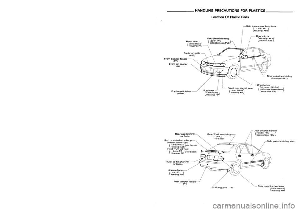
OfPlastic Parts
Side turnsignal lamplens
(Lens: AS)
Housing: ASS
Wind-shield molding
(Upper: PVC )
Side:Stainless+PVC
Doorout-side molding
(Stainless+PVC)
Wheel cover
(Full cover: PP+PA6 )
Half cover: PA66+PPO
Center cap:PA6
Door
mirror
(Housing: AAS)
Garnish: ASS
Front turnsignal lamp
(Lens: PMMA)
Housing: PP
Fog
lamp
(Lens: Glass)
Housing: PP
Head
lamp
(Lens: Glass)
Housing: pp
Radiator grille
(ABS)
Fog lamp finisher
(PM MA)
Front
bumper fascia
(PP)
Front airspoiler
(PP)
Point
Dimension
@-@
1228
CB-
1374
@-@
1366
(8)-{6)
1159
CD--cD
1387
Q)-{J) 1367
@--@
1156
(b)--{[)
1385
~-4iV
1370
@~
1364
@~
1364
C'e)--@
1598
@--@
989*
@-{E)
918*
@~
1156*
@--{[)
917*
@~@
975*
@~(b)
757*
@~
1004*
@--@
723*
,
... ._MEASURMENT _
Figures marked witha
*
show symmetrically identical
dimensions onboth right andlefthand sides ofthe
vehicle.
Unit:
mm
@ :
Cowl tophole center (5dia.)
CB>
:
Front roofflange endatcenter
Positioning mark ~~
~}Outer frontpillarjoggle
Sideguard molding (PVC)
Rear combination lamp
(Lens: PMMA)
Housing: PP
Door
outside handle
(Handle: POM )
Escutcheon: POM
Mud guard (TPR)
Rear
Windowmolding
(PVC)
-for Sedan
Rear bumper fascia
(PP)
License
lamp
(Lens: PC)
Housing: PP
Trunk
lidfinisher(pp)
-for Sedan
Rear
spoiler(PPO)
-for Sedan
High mounted stoplamp
(In Rear SpoilerType)
(Lens: PMMA)-for Sedan
Housing: ASS
(Fixed Trunk LidTipe)
(Lens: PC)-for Sedan
Housing: PP
(f3),Cfi),Q),CD,@,@,CD,CD,~,@ :
Outer center pillarindention
CDCD :
Outer center pillarstandard hole
center
CBCD:
}
~@:
Outerfrontpillar indention
@@
:
Dash upper flange endcorner
-19- -26-
Page 211 of 1701

Undercoating REPLACEMENT
OPERATIONS
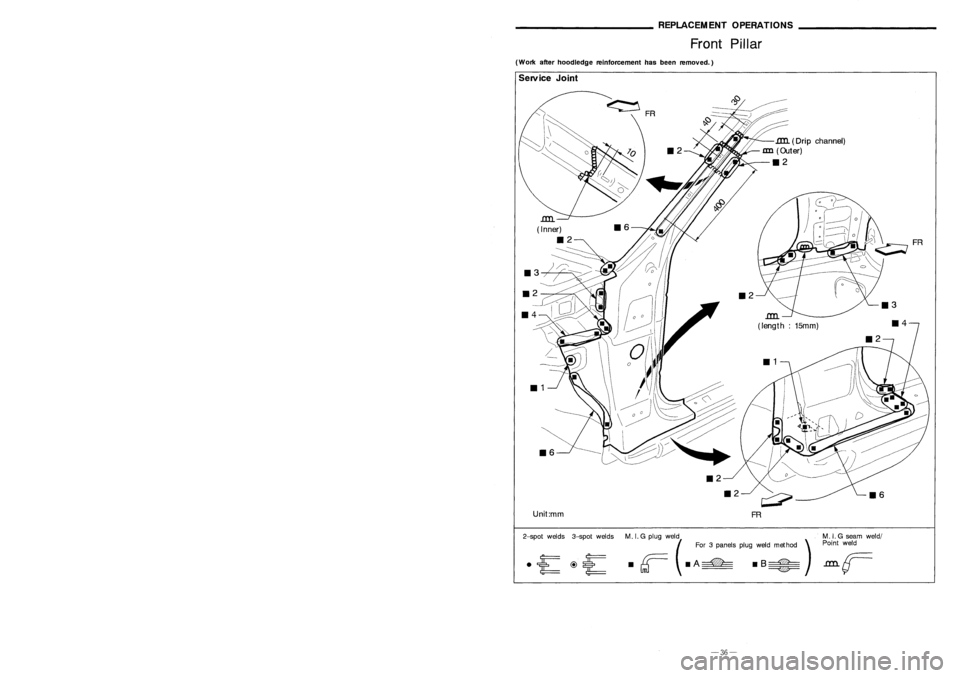
Front Pillar
(Work afterhoodledge reinforcement hasbeen removed.)
116
1lIl..
(Dri pchannel)
an
(Outer)
112
c;;;;?
FR
112
112
116
Unit:mm
<:=i
FR
1lIl..
( Inner)
112
~
113 :::::-----
Service
Joint
~I!!!!!!!!iiii!!!!!i!II :
Indicates undercoated portions
The
undersides ofthe floor andwheelhouse areundercoated toprevent rust,vibration, noiseandstone
chipping.
Therefore, whensuchapanel isreplaced orrepaired, applyundercoating tothat part. Useanundercoating with
the following properties: rustpreventive, soundproof, vibration-proof, shock-resistant, adhesive,anddurable.
Precautions inundercoating
1. Donot apply undercoating toany place unless specified (suchasthe areas above themuffler andcatalytic
converter whicharesubjected toheat).
2. Donot undercoat theexhaust pipe,other partswhich become hot,androtary parts.
3. Apply bitumen waxafter applying undercoating.
2-spotwelds 3-spotwelds
M.I.G plug wel(d For3panels plugweld method )..~:
G(F:~dm
weld/
• rr= •
A
==-=.
B~
.LLLL
GTJ --- ~
-9-
-36-
Page 218 of 1701

REPLACEMENTOPERATIONS
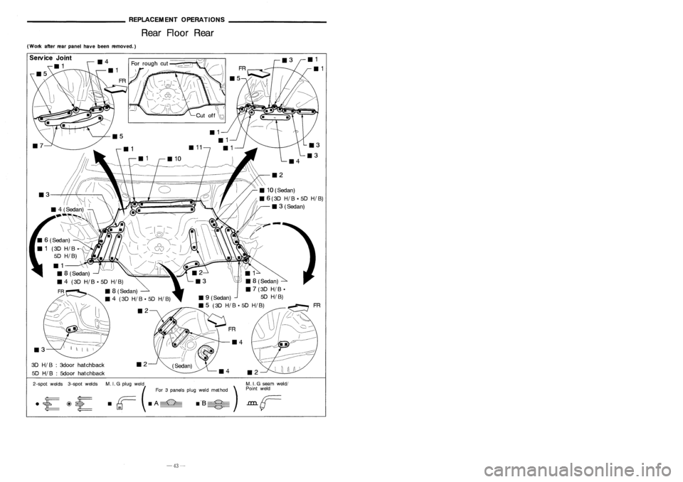
Rear Floor Rear ________
GENERALINFORMATION _
Identification Number(Cont'd)
(Work afterrearpanel havebeen removed.)
ExceptforEurope
IN 1 .B CAN 15A
0
XXXXXX
T
T
--c:::
serialnumber
0:
Stopgap (nomeaning)
Destination
A: Australia andNew Zealand
Z: Except forEurope, Australia, andNew Zealand
Model
A: 2-wheel drive
Engine type
B: GA 15DE engine
C: GA 16DE engine
E: SR20DE engine-For AustraliaandNew Zealand only
Body type
B: 4-door Sedan
F: 5-door Hatchback
Manufacturer
IN 1:Nissan, Passenger vehicle
VEHICLE IDENTIFICATION PLATE
1Type approval number
2 Vehicle identification
number(Chassis number)
3 Gross vehicle weight
4 Gross combination weight
Gross vehicle weight
+
Gross trailing capacity
(Weight)
5 Gross axleweight(Front)
6 Gross axleweight(Rear)
7 Type approval number
8 Body colorcode
9 Trim color code
10 Model Specification No.
11 Engine model
12 Engine displacement
13 Transaxle model
14 Axle model
cc
o
PLANT
PlANTA
El
ii:
13IJJ
if[
**
it~
*1
MADEINJAPAN
NISSAN
MOTORCO.,LTD. APAN
~ tt
~(:l
&
~~~sg~
CNHOA"SIS ~
~~~~~o
&
o ~
0
:ggtg~
~~~RNICION ~
&.
~~ ~~~~~ &
£
; ;~)~ /~~~~~'. AE~~
A1L11
Expect
Europe
~
&
kgO
1-
&
kg
2-
&
kg
COlOR. TRIM
~
&
FARBE. POlST
&
NISSAN
MOTORCO.,LTD. JAPAN
I ~ I
~
o
TYPE
TTP
Europe
FR
_2
3D
HI
B:3door hatchback
5D
HI
B:5door hatchback
Service
Joint
111
~
2-spot welds 3-spotwelds M.
I.
G plug weld .MIG seam weld/
(For 3panels plugweld method )P:
F
weld
• rr=- •
A
===-=
.'S~
.L.LLL
GTJ --- ~
-43-
-2-
Page 219 of 1701
~~~~~~~~_GENERALJNFORM~ION~~~~~~~~_
IdentificationNumber _
REPLACEMENTOPERATIONS
Rear SideMember Extension
Sedan
-------
/
/\
---
/ \ -
'------- /~ ,,\I
c-
~ ~>~
111
114
Service
Joint
SGI908
Vehicle
identification plate
A
A
Vehicle
identification number
N15 U
0
xxxxxx.
T
T
---c::
serialnumber
0:
Stopgap (nomeaning)
Destination
U: Europe
Model
A: 2-wheel drive
Engine type
A: GA 14DE engine
C: GA 16DE engine
E: SR20DE engine
F: CD20 engine
Body type
B: 4-door Sedan
F: 5-door Hatchback
E: 3-door Hatchback
Manufacturer
J
N 1: Nissan, Passenger vehicle
Emission
controlinformation label
VEHICLE IDENTIFICATION NUMBERARRANGEMENT
For Europe
• JN1 B
2-spotwelds 3-spotwelds M.I.G plug weld
(For 3panels plugweld method )
d
r;==
dA~ dB~
GTJ ~
M.
I.G seam weld/
Point weld
-1-
-44-
Page 222 of 1701

PRECAUTIONS
Service Notice
• When removing orinstalling variousparts,placeacloth orpadding ontothevehicle bodytoprevent
scratches.
• Handle trim,molding, instruments, grille,etc.carefully duringremoving orinstalling. Becareful not
to soil ordamage them.
• Apply sealing compound wherenecessary wheninstalling parts.
• When applying sealingcompound, becareful thatthesealing compound doesnotprotrude from
parts.
• When replacing anymetal parts(forexample bodyouter panel, members, etc.),besure totake rust
prevention measures.
SupplementalRestraintSystem(SRS)"AIR
BAG" (DualAirBag System)
The Supplemental RestraintSystem"AirBag", usedalong withaseat belt,helps toreduce therisk or
severity ofinjury tothe driver andfront passenger inafrontal collision. TheSupplemental Restraint
System consists ofair bag modules (locatedinthe center ofthe steering wheelandonthe instrument
panel onthe passenger side),adiagnosis sensorunit,warning lamp,wiring harness andspiral cable.
Information necessarytoservice thesystem safelyisincluded inthe
RSsection
ofthis Service Manual.
WARNING:
• Toavoid rendering theSRS inoperative, whichcouldincrease therisk ofpersonal injuryordeath
in the event ofacollision whichwould resultinair bag inflation, allmaintenance mustbeperformed
by an authorized NISSANdealer.
• Improper maintenance, includingincorrectremovalandinstallation ofthe SRS, canlead topersonal
injury caused byunintentional activationofthe system.
• Donot use electrical testequipment onany circuit related tothe SRS unless instructed tointhis
Service Manual. SRSwiring harnesses arecovered withyellow insulation eitherjustbefore the
harness connectors orfor the complete harness,foreasy identification.
Supplemental RestraintSystem(SRS)"AIR
BAG" (Single AirBag System)
The Supplemental RestraintSystem"AirBag", usedalong withaseat belt,helps toreduce therisk or
severity ofinjury tothe driver inafrontal collision. TheSupplemental RestraintSystemconsists ofan
air bag module (located inthe center ofthe steering wheel),adiagnosis sensorunit,warning lamp,
wiring harness andspiral cable. Information necessarytoservice thesystem safelyisincluded inthe
RS section
ofthis Service Manual.
WARNING:
• Toavoid rendering theSRS inoperative, whichcouldincrease therisk ofpersonal injuryordeath
in the event ofacollision whichwould resultinair bag inflation, allmaintenance mustbeperformed
by an authorized NISSANdealer.
• Improper maintenance, includingincorrectremovalandinstallation ofthe SRS, canlead topersonal
injury caused byunintentional activationofthe system.
• Donot use electrical testequipment onany circuit related tothe SRS unless instructed tointhis
Service Manual.
BT-2
Page 233 of 1701

INSTRUMENTPANEL
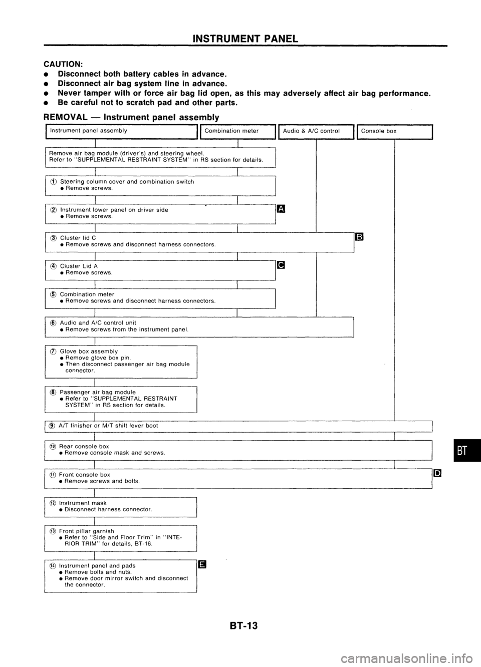
CAUTION:
• Disconnect bothbattery cablesinadvance.
• Disconnect airbag system lineinadvance.
• Never tamper withorforce airbag lidopen, asthis may adversely affectairbag performance.
• Becareful nottoscratch padandother parts.
REMOVAL -Instrument panelassembly
Instrument panelassembly
Remove airbag module (driver's) andsteering wheel.
Refer to"SUPPLEMENTAL RESTRAINTSYSTEM"inRS section fordetails.
CD
Steering columncoverandcombination switch
• Remove screws.
l6l
Instrument lowerpanel ondriver side
• Remove screws.
@
Cluster lidC
• Remove screwsanddisconnect harnessconnectors. Audio
&AIC
control
Consolebox
@
Cluster lidA
• Remove screws.
@
Combination meter
• Remove screwsanddisconnect harnessconnectors.
cID
Audio and
AIC
control unit
• Remove screwsfromtheinstrument panel.
(J)
Glove boxassembly
• Remove gloveboxpin.
• Then disconnect passengerairbag module
connector.
@
Passenger airbag module
• Refer to"SUPPLEMENTAL RESTRAINT
SYSTEM" inRS section fordetails.
@
AIT
finisher orMIT shift lever boot
@
Rear console box
• Remove consolemaskandscrews.
@
Front console box
• Remove screwsandbolts.
@
Instrument mask
• Disconnect harnessconnector.
@
Front pillargarnish
• Refer to"Side andFloor Trim" in"INTE-
RIOR TRIM" fordetails, 8T-16.
@
Instrument panelandpads
II
• Remove boltsandnuts.
• Remove doormirror switch anddisconnect
the connector.
•
8T-13
Page 238 of 1701
INTERIORTRIM
Side andFloor Trim(ConI' d)
REMOVAL -Body sidetrim
5-door hatchback
• Remove tonneau boardbefore removing bodysidetrim.
CD
Remove frontandrear seats. Referto"SEAT" fordetails, BT-35.
@
Remove frontandrear seat belts. Referto"SEAT BELTS" inRS section fordetails.
@)
Remove frontandrear kicking plates.
@
Remove dashsidelower finishers.
CID
Remove frontandrear body sidewelts.
@)
Remove frontpillar garnishes.
(f)
Remove centerpillarlower garnishes.
@
Remove centerpillarupper garnishes.
@
Remove rearparcel shelfsidefinishers.
@)
Remove rearpillar finishers.
@
Remove rearwheelhouse finishers.
@
Remove luggageroomrearplate.
@
Remove luggageroomrearfinisher.
@
Remove luggageroomsidelower finishers.
SEC. 678-749-769-799
MetalcliPGl
~:Velcro
X :Metal clip
88T050
8T-18
Page 253 of 1701
EXTERIOR
@
Front airspoiler
SEC. 960
8BT074
@
Front struttower barassembly
SEC. 401
[OJ:
N.m (kg-m, ft-lb)
8BT099
•
CAUTION:
Do not remove frontstruttower barassembly whilevehicle isjacked upwith wheels on.
8T-33