1995 NISSAN ALMERA N15 ESP
[x] Cancel search: ESPPage 997 of 1701
![NISSAN ALMERA N15 1995 Service Manual TROUBLEDIAGNOSIS -General Description
[]K]
CONSULT Reference ValueinData Monitor
Mode (Cont'd)
MONITOR ITEM
CONDITION SPECIFICATION
Steering wheelinneutral
position OFF
PW/ST SIGNAL
•Engine: NISSAN ALMERA N15 1995 Service Manual TROUBLEDIAGNOSIS -General Description
[]K]
CONSULT Reference ValueinData Monitor
Mode (Cont'd)
MONITOR ITEM
CONDITION SPECIFICATION
Steering wheelinneutral
position OFF
PW/ST SIGNAL
•Engine:](/manual-img/5/57349/w960_57349-996.png)
TROUBLEDIAGNOSIS -General Description
[]K]
CONSULT Reference ValueinData Monitor
Mode (Cont'd)
MONITOR ITEM
CONDITION SPECIFICATION
Steering wheelinneutral
position OFF
PW/ST SIGNAL
•Engine: Afterwarming up,idle theengine (forward
direction)
The steering wheelis
ON
turned
• Engine: Afterwarming up
Idle2.5-3.7 msec .
INJ PULSE •
Air conditioner switch:OFF
• Shift lever: "N"
• No-load 2,000
rpm 1.9-2.8 msec .
Idle 13-15° BTDC
IGN TIMING
ditto
2,000rpm Morethan25°BTDC
Idle 20-40%
IACV-AACIV ditto
2,000rpm
-
A/F ALPHA •Engine: Afterwarming up Maintaining
enginespeed
53-155%
at 2.000 rpm
AIR COND RLY •Air conditioner switch:OFF
-+
ON OFF
-+
ON
• Ignition switchis~urned toON (Operates for5seconds)
• Engine running andcranking ON
FUEL PUMP RLY
•When engine isstopped (stopsin1.0 seconds)
• Except asshown above OFF
Engine coolant temperature
is 94°C (201°F) orless for
AfT models. and99°C OFF
(210°F) orless for
M/T
mod-
els
• After warming upengine. idletheengine. Engine
coolant temperature
is between 95°C(203°F) and
COOLING FAN •Air conditioner switch:OFF
104°C(219°F) forA/T mod- LOW
• Vehicle stopped
elsonly
Engine coolant temperature
is 105°C (221°F) ormore for
A/T
models. and100°C HIGH
(212°F) ormore for
M/T
models
• Engine: Afterwarming up
IdleON
EGRC SOLIV •
Air conditioner switch:OFF
• Shift lever: "N"
• No-load 2.000
rpm OFF
EC-278
Page 1002 of 1701
TROUBLEDIAGNOSIS -General Description
[ill
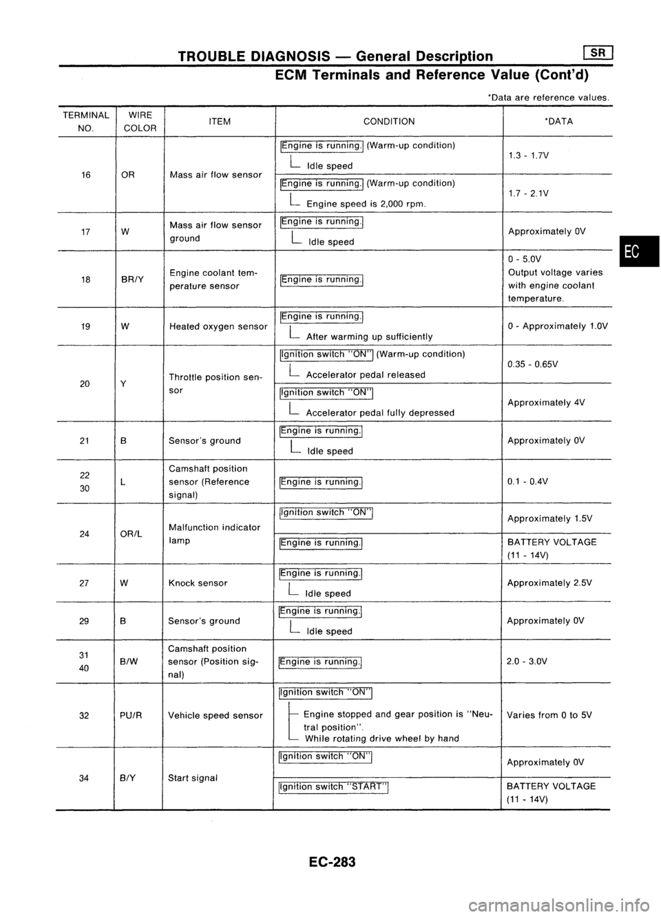
ECM Terminals andReference Value(Conl'd)
*Data arereference values.
TERMINAL WIRE
NO. COLOR ITEM
CONDITION *DATA
IEngine isrunning.1 (Warm-up condition)
1.3-1.7V
L
Idle speed
16 OR Mass
airflow sensor
IEngineisrunning.1 (Warm-up condition)
1.7-2.1V
L
Engine speedis2,000 rpm.
17 W Mass
airflow sensor IEngine
isrunning.!
ApproximatelyOV
ground
L
Idle speed
0-5.0V
18 BRIY Engine
coolant tem-
IEngineisrunning.! Output
voltage varies
perature sensor with
engine coolant
temperature.
19 W
Heatedoxygen sensor IEngine
isrunning.1
0-Approximately 1.OV
L
After warming upsufficiently
Ilgnition switch"ON"I(Warm-up condition)
0.35-0.65V
Throttle position sen-
L
Accelerator pedalreleased
20 Y
sor Ilgnitionswitch"ON"I
L
Approximately
4V
Accelerator pedalfullydepressed
21 B Sensor'sground IEngine
isrunning.1
ApproximatelyOV
L
Idle speed
22 Camshaft
position
30 L
sensor
(Reference IEngineisrunning.1 0.1
-O.4V
signal)
jlgnitionswitch"ON"!
Approximately1.5V
24 ORIL Malfunction
indicator
lamp IEngineisrunning.1 BATTERY
VOLTAGE
(11 -14V)
27 W Knock
sensor IEngine
isrunning.1
Approximately2.5V
L
Idle speed
29 B Sensor's
ground IEngine
isrunning.1
ApproximatelyOV
L
Idle speed
31 Camshaft
position
40
S/W
sensor
(Position sig-
IEngineisrunning.! 2.0
-3.0V
nal)
Ilgnitionswitch"ON"I
32 PUIR
Vehiclespeedsensor
t
Eng;ne "opped andge., po,;!;on ;,"Neo-
Variesfrom0to 5V
tral position".
While rotating drivewheel byhand
Ilgnition switch"ON"!
ApproximatelyOV
34
BIY
Start
signal
Ilgnitionswitch"START"I SA
TTERY VOLTAGE
(11 -14V)
EC-283
•
Page 1004 of 1701
![NISSAN ALMERA N15 1995 Service Manual TROUBLEDIAGNOSIS -General Description
[]K]
ECM Terminals andReference Value(Cont'd)
'Data arereference values.
TERMINAL WIRE
ITEM CONDITION
'DATA
NO. COLOR
Ilgnitionswitch"ON"I
NISSAN ALMERA N15 1995 Service Manual TROUBLEDIAGNOSIS -General Description
[]K]
ECM Terminals andReference Value(Cont'd)
'Data arereference values.
TERMINAL WIRE
ITEM CONDITION
'DATA
NO. COLOR
Ilgnitionswitch"ON"I](/manual-img/5/57349/w960_57349-1003.png)
TROUBLEDIAGNOSIS -General Description
[]K]
ECM Terminals andReference Value(Cont'd)
'Data arereference values.
TERMINAL WIRE
ITEM CONDITION
'DATA
NO. COLOR
Ilgnitionswitch"ON"I
L
For 5seconds afterturning ignition switch
"ON" Approximately
OV
104 B/P Fuelpump relay !Engine
isrunning.1
Ilgnition switch"ON"I
BATTERY VOLTAGE
L
5seconds afterturning ignitionswitch
(11-14V)
"ON" andthereafter
IEngine isrunning.1
0.6-0.8V
EGR valve
&
EVAP
.L
Engine speedis4,000 rpm.
105 P canisterpurgecontrol
solenoid valve IEngine
isrunning.1
BATTERYVOLTAGE
L
Idle speed (11
-14V)
107 IEngine
isrunning.j
B/Y ECCSground
L
Engine
ground
108 Idlespeed
!Engine isrunning.1
Approximately0.2V
L
Engine speedisbelow 3,200rpm.
Heated oxygen sensor
111 OR
heater IEngineisrunning.1
BATTERY VOLTAGE
L
Engine speedisabove 3,200rpm. (11
-14V)
IEngine isrunning.\
11-14V
L
Idle speed
113 SB IACV-AAC
valve lEngine
isrunning.1
~ Sle«;ng wheel;,be;ng I"med
2-11V
Air conditioner isoperating.
Rear window defogger switchis"ON".
Lighting switchis"ON".
!Engine isrunning.1
ApproximatelyOV
Torque converter
L
Idle speed
115 P/B clutch
solenoid valve
IEngineisrunning.1 (Warm-up condition)
(A/T
models)
L
Vehicle speedis60 km/h (37MPH) or BA
TTERY VOLTAGE
(11 -14V)
more in"D" position
116 BIY ECCS
ground IEngine
isrunning.1
Engineground
L
Idle speed
EC-285
•
Page 1008 of 1701
TROUBLEDIAGNOSIS FOROTC11
Rotor plate
SEF6138
180
0
signal slitfor NO.1 cylinder
\\\\""I"~'11111
1
0
signal slit
\\\\\ d'"
/11;
:£
';\'0\
I//..;:
#'
/%
$ ~
180
0
signal slit
f
0
%
o
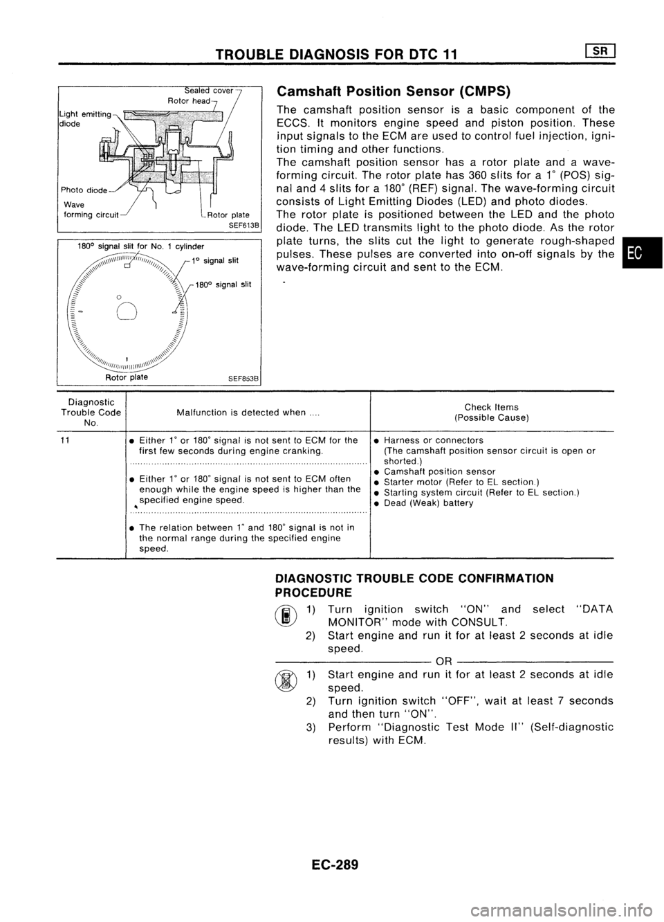
Camshaft
PositionSensor(CMPS)
The camshaft positionsensorisabasic component ofthe
ECCS. Itmonitors enginespeedandpiston position. These
input signals tothe ECM areused tocontrol fuelinjection, igni-
tion timing andother functions.
The camshaft positionsensorhasarotor plate andawave-
forming circuit.Therotor plate has360slits fora
1"
(POS) sig-
nal and 4slits fora180
0
(REF) signal. Thewave-forming circuit
consists ofLight Emitting Diodes(LED)andphoto diodes.
The rotor plate ispositioned betweentheLED andthephoto
diode. TheLED transmits lighttothe photo diode. Asthe rotor
plate turns, theslits cutthe light togenerate rough-shaped •
pulses. Thesepulses areconverted intoon-off signals bythe
wave-forming circuitandsent tothe ECM.
Rotor plate
SEF8638
Diagnostic
Trouble Code
No.
11
Malfunction
isdetected when....
• Either 1
0
or 180
0
signal isnot sent toECM forthe
first fewseconds duringengine cranking.
• Either
r
or 180" signal isnot sent toECM often
enough whiletheengine speedishigher thanthe
specified enginespeed.
~
• The relation between rand180
0
signal isnot in
the normal rangeduring thespecified engine
speed. Check
Items
(Possible Cause)
• Harness orconnectors
(The camshaft positionsensorcircuitisopen or
shorted.)
• Camshaft positionsensor
• Starter motor(Refer toEL section.)
• Starting systemcircuit(RefertoEL section.)
• Dead (Weak) battery
3)
@
1)
2)
DIAGNOSTIC
TROUBLECODECONFIRMATION
PROCEDURE
rif\
1)Turn ignition switch"ON"andselect "DATA
~ MONITOR" modewithCONSULT.
2) Start engine andrunitfor atleast 2seconds atidle
speed.
---------- OR----------
Start engine andrunitfor atleast 2seconds atidle
speed.
Turn ignition switch"OFF", waitatleast 7seconds
and then turn"ON".
Perform "Diagnostic TestMode II"(Self-diagnostic
results) withECM.
EC-289
Page 1028 of 1701
TROUBLEDIAGNOSIS FORDTC43
SEF089K Throttle
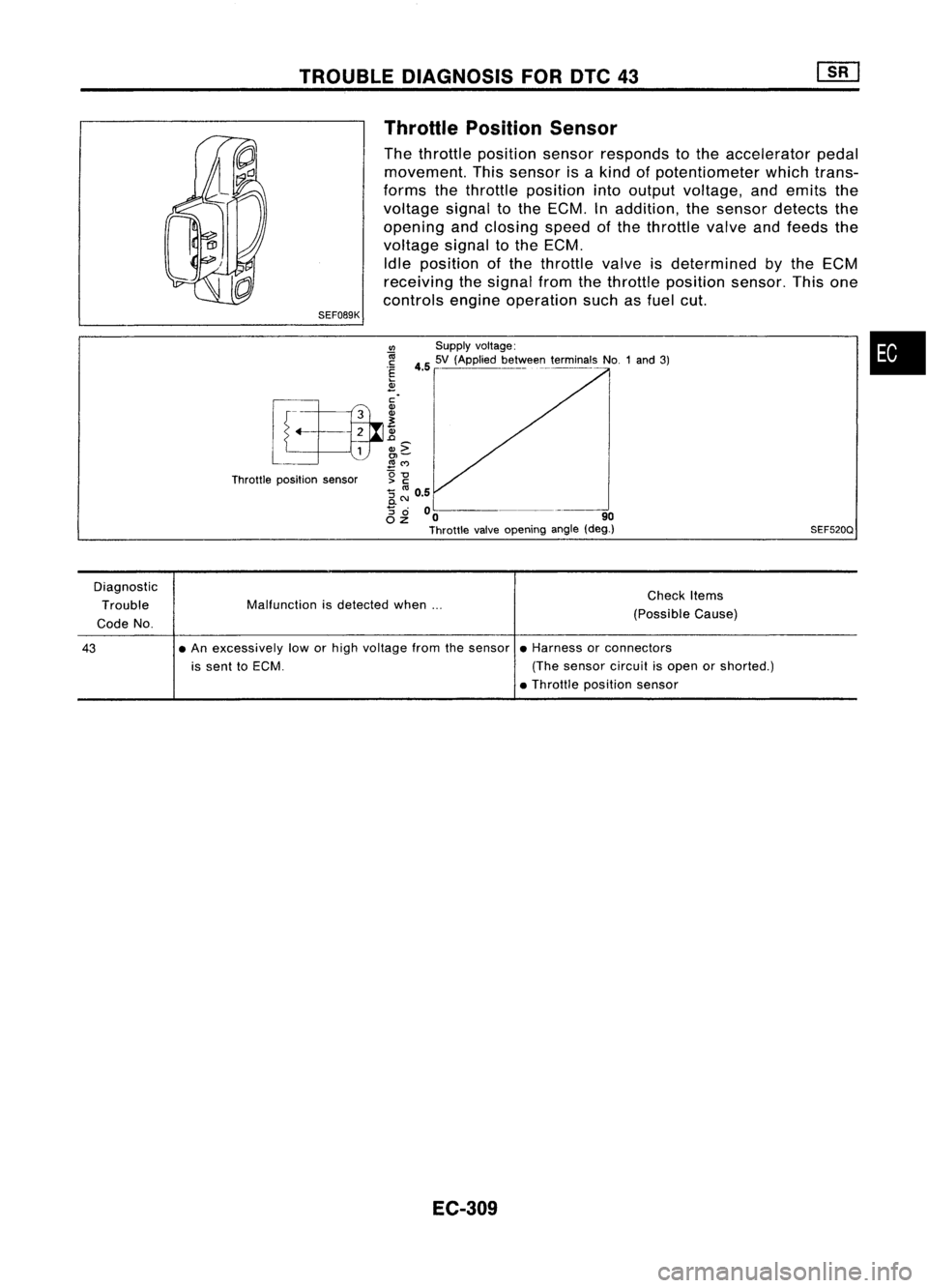
Position Sensor
The throttle position sensorresponds tothe accelerator pedal
movement. Thissensor isakind ofpotentiometer whichtrans-
forms thethrottle position intooutput voltage, andemits the
voltage signaltothe ECM. Inaddition, thesensor detects the
opening andclosing speedofthe throttle valveandfeeds the
voltage signaltothe ECM.
Idle position ofthe throttle valveisdetermined
by
the ECM
receiving thesignal fromthethrottle position sensor.Thisone
controls engineoperation suchasfuel cut.
•
SEF520Q
VI
Supplyvoltage:
~ 4.55V (Applied be~VoIee~_terminals NO.1and3)
.~
2
[f~.. ~
L
L
1
&c
~ ~M
Throttle position sensor g
-g
:; ~ 0.5
0.
8 ~
00 -~---_. 90
Throttle valveopening angle(deg.)
Diagnostic Trouble
Code No. Malfunction
isdetected when... Check
Items
(Possible Cause)
43
•
An excessively loworhigh voltage fromthesensor •Harness orconnectors
is sent toECM. (Thesensor circuitisopen orshorted.)
• Throttle position sensor
EC-309
Page 1029 of 1701
TROUBLEDIAGNOSIS FORDTC43
Throttle Position Sensor(Cont'd)
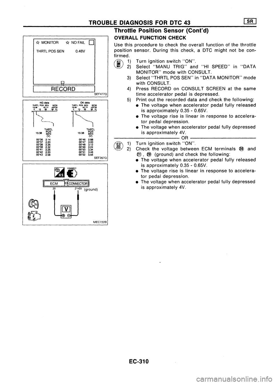
OVERALL FUNCTION CHECK
"*
MONITOR *NO FAIL
0
THRTL
pas
SEN 0.48V
I- I~-----..l
~-R-E-CO-R-D-~I
SEF477QUse
thisprocedure tocheck theoverall function ofthe throttle
position sensor.Duringthischeck, aDTC might notbecon-
firmed.
rij\
1)
~ 2)
Turn
ignition switch"ON".
Select "MANU TRIG"and"HISPEED" in"DATA
MONITOR" modewithCONSULT.
3) Select "THRTL POSSEN" in"DATA MONITOR" mode
with CONSULT.
4) Press RECORD onCONSULT SCREENatthe same
time accelerator pedalisdepressed.
5) Print outthe recorded dataandcheck thefollowing:
• The voltage whenaccelerator pedalfullyreleased
is approximately 0.35-0.65V .
• The voltage riseislinear inresponse toaccelera-
tor pedal depression .
• The voltage whenaccelerator pedalfullydepressed
is approximately 4V.
---------- OR----------
1) Turn ignition switch"ON",
2) Check thevoltage between ECMterminals
@J
and
@,
@
(ground) andcheck thefollOWing:
• The voltage whenaccelerator pedalfullyreleased
is approximately 0.35-0.65V.
• The voltage riseislinear inresponse toaccelera-
tor pedal depression.
• The voltage whenaccelerator pedalfullydepressed
is approximately 4V,
THRTL
15:38 ~~~
(V)
00"46 2.88
00"47 3.00
00"48 3.12
00"49 3.24
00"50 3.34
00"51 3.46
00"52 3.56
SEF267Q
OK
data
THRTL
pos
SEN
OO~
~~~'3. 1
'g;v :":'
................. 1
MEC7228
~i)
ECM
El'coNNEcTORII
LelJ
(9"oodl
II
THRTl
15:38 ~~~
(V)
00"36 214
00"37 2.20
00"38 2.26
00"39 2.32
00"41 2.26
00"42 2.20
00"43 2.58
NG
data
THFm.
pos
SEN 00"00
'~U. '3
~v ~:'
•
")
•...•..•..• 1
EC-310
Page 1034 of 1701
•
DIAGNOSTIC
PROCEDURE
INSPECTION START
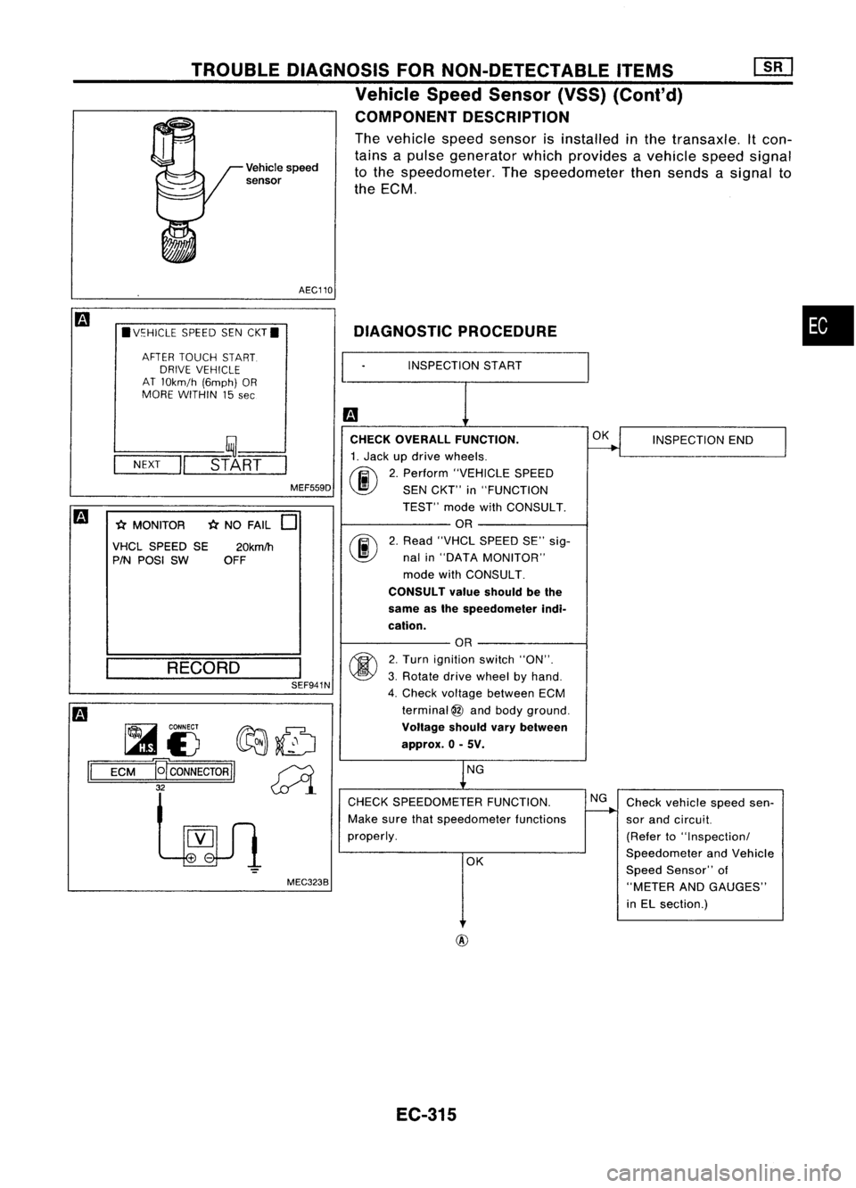
Vehicle
speed
sensor
TROUBLE
DIAGNOSIS FORNON-DETECTABLE ITEMS
Vehicle SpeedSensor (VSS)(Conl'd)
COMPONENT DESCRIPTION
The vehicle speedsensor isinstalled inthe transaxle. Itcon-
tains apulse generator whichprovides avehicle speedsignal
to the speedometer. Thespeedometer thensends asignal to
the ECM.
AEC110
• V~HICLE SPEEDSENCKT.
AFTER TOUCH START.
DRIVE VEHICLE
AT lOkm!h (6mph)OR
MORE WITHIN 15
see
L--- __ '~----'
-N-EX-T
-1I=~_s-T_A~R=T==
MEF559D
*
MONITOR
*
NO FAIL
0
VHCL SPEED SE20kmlh
PIN POSI SW OFF CHECK
OVERALL FUNCTION.
1. Jack updrive wheels.
fi\
2.Perform "VEHICLE SPEED
~ SENCKT" in"FUNCTION
TEST" modewithCONSULT.
OR
rif\
2.Read "VHCl SPEED SE"sig-
~ nalin"DATA MONITOR"
mode withCONSULT.
CONSULT valueshould bethe
same asthe speedometer indi-
cation.
OK
INSPECTION END
RECORD SEF941N
~ CONNECT
f?Ft::J:.~
~£) ~~
1='
=E=CM=-g
CONNECTOR
II~
32
~l
MEC3238
OR
2. Turn ignition switch"ON".
3. Rotate drivewheel byhand.
4. Check voltage between ECM
terminal
@
and body ground.
Voltage shouldvarybetween
approx. 0-5V.
NG
CHECK SPEEDOMETER FUNCTION.
Make surethatspeedometer functions
properly.
OK NG
Check vehicle speedsen-
sor and circuit.
(Refer to"Inspection!
Speedometer andVehicle
Speed Sensor" of
"METER ANDGAUGES"
in El section.)
@
EC-315
Page 1038 of 1701
TROUBLEDIAGNOSIS FORNON-DETECTABLE ITEMS
Exhaust GasRecirculation (EGR)Valveand
EVAP Canister PurgeControl
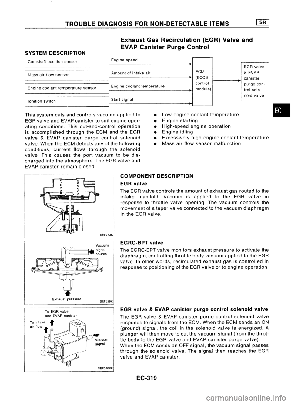
SYSTEM DESCRIPTION
I
Camshaft positionsensor
I
Engine speed
EGRvalve
I
Mass
airflow sensor
I
Amount ofintake air ECM
&
EVAP
(ECCS canister
I
~Engine
coolanttemperature control
purgecon-
Engine coolant temperature sensor
module)trolsole-
I
noid
valve
Ignition switch
I
Start signal
I
This system cutsandcontrols vacuumappliedto
EGR valve andEVAP canister tosuit engine oper-
ating conditions. Thiscut-and-control operation
is accomplished throughtheECM andtheEGR
valve
&
EVAP canister purgecontrol solenoid
valve. WhentheECM detects anyofthe following
conditions, currentflowsthrough thesolenoid
valve. Thiscauses theport vacuum tobe dis-
charged intotheatmosphere. TheEGR valve and
EVAP canister remainclosed.
•
•
•
•
•
•
Low
engine coolant temperature
Engine starting
High-speed engineoperation
Engine idling
Excessively highengine coolant temperature
Mass airflow sensor malfunction
•
Exhaust pressure COMPONENT
DESCRIPTION
EGR valve
The EGR valve controls theamount ofexhaust gasrouted tothe
intake manifold. Vacuumisapplied tothe EGR valve in
response tothrottle valveopening. Thevacuum controls the
movement ofataper valve connected tothe vacuum diaphragm
in the EGR valve.
SEF783K EGRC-BPT valve
The EGRC-BPT valvemonitors exhaustpressure toactivate the
diaphragm, controllingthrottlebodyvacuum appliedtothe EGR
valve. Inother words, recirculated exhaustgasiscontrolled in
response topositioning ofthe EGR valve ortoengine operation.
SEF529K
~ Vacuumsignal
SEF240PE EGR
valve
&
EVAP canister purgecontrol solenoid valve
The EGR valve
&
EVAP canister purgecontrol solenoid valve
responds tosignals fromtheECM. When theECM sends anON
(ground) signal,thecoil inthe solenoid valveisenergized. A
plunger willthen move tocut the vacuum signal(fromthethrot-
tle body tothe EGR valve andEVAP canister purgevalve).
When theECM sends anOFF signal, thevacuum signalpasses
through thesolenoid valve.Thesignal thenreaches theEGR
valve andEVAP canister.
EC-319