Page 1206 of 1701
•:Mating mark(different color) 16
rollers
SEM129F TIMING
CHAIN
@K]
Installation
(Cont'd)
19. Assemble camshaftsprocketwithchain.
• Set timing chainbyaligning matingmarkswiththose of
camshaft sprockets.
• Make suresprocket's matingmarksfaceengine front.
20. Install camshaft sprocketbolts.
• Apply newengine oiltobolt threads andseat surface .
•
SEM657D
2.0.3.0
mm
(0.079 -0.118 In)
21.
Install upperchaintensioner.
• Before installing chaintensioner, insertasuitable pininto
pin hole ofchain tensioner.
• After installing chaintensioner, removethepin.
22. Install lowerchaintensioner.
CAUTION:
• Check noproblems occurwhenengine isrotated.
• Make surethatNo.1piston isset atTOC onitscompres-
sion stroke.
• Make sureofthe direction ofthe gasket beforeinstalling
lower chaintensioner.
23. Apply liquidgasket tothermostat housing.
• Use Genuine LiquidGasket orequivalent.
24. Install thermostat housing.
25. Install waterpump pulley.
EM-27
Page 1209 of 1701
OILSEAL REPLACEMENT
KV10l07902
VALVE
OilSEAL
1. Remove rockercover.
2. Remove camshaft.
3. Remove valvespring. Referto"CYLINDER HEAD".
4. Remove valveoilseal withasuitable tool.
Piston concerned shouldbeset atTOC toprevent valvefrom
falling.
5. Apply engine oiltonew valve oilseal andinstall itwith Tool.
SEM136D
10.5
mm
(0.413 In)
SEM137D
FRONTOilSEAL
1. Remove thefollowing parts:
• Engine undercover
• Right-side splashcover
• Alternator andpower steering drivebelts
• Crankshaft pulley
2. Remove frontoilseal from front cover.
Be careful nottodamage oilseal portion.
• Install newoilseal inthe direction shown.
Engine /',
inside
Y
~
Engine
Youtside
Oil seal lip Dust
seal
lip
SEM715A EM-30
Page 1213 of 1701

CYLINDERHEAD
CAUTION:
• When installing camshaft, oilseals orother sliding parts,
lubricate contacting surfaceswithnewengine oil.
• When tightening cylinderheadbolts, camshaft sprocket
bolts andcamshaft bracketbolts,lubricate threadportions
and seat surfaces ofbolts withnewengine oil.
• Attach tagstovalve lifters soas not tomix them up.
Removal
• This removal isthe same procedure asthose fortiming
chain. Referto"Removal" in"TIMING CHAIN"(EM-20).
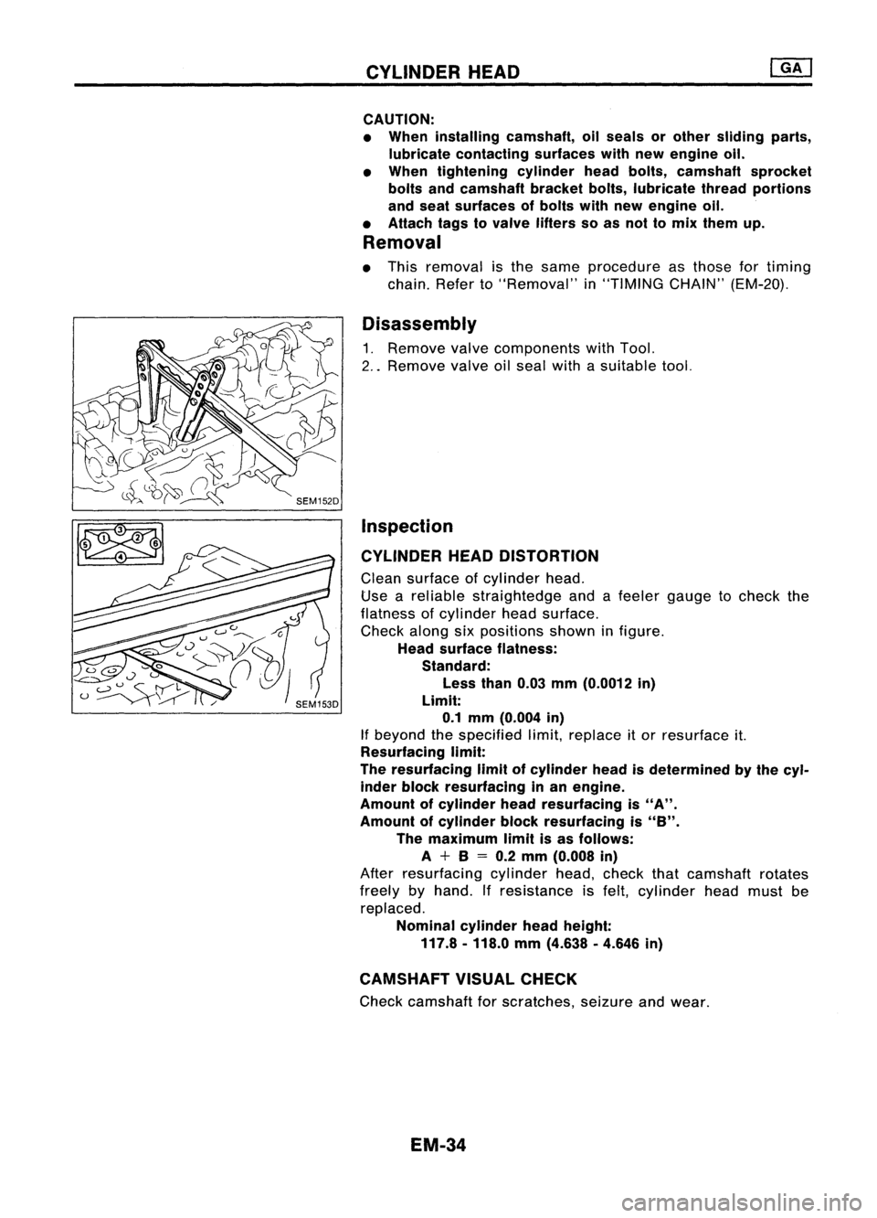
Disassembly
1. Remove valvecomponents withTool.
2 .. Remove valveoilseal withasuitable tool.
Inspection
CYLINDER HEADDISTORTION
Clean surface ofcylinder head.
Use areliable straightedge andafeeler gauge tocheck the
flatness ofcylinder headsurface.
Check alongsixpositions showninfigure.
Head surface flatness:
Standard:
Less than0.03mm(0.0012 in)
Limit: 0.1 mm (0.004 in)
If beyond thespecified limit,replace itor resurface it.
Resurfacing limit:
The resurfacing limitofcylinder headisdetermined bythe cyl-
inder block resurfacing inan engine.
Amount ofcylinder headresurfacing is
"A".
Amount ofcylinder blockresurfacing is
"8".
The maximum limitisas follows:
A +8
=
0.2 mm (0.008 in)
After resurfacing cylinderhead,check thatcamshaft rotates
freely byhand. Ifresistance isfelt, cylinder headmust be
replaced.
Nominal cylinderheadheight:
117.8 -118.0 mm(4.638 .4.646 in)
CAMSHAFT VISUALCHECK
Check camshaft forscratches, seizureandwear.
EM-34
Page 1218 of 1701

T(Margin thickness)
--1,-
ml
a
III' ~
o
~-
-L
d
SEM8928
I
.\
SEM188A
CYLINDER
HEAD
Inspection (Conl'd)
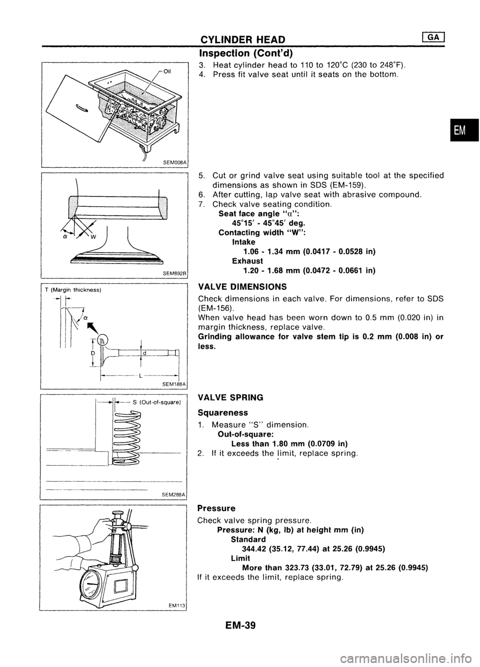
3. Heat cylinder headto110 to120°C (230to248°F).
4. Press fitvalve seatuntilitseats onthe bottom .
5. Cut orgrind valve seatusing suitable toolatthe specified
dimensions asshown inSOS (EM-159).
6. After cutting, lapvalve seatwithabrasive compound.
7. Check valveseating condition.
Seat faceangle "a":
45°15' -45°45' deg.
Contacting width"W":
Intake
1.06 -1.34 mm(0.0417 -0.0528 in)
Exhaust
1.20 -1.68 mm(0.0472 -0.0661 in)
VALVE DIMENSIONS
Check dimensions ineach valve. Fordimensions, refertoSOS
(EM-156).
When valveheadhasbeen worn down to0.5 mm (0.020 in)in
margin thickness, replacevalve.
Grinding allowance forvalve stemtipis0.2 mm (0.008 in)or
less.
•
SEM288A VALVE
SPRING
Squareness
1. Measure "S"dimension.
Out-of-square: Less than1.80mm(0.0709 in)
2. Ifitexceeds thelimit, replace spring.
EM113
Pressure
Check valvespring pressure.
Pressure: N(kg, Ib)atheight mm(in)
Standard 344.42 (35.12, 77.44)at25.26 (0.9945)
Limit More than323.73 (33.01, 72.79)at25.26 (0.9945)
If itexceeds thelimit, replace spring.
EM-39
Page 1219 of 1701

SEM160DCYLINDER
HEAD
Inspection (Cont'd)
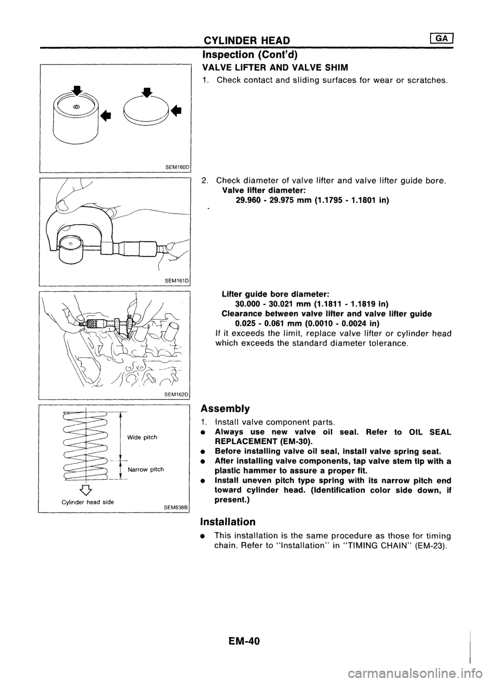
VALVE LIFTER ANDVALVE SHIM
1. Check contact andsliding surfaces forwear orscratches.
SEM161D
SEM162D
2.
Check diameter ofvalve lifterandvalve lifterguide bore.
Valve lifterdiameter:
29.960 •29.975 mm(1.1795 •1.1801 in)
Lifter guide borediameter:
30.000 -30.021 mm(1.1811 .1.1819 in)
Clearance betweenvalvelifterandvalve lifterguide
0.025 -0.061 mm(0.0010 -0.0024 in)
If
it
exceeds thelimit, replace valvelifterorcylinder head
which exceeds thestandard diameter tolerance.
o
Cylinder headside Wide
pitch
Narrow pitch
SEM638B
Assembly
1. Install valvecomponent parts.
• Always usenew valve oilseal. Refer toOIL SEAL
REPLACEMENT (EM-30).
• Before installing valveoilseal, install valvespring seat.
• After installing valvecomponents, tapvalve stemtipwith a
plastic hammer toassure aproper fit.
• Install uneven pitchtypespring withitsnarrow pitchend
toward cylinder head.(Identification colorsidedown, if
present.)
Installation
• This installation isthe same procedure asthose fortiming
chain. Referto"Installation" in"TIMING CHAIN"(EM-23).
EM-40
Page 1225 of 1701
ENGINEREMOVAL
mJ
Removal (Cont'd)
• Disconnect controlrodand support rodfrom transaxle.
(M/T
models)
Control rod:
to:J:
14-18 N.m (1.4-1.8 kg-m, 10-13 ft-Ib)
Support rod:
to:J:
35-47 N.m (3.6-4.8 kg-m, 26-35 ft-Ib)
• Disconnect controlcablefromtransaxle.
(A/Tmodels)
• Center member
• Front exhaust tube
• Stabilizer
• Cooling fan
• Radiator
• Cylinder headfrontmounting bracket
• Remove airduct anddisconnect wires,harness, pipes,
hoses andsoon.
8. Lift upengine slightly anddisconnect orremove allengine
mountings.
When liftingengine, becareful nottohit itagainst adjacent
parts, especially againstbraketubesandbrake master cylin-
der.
9. Remove enginewithtransaxle asshown.
Installation
When installing theengine, adjusttheheight ofbuffer rodas
shown. (ForM/T)
• Installation isthe reverse orderofremoval.
EM-46
Page 1232 of 1701

Mainjournal andpinjournal
R
SEM588ACYLINDER
BLOCK
[ill
Inspection (Conl'd)
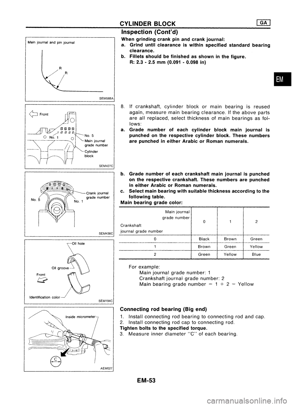
When grinding crankpinand crank journal:
a. Grind untilclearance iswithin specified standardbearing
clearance.
b. Fillets should befinished asshown inthe figure.
R: 2.3 -2.5 mm (0.091 -0.098 in)
•
~ Front
No.5
Main journal
grade number
Cylinder
block
SEM427C
8.
Ifcrankshaft, cylinderblockormain bearing isreused
again, measure mainbearing clearance. Ifthe above parts
are allreplaced, selectthickness ofmain bearings asfol-
lows:
a. Grade number ofeach cylinder blockmainjournal is
punched onthe respective cylinderblock.These numbers
are punched ineither Arabic orRoman numerals.
b. Grade number ofeach crankshaft mainjournal ispunched
on the respective crankshaft. Thesenumbers arepunched
in either Arabic orRoman numerals.
c. Select mainbearing withsuitable thickness according tothe
following table.
Main bearing gradecolor:
Main journal
grade number
0
1
2
Crankshaft
journal gradenumber
0
Black
Brown Green
1
BrownGreenYellow
2
GreenYellow Blue
Crank
journal
grade number
SEM436C
\i1hOle
o,.",,!f0
Front ~~
Q
I\}:J
Identification color~
SEM194C
For
example:
Main journal gradenumber: 1
Crankshaft journalgradenumber: 2
Main bearing gradenumber
=
1
+
2 Yellow
)=====
.-:::::::======_ ..
;::..----
AEM027Connecting
rodbearing (Bigend)
1. Install connecting rodbearing toconnecting rodand cap.
2. Install connecting rodcap toconnecting rod.
Tighten boltstothe specified torque.
3. Measure innerdiameter "C"ofeach bearing.
EM-53
Page 1233 of 1701
![NISSAN ALMERA N15 1995 Service Manual CYLINDERBLOCK .@K]
Inspection (Cont'd)
4. Measure outerdiameter "Op"ofeach crankshaft pinjour-
nal.
5. Calculate connecting rodbearing clearance.
Connecting rodbearing clearance
=
C-Dp
St NISSAN ALMERA N15 1995 Service Manual CYLINDERBLOCK .@K]
Inspection (Cont'd)
4. Measure outerdiameter "Op"ofeach crankshaft pinjour-
nal.
5. Calculate connecting rodbearing clearance.
Connecting rodbearing clearance
=
C-Dp
St](/manual-img/5/57349/w960_57349-1232.png)
CYLINDERBLOCK .@K]
Inspection (Cont'd)
4. Measure outerdiameter "Op"ofeach crankshaft pinjour-
nal.
5. Calculate connecting rodbearing clearance.
Connecting rodbearing clearance
=
C-Dp
Standard:
0.014 -0.039 mm(0.0006 •0.0015 in)
Limit: 0.1mm (0.004 in)
6. Ifitexceeds thelimit, replace bearing.
7. Ifclearance cannotbeadjusted withinthestandard ofany
bearing, grindcrankshaft journalanduseundersized bear-
ing. Refer tostep 7of "BEARING CLEARANCE -Main
bearing" (EM-52).
CONNECTING RODBUSHING CLEARANCE (Smallend)
1. Measure innerdiameter "C"ofbushing.
8.
Ifbearing, crankshaft orconnecting rodisreplaced witha
new one, select connecting rodbearing according tothe
following table.
Connecting rodbearing gradenumber:
Grade numbers arepunched ineither Arabic orRoman numer-
als.
Method B(Using plastigage)
CAUTION:
• Donot turn crankshaft orconnecting rodwhile plastigage is
being inserted.
• When bearing clearance exceedsthespecified limit,ensure
that theproper bearing hasbeen installed. Thenifexces-
sive bearing clearance exists,useathicker mainbearing or
undersized bearingsothat thespecified bearingclearance
is obtained.
Brown
Green
Connecting
rodbearing
grade color
a
1
2
Crank
pingrade color
SEM437C
EM-54