1995 NISSAN ALMERA N15 ESP
[x] Cancel search: ESPPage 1333 of 1701
EM03470000orsuitable tool CYLINDER
BLOCK
lliJ
Assembly
(Conl'd)
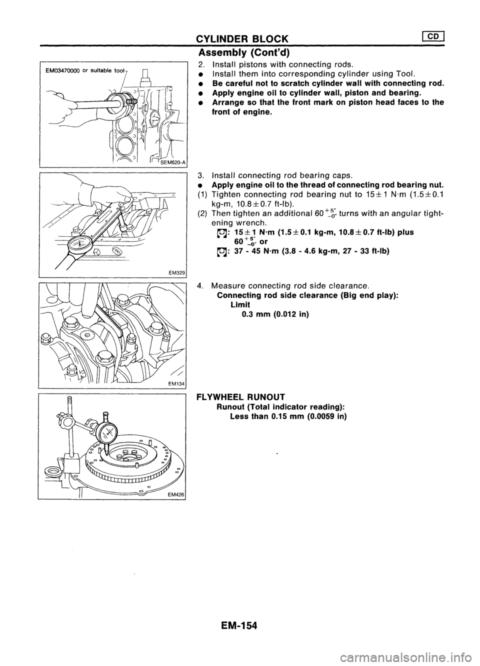
2. Install pistons withconnecting rods.
• Install themintocorresponding cylinderusingTool.
• Becareful nottoscratch cylinder wallwithconnecting rod.
• Apply engine oiltocylinder wall,piston andbearing.
• Arrange sothat thefront mark onpiston headfaces tothe
front ofengine.
3. Install connecting rodbearing caps.
• Apply engine oiltothe thread ofconnecting rodbearing nut.
(1) Tighten connecting rodbearing nutto15:1:1 N'm(1.5:1:0.1
kg-m, 10.8:1:0.7ft-Ib).
(2) Then tighten anadditional 60
+_~'.
turns withanangular tight-
ening wrench.
~: 15:1:1 N'm(1.5:1:0.1 kg-m,10.8:1:0.7 ft-Ib)plus
60+'::;.
or
~: 37-45 N'm (3.8-4.6 kg-m, 27-33 ft-Ib)
4. Measure connecting rodside clearance.
Connecting rodside clearance (Bigendplay):
Limit
0.3
mm (0.012 in)
FLYWHEEL RUNOUT
Runout (Totalindicator reading):
Less than0.15mm(0.0059 in)
EM-154
Page 1351 of 1701
Valvespring SERVICE
DATAANDSPECIFICATIONS (50S)
Inspection andAdjustment (Cont'd)
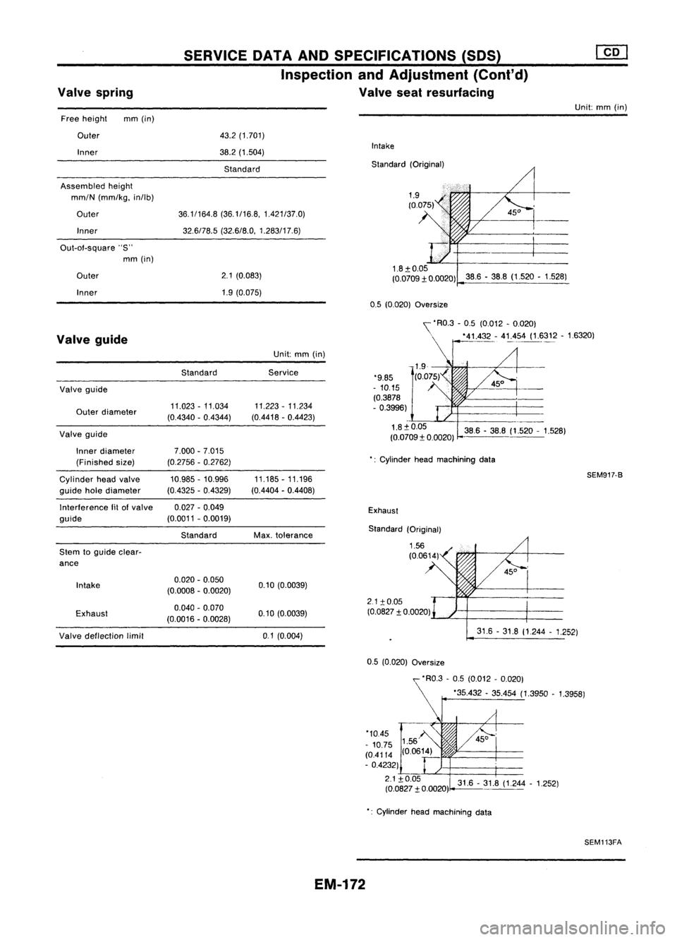
Valve seatresurfacing
Unit:mm(in)
Free height mm(in)
Outer
Inner
Assembled height
mm/N (mm/kg, in/lb)
Outer Inner
Out-of-square "S"
mm (in)
Outer
Inner
43.2
(1.701)
38.2 (1.504)
Standard
36.1/164.8 (36.1/16.8,1.421/37.0)
32.6/78.5 (32.6/8.0, 1.283/17.6)
2.1 (0.083)
1.9 (0.075)
Intake
Standard (Original)
1.8:t 0.05
(0.0709:t 0.0020) 38.6-38.8 (1.520 -1.528)
0.5 (0.020)
Oversize
Exhaust
2.1 :to.05
(0.0827 :t0.0020)
Valve
guide
Valve guide
Outer diameter
Valve guide
Inner diameter
(Finished size)
Cylinder headvalve
guide holediameter
Interference fitofvalve
guide
Stem toguide clear-
ance
Intake
Exhaust Standard
11.023 -11.034
(0.4340 -0.4344)
7.000 -7.015
(0.2756 -0.2762)
10.985 -10.996
(0.4325 -0.4329)
0.027 -0.049
(0.0011 -0.0019)
Standard
0.020 -0.050
(0.0008 -0.0020)
0.040 -0.070
(0.0016 -0.0028)
Unit:
mm(in)
Service
11.223 -11.234
(0.4418 -0.4423)
11.185 -11.196
(0.4404 -0.4408)
Max. tolerance
0.10 (0.0039)
0.10 (0.0039) '\
'RO.3 -0.5 (0.012 -0.020)
. '41.4_~- 4!:.,454(1.~312 -16320)
'9.85
- 10.15
(0.3878
- 0.3996)
1.8:t0.05 38.6-38.8 (1.520 -1.528)
(0.0709:t 0.0020)
': Cylinder headmachining data
SEM917-B
Standard (Original)
Valve deflection limit
0.1(0.004) 31.6
-31.8 (1.244 -1.252)
31.6 -31.8 (1.244 -1.252)
0.5
(0.020)
Oversize
,- 'RO.3 -0.5 (0.012 -0.020)
r
'35.432 -35.454 (1.3950 -1.3958)
'10.45
- 10.75
(0.4114 (0.0614)
- 0.4232)
2.1:t0.05
(0.0827 :t0.0020)
Cylinder headmachining data
SEM113FA
EM-172
Page 1358 of 1701
SEF289HSGI233
SGI234 PRECAUTIONS
General Precautions (Cont'd)
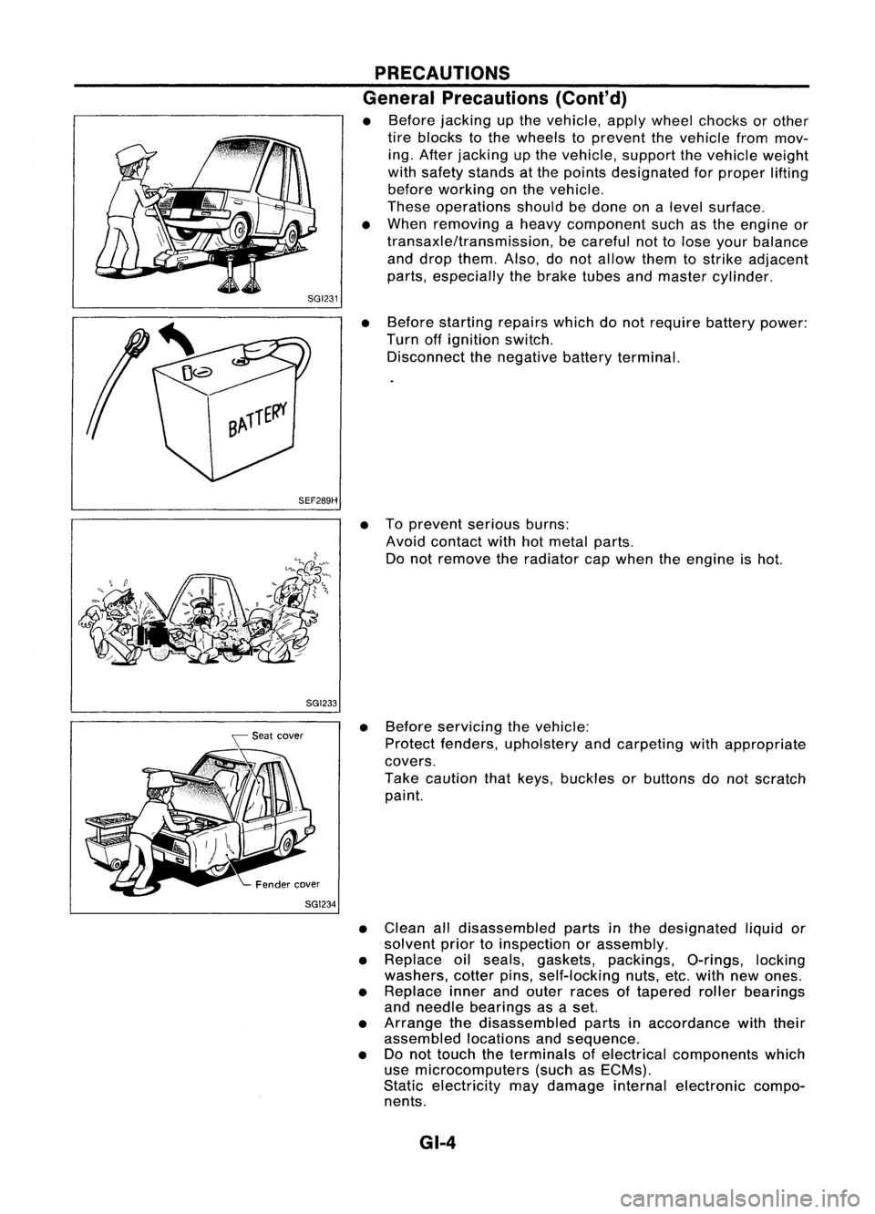
• Before jacking upthe vehicle, applywheel chocks orother
tire blocks tothe wheels toprevent thevehicle frommov-
ing. After jacking upthe vehicle, supportthevehicle weight
with safety stands atthe points designated forproper lifting
before working onthe vehicle.
These operations shouldbedone onalevel surface.
• When removing aheavy component suchasthe engine or
transaxle/transmission, becareful nottolose your balance
and drop them. Also,donot allow themtostrike adjacent
parts, especially thebrake tubesandmaster cylinder.
• Before starting repairswhichdonot require batterypower:
Turn offignition switch.
Disconnect thenegative batteryterminal.
• Toprevent seriousburns:
Avoid contact withhotmetal parts.
Do not remove theradiator capwhen theengine ishot.
• Before servicing thevehicle:
Protect fenders, upholstery andcarpeting withappropriate
covers.
Take caution thatkeys, buckles orbuttons donot scratch
paint.
• Clean alldisassembled partsinthe designated liquidor
solvent priortoinspection orassembly.
• Replace oilseals, gaskets, packings, O-rings,locking
washers, cotterpins,self-locking nuts,etc.with newones.
• Replace innerandouter races oftapered rollerbearings
and needle bearings asaset.
• Arrange thedisassembled partsinaccordance withtheir
assembled locationsandsequence.
• Donot touch theterminals ofelectrical components which
use microcomputers (suchasECMs).
Static electricity maydamage internalelectronic compo-
nents.
GI-4
Page 1365 of 1701
HOWTOREAD WIRING DIAGRAMS
Description
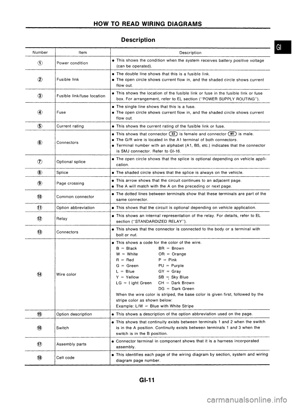
Number Item Description
CD
Power
condition •
This shows thecondition whenthesystem receives batterypositive voltage
(can beoperated) .
• The double lineshows thatthisisafusible link.
@
Fusiblelink
•The open circle shows current flowin,and theshaded circleshows current
flow out.
link/fuse location •
This shows thelocation ofthe fusible linkorfuse inthe fusible linkorfuse
box. Forarrangement, refertoEL section ("POWER SUPPLYROUTING") .
• The single lineshows thatthisisafuse.
@
Fuse
•The open circle shows current flowin,and theshaded circleshows current
flow out.
CID
Current
rating
•This shows thecurrent ratingofthe fusible linkorfuse .
• This shows thatconnector
@)
isfemale andconnector
@
ismale .
@
Connectors •
The G/R wire islocated inthe A1 terminal ofboth connectors.
• Terminal numberwithanalphabet (A1, B5, etc.) indicates thattheconnector
is SMJ connector. RefertoGI-16 .
rJ)
Optionalsplice •
The open circle shows thatthesplice isoptional depending onvehicle appli-
cation.
@
Splice •The shaded circleshows thatthesplice isalways onthe vehicle.
@
Page
crossing •
This arrow shows thatthecircuit continues toan adjacent page.
• The Awill match withtheAon the preceding ornext page .
@)
Commonconnector •
The dotted linesbetween terminals showthatthese terminals arepart ofthe
same connector.
@
Option
abbreviation •This shows thatthecircuit isoptional depending onvehicle application.
@
Relay •
This shows aninternal representation ofthe relay. Fordetails, refertoEL
section ("STANDARDIZED RELAY").
@
Connectors •
This shows thattheconnector isconnected tothe body oraterminal with
bolt ornut.
• This shows acode forthe color ofthe wire.
B
=
Black BR
=
Brown
W
=
White OR
=
Orange
R
=
Red P
=
Pink
G
=
Green PU
=
Purple
@
Wire
color L
=
Blue GY
=
Gray
Y
=
Yellow SB
=:
Sky Blue
LG
=
Light Green CH
=
Dark Brown
DG
=
Dark Green
When thewire color isstriped, thebase color isgiven first,followed bythe
stripe colorasshown below:
Example: LlW
=
Blue withWhite Stripe
@
Optiondescription •
This shows adescription ofthe option abbreviation usedonthe page.
• This shows thatcontinuity existsbetween terminals 1and 2when theswitch
@)
Switch is
inthe Aposition. Continuity existsbetween terminals 1and 3when the
switch isinthe Bposition .
@
Assembly
parts •
Connector terminalincomponent showsthatitis aharness incorporated
assembly .
@
Cell
code •
This identifies eachpage ofthe wiring diagram bysection, systemandwiring
diagram pagenumber.
GI-11
•
Page 1366 of 1701
HOWTOREAD WIRING DIAGRAMS
Description (Cont'd)
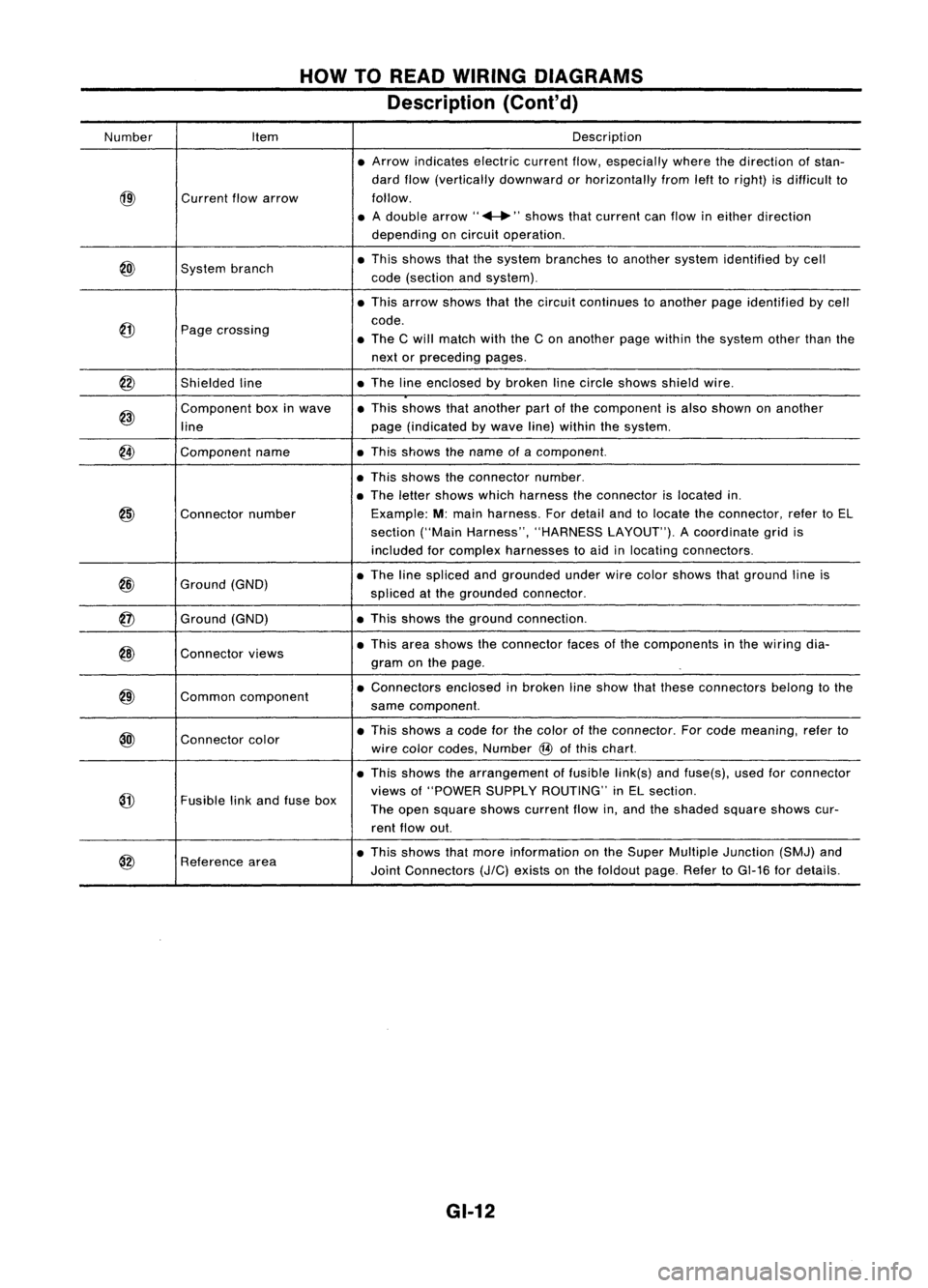
Number Item Description
• Arrow indicates electriccurrentflow,especially wherethedirection ofstan-
dard flow(vertically downward orhorizontally fromlefttoright) isdifficult to
@)
Current
flowarrow follow.
• Adouble arrow" ...."shows thatcurrent canflow ineither direction
depending oncircuit operation .
@)
System
branch •
This shows thatthesystem branches toanother systemidentified bycell
code (section andsystem) .
• This arrow shows thatthecircuit continues toanother pageidentified bycell
@
code.
Page crossing
•The Cwill match withtheCon another pagewithin thesystem otherthanthe
next orpreceding pages.
@
Shieldedline •
The lineenclosed bybroken linecircle shows shieldwire.
@)
Component
boxinwave •
This shows thatanother partofthe component isalso shown onanother
line page
(indicated bywave line)within thesystem.
@
Component
name •This shows thename ofacomponent.
• This shows theconnector number.
• The letter shows whichharness theconnector islocated in.
@)
Connector
number Example:
M:main harness. Fordetail andtolocate theconnector, refertoEL
section ("MainHarness", "HARNESS LAYOUT").Acoordinate gridis
included forcomplex harnesses toaid inlocating connectors .
@
Ground
(GND) •
The linespliced andgrounded underwirecolor shows thatground lineis
spliced atthe grounded connector.
@
Ground
(GND) •
This shows theground connection.
@)
Connector
views •
This area shows theconnector facesofthe components inthe wiring dia-
gram onthe page .
@)
Common
component •
Connectors enclosedinbroken lineshow thatthese connectors belongtothe
same component.
@l
Connector
color •
This shows acode forthe color ofthe connector. Forcode meaning, referto
wire color codes, Number
@
ofthis chart.
• This shows thearrangement offusible link(s)andfuse(s), usedforconnector
@
views
of"POWER SUPPLYROUTING" inEL section.
Fusible linkand fuse box
Theopen square showscurrent flowin,and theshaded squareshowscur-
rent flow out.
@
Reference
area •
This shows thatmore information onthe Super Multiple Junction (SMJ)and
Joint Connectors
(J/C)
exists onthe foldout page.RefertoGI-16 fordetails.
GI-12
Page 1384 of 1701
HOWTOFOLLOW FLOWCHART INTROUBLE DIAGNOSES
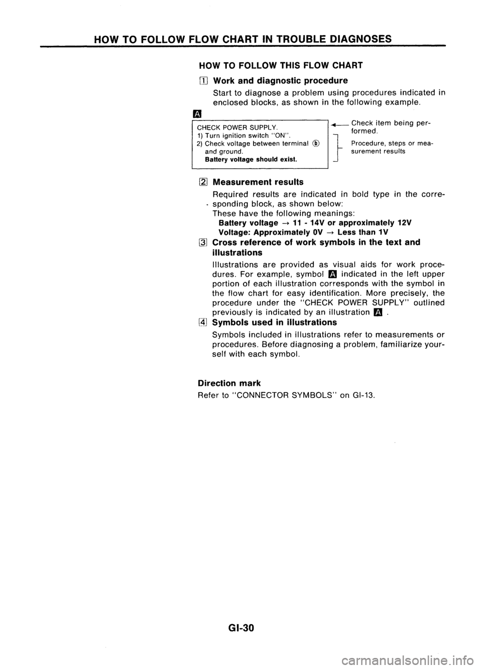
HOW TOFOllOW THISFLOW CHART
OJ
Work anddiagnostic procedure
Start todiagnose aproblem usingprocedures indicatedin
enclosed blocks,asshown inthe following example.
CHECK POWER SUPPLY.
1) Turn ignition switch"ON".
2) Check voltage between terminal
@
and ground.
Battery voltage shouldexist.
-+-
Check itembeing per-
formed.
} Procedure, stepsormea-
surement results
[2]
Measurement results
Required resultsareindicated inbold type inthe corre-
. sponding block,asshown below:
These havethefollowing meanings:
Battery voltage -11 .14V orapproximately 12V
Voltage: Approximately OV-Less than1V
~ Cross reference ofwork symbols inthe text and
illustrations
Illustrations areprovided asvisual aidsforwork proce-
dures. Forexample, symbol
m
indicated inthe leftupper
portion ofeach illustration corresponds withthesymbol in
the flow chart foreasy identification. Moreprecisely, the
procedure underthe"CHECK POWERSUPPLY" outlined
previously isindicated byan illustration
m.
[4J
Symbols usedinillustrations
Symbols includedinillustrations refertomeasurements or
procedures. Beforediagnosing aproblem, familiarize your-
self with each symbol.
Direction mark
Refer to"CONNECTOR SYMBOLS"onGI-13.
GI-30
Page 1399 of 1701
SAEJ1930 TERMINOLOGY LIST
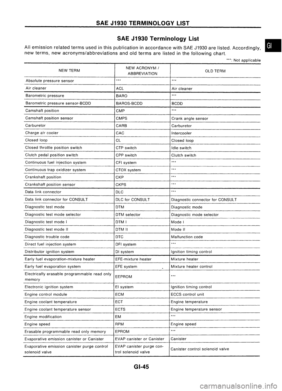
SAE J1930 Terminology List
All emission relatedtermsusedinthis publication inaccordance withSAE J1930 arelisted. Accordingly,
new terms, newacronyms/abbreviations andoldterms arelisted inthe following chart.
"':Not applicable
NEW TERM NEW
ACRONYM /
ABBREVIATION OLD
TERM
Absolute pressure sensor
'" '"
Air cleaner
ACLAircleaner
Barometric pressure
BARO
."
Barometric pressuresensor-BCDD
BAROS-BCDD BCDD
Camshaft position
CMP
'"
Camshaft positionsensor
CMPS Crankanglesensor
Carburetor CARBCarburetor
Charge aircooler
CACIntercooler
Closed loop
CLClosedloop
Closed throttle position switch
CTPswitch
Idleswitch
Clutch pedalposition switch
CPPswitch Clutchswitch
Continuous fuelinjection system
CFIsystem
'"
Continuous trapoxidizer system
CTOXsystem
...
Crankshaft position
CKP
'"
Crankshaft positionsensor
CKPS
~.**
Data linkconnector
DLC
,
..
Data linkconnector forCONSULT
DLCforCONSULT DiagnosticconnectorforCONSULT
Diagnostic testmode
DTMDiagnosticmode
Diagnostic testmode selector
DTMselector Diagnosticmodeselector
Diagnostic testmode I
DTMI ModeI
Diagnostic testmode II
DTMII ModeII
Diagnostic troublecode
DTC Malfunctioncode
Direct fuelinjection system
DFIsystem
..
,
Distributor ignitionsystem DIsystem Ignitiontimingcontrol
Early fuelevaporation-mixture heater
EFE-mixtureheater Mixture
heater
Early fuelevaporation system
EFEsystem
.
Mixture
heatercontrol
Electrically erasableprogrammable readonly
EEPROM
'"
memory
Electronic ignitionsystem EIsystem Ignitiontimingcontrol
Engine control module ECMECCScontrol unit
Engine coolant temperature ECTEngine
temperature
Engine coolant temperature sensor ECTS Engine
temperature sensor
Engine modification EM
'"
Engine speed RPM
Enginespeed
Erasable programmable readonlymemory EPROM
'"
Evaporative emissioncanisterorCanister EVAP
canister orCanister Canister
Evaporative emissioncanisterpurgecontrol EVAP
canister purgecon-
Canister controlsolenoid valve
solenoid valve trol
solenoid valve
GI-45
•
Page 1400 of 1701
SAEJ1930 TERMINOLOGY LIST
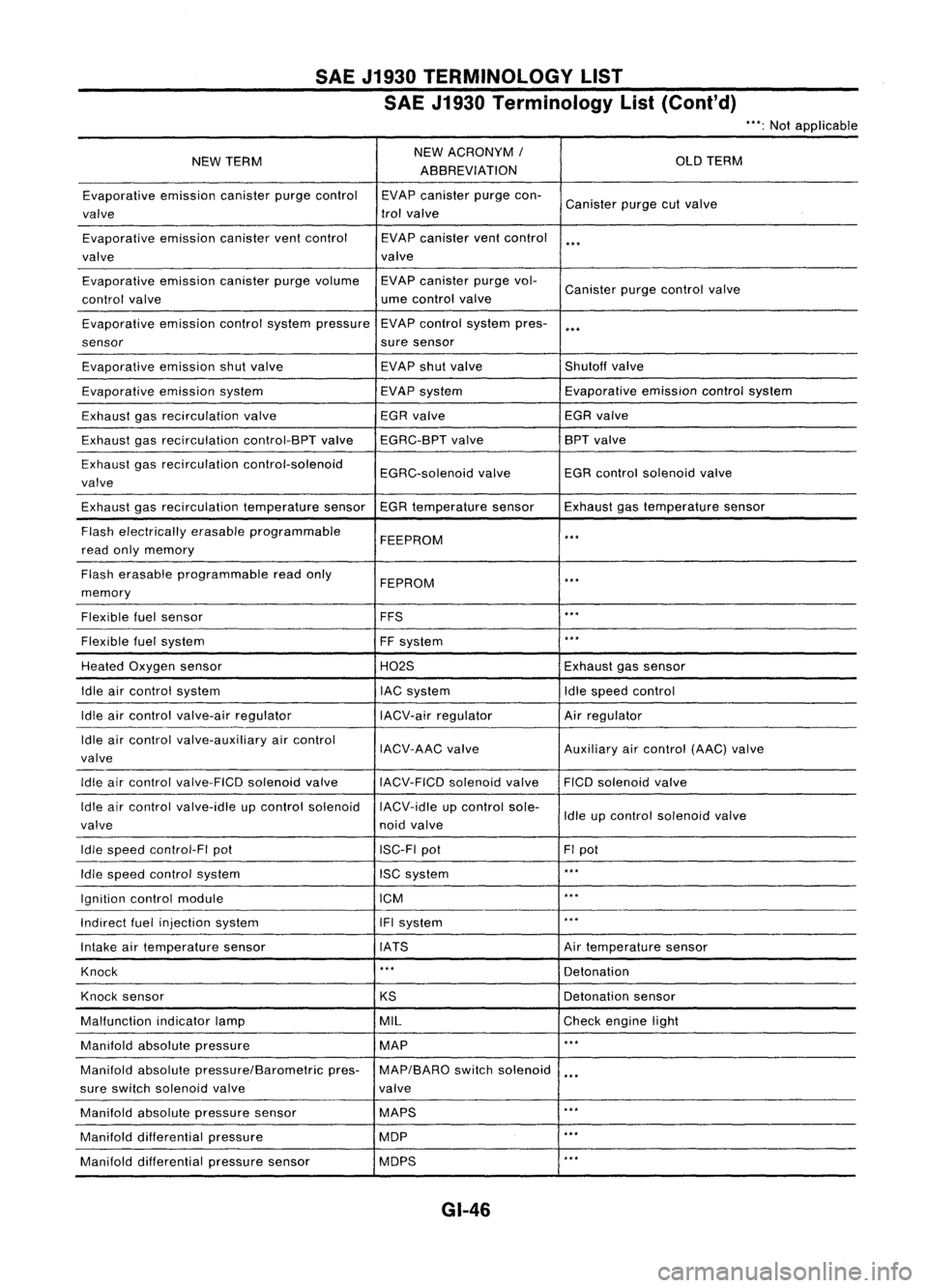
SAE J1930 Terminology List(Cont'd)
***:
Not applicable
NEW TERM NEW
ACRONYM /
OLDTERM
ABBREVIATION
Evaporative emissioncanisterpurgecontrol EVAPcanister purgecon-
Canister purgecutvalve
valve trol
valve
Evaporative emissioncanisterventcontrol EVAPcanister ventcontrol
***
valve valve
Evaporative emissioncanisterpurgevolume EVAPcanister purgevol-
Canister purgecontrol valve
control valve ume
control valve
Evaporative emissioncontrolsystem pressure EVAP
control system pres-
***
sensor suresensor
Evaporative emissionshutvalve EVAP
shutvalve Shutoffvalve
Evaporative emissionsystem EVAPsystem Evaporative
emissioncontrolsystem
Exhaust gasrecirculation valve EGR
valve EGRvalve
Exhaust gasrecirculation control-BPTvalveEGRC-BPT valve BPT
valve
Exhaust gasrecirculation control-solenoid
EGRC-solenoidvalveEGR
control solenoid valve
valve
Exhaust gasrecirculation temperaturesensorEGRtemperature sensorExhaustgastemperature sensor
Flash electrically erasableprogrammable
FEEPROM
***
read onlymemory
Flash erasable programmable readonly
FEPROM
**.
memory
Flexible fuelsensor FFS
***
Flexible fuelsystem
FFsystem
***
Heated Oxygen sensor H02SExhaustgassensor
Idle aircontrol system lACsystem Idlespeed control
Idle aircontrol valve-air regulator IACV-airregulator Airregulator
Idle aircontrol valve-auxiliary aircontrol
IACV-AACvalve Auxiliaryaircontrol (AAC)valve
valve
Idle aircontrol valve-FICO solenoidvalve
IACV-FICDsolenoidvalve FICOsolenoid valve
Idle aircontrol valve-idle upcontrol solenoid IACV-idleupcontrol sole-
Idleupcontrol solenoid valve
valve noidvalve
Idle speed control-FI pot ISC-FIpot FIpot
Idle speed control system ISCsystem
***
Ignition controlmodule ICM
***
Indirect fuelinjection system IFIsystem
***
Intake airtemperature sensor IATS Airtemperature sensor
Knock
***
Detonation
Knock sensor
KSDetonation
sensor
Malfunction indicatorlamp MIL
Checkengine light
Manifold absolutepressure MAP
***
Manifold absolutepressure/Barometric pres-MAP/BARO switchsolenoid
***
sure switch solenoid valve valve
Manifold absolutepressure sensor MAPS
**.
Manifold differential pressure MOP
***
Manifold differential pressuresensor MOPS
***
GI-46