1995 NISSAN ALMERA N15 ESP
[x] Cancel search: ESPPage 1402 of 1701
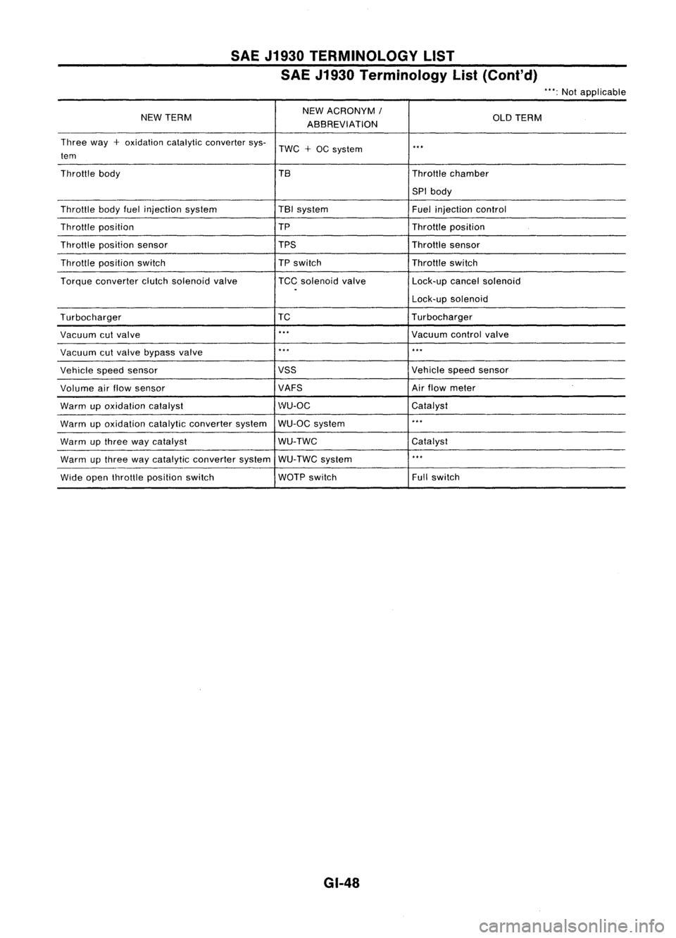
SAEJ1930 TERMINOLOGY LIST
SAE J1930 Terminology List(Cont'd)
"':Not applicable
NEW TERM NEW
ACRONYM
I
OLDTERM
ABBREVIATION
Three way
+
oxidation catalyticconverter sys-
TWC
+
OC system
..
,
tem
Throttle body TBThrottlechamber
SPI body
Throttle bodyfuelinjection system TBI
system
Fuelinjection control
Throttle position TP
Throttleposition
Throttle position sensor TPSThrottlesensor
Throttle position switch
TP
switch Throttleswitch
Torque converter clutchsolenoid valve TCCsolenoid valve Lock-upcancelsolenoid
.
Lock-upsolenoid
Turbocharger TC
Turbocharger
Vacuum cutvalve
..
,
Vacuumcontrolvalve
Vacuum cutvalve bypass valve
..
,
...
Vehicle speedsensor VSS
Vehiclespeedsensor
Volume airflow sensor VAFSAir
flow meter
Warm upoxidation catalyst WU-OC
Catalyst
Warm upoxidation catalyticconverter systemWU-OC
system
..
,
Warm upthree waycatalyst WU-TWC
Catalyst
Warm upthree waycatalytic converter systemWU-TWC system
..
,
Wide open throttle position switch WOTP
switch Fullswitch
GI-48
Page 1405 of 1701
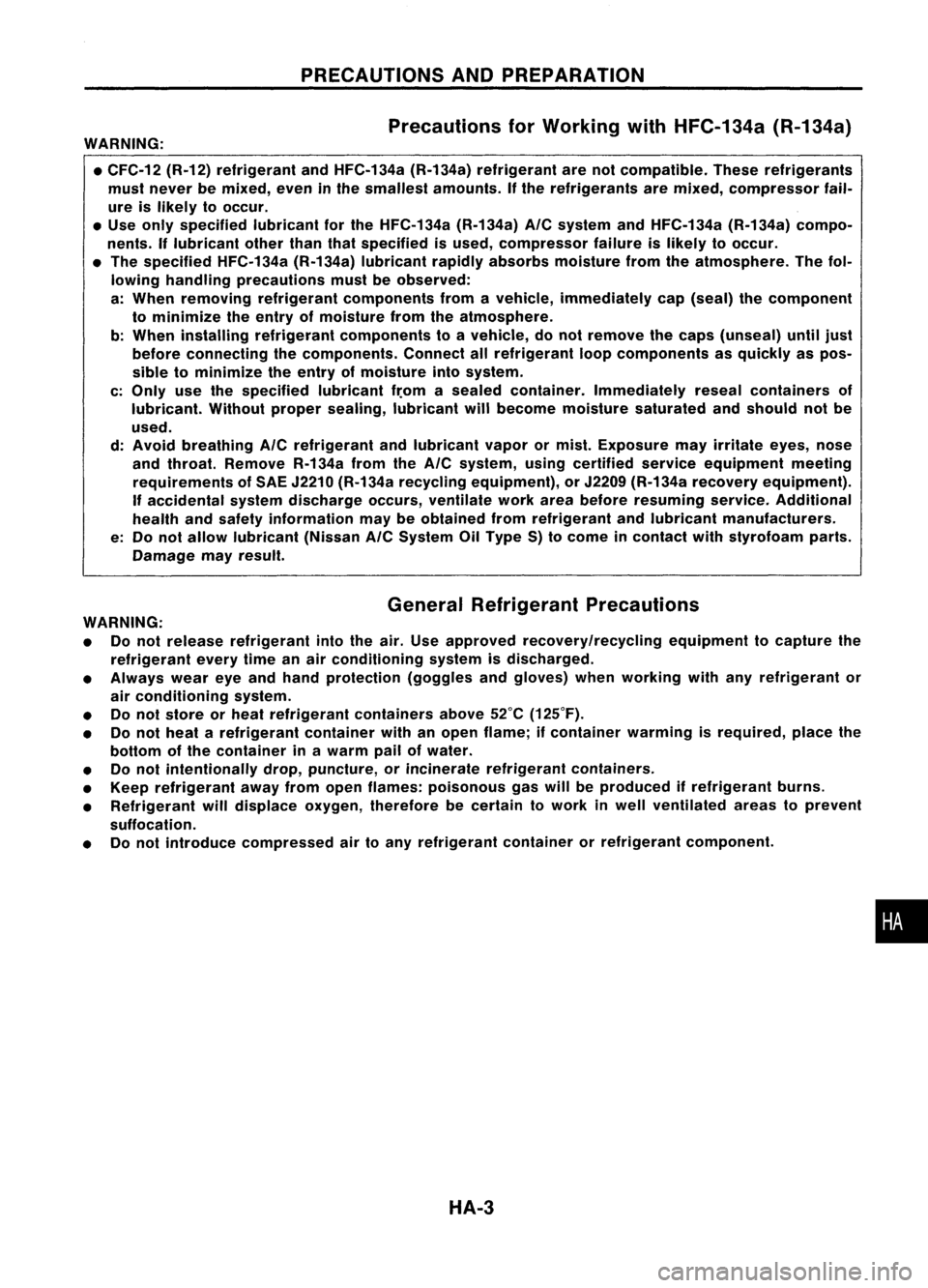
PRECAUTIONSANDPREPARATION
Precautions forWorking withHFC-134a (R-134a)
WARNING:
• CFC-12 (R-12)refrigerant andHFC-134a (R-134a)refrigerant arenotcompatible. Theserefrigerants
must never bemixed, eveninthe smallest amounts. Ifthe refrigerants aremixed, compressor fail-
ure islikely tooccur .
• Use only specified lubricantforthe HFC-134a (R-134a)
A/C
system andHFC-134a (R-134a)compo-
nents. Iflubricant otherthanthatspecified isused, compressor failureislikely tooccur .
• The specified HFC-134a (R-134a)lubricant rapidlyabsorbs moisture fromtheatmosphere. Thefol-
lowing handling precautions mustbeobserved:
a: When removing refrigerant components fromavehicle, immediately cap(seal) thecomponent
to minimize theentry ofmoisture fromtheatmosphere.
b: When installing refrigerant components toavehicle, donot remove thecaps (unseal) untiljust
before connecting thecomponents. Connectallrefrigerant loopcomponents asquickly aspos-
sible tominimize theentry ofmoisture intosystem.
c: Only usethespecified lubricantfr.omasealed container. Immediately resealcontainers of
lubricant. Withoutpropersealing, lubricant willbecome moisture saturated andshould notbe
used.
d: Avoid breathing
A/C
refrigerant andlubricant vaporormist. Exposure mayirritate eyes,nose
and throat. Remove R-134afromthe
A/C
system, usingcertified serviceequipment meeting
requirements ofSAE J2210 (R-134a recycling eqUipment), orJ2209 (R-134a recovery equipment).
If accidental systemdischarge occurs,ventilate workareabefore resuming service.Additional
health andsafety information maybeobtained fromrefrigerant andlubricant manufacturers.
e: Do not allow lubricant (Nissan
A/C
System OilType S)tocome incontact withstyrofoam parts.
Damage mayresult.
GeneralRefrigerant Precautions
WARNING:
• Donot release refrigerant intotheair. Use approved recoverylrecycling equipmenttocapture the
refrigerant everytimeanair conditioning systemisdischarged.
• Always weareyeand hand protection (gogglesandgloves) whenworking withanyrefrigerant or
air conditioning system.
• Donot store orheat refrigerant containersabove52°C(125°F).
• Donot heat arefrigerant containerwithanopen flame; ifcontainer warmingisrequired, placethe
bottom ofthe container inawarm pailofwater.
• Donot intentionally drop,puncture, orincinerate refrigerant containers.
• Keep refrigerant awayfromopen flames: poisonous gaswillbeproduced ifrefrigerant burns.
• Refrigerant willdisplace oxygen,therefore becertain towork inwell ventilated areastoprevent
suffocation.
• Donot introduce compressed airtoany refrigerant containerorrefrigerant component.
HA-3
•
Page 1410 of 1701
PRECAUTIONSANDPREPARATION
Precautions forService Equipment
RECOVERY/RECYCLING/RECHARGING EQUIPMENT
Be certain tofollow themanufacturers instructionsformachine
operation andmachine maintenance. Neverintroduce any
refrigerant otherthanthatspecified intothemachine.
ELECTRONIC LEAKDETECTOR
Be certain tofollow themanufactures instructionsfortester
operation andtester maintenance.
With isolator valve
Without isolatorvalve
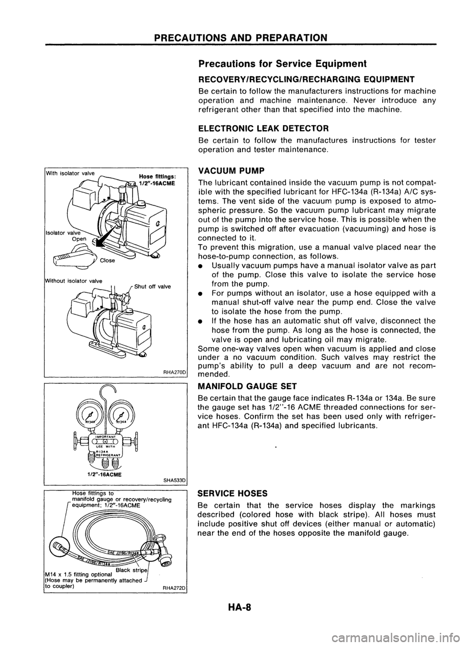
VACUUM
PUMP
Hose fittings:
1/2".16ACME
Thelubricant contained insidethevacuum pumpisnot compat-
ible with thespecified lubricantforHFC-134a (R-134a)
AIC
sys-
tems. Thevent sideofthe vacuum pumpisexposed toatmo-
spheric pressure. Sothe vacuum pumplubricant maymigrate
out ofthe pump intotheservice hose.Thisispossible whenthe
pump isswitched offafter evacuation (vacuuming) andhose is
connected toit.
To prevent thismigration, useamanual valveplaced nearthe
hose-to-pump connection,asfollows.
• Usually vacuum pumpshaveamanual isolatorvalveaspart
of the pump. Closethisvalve toisolate theservice hose
from thepump.
• For pumps without anisolator, useahose equipped witha
manual shut-off valvenearthepump end.Close thevalve
to isolate thehose fromthepump.
• Ifthe hose hasanautomatic shutoffvalve, disconnect the
hose fromthepump. Aslong asthe hose isconnected, the
valve isopen andlubricating oilmay migrate.
Some one-way valvesopenwhen vacuum isapplied andclose
under ano vacuum condition. Suchvalves mayrestrict the
pump's abilitytopull adeep vacuum andarenotrecom-
RHA270D
mended.
MANIFOLD GAUGESET
Be certain thatthegauge faceindicates R-134aor134a. Besure
the gauge sethas
1/2"-16
ACMEthreaded connections forser-
vice hoses. Confirm theset has been usedonlywith refriger-
ant HFC-134a (R-134a)andspecified lubricants.
~
1f2"-16ACME
SHA533D
Hose fittings to
manifold gaugeorrecovery/recycling
equipment; 1/2"-16ACME
RHA272DSERVICE
HOSES
Be certain thattheservice hosesdisplay themarkings
described (coloredhosewithblack stripe). Allhoses must
include positive shutoffdevices (eithermanual orautomatic)
near theend ofthe hoses opposite themanifold gauge.
HA-8
Page 1412 of 1701
DESCRIPTION
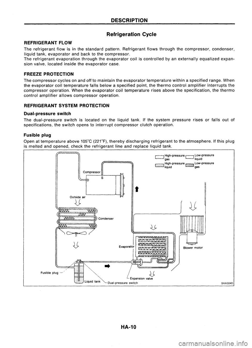
Refrigeration Cycle
REFRIGERANT FLOW
The refrigerant flowisinthe standard pattern.Refrigerant flowsthrough thecompressor, condenser,
liquid tank,evaporator andback tothe compressor.
The refrigerant evaporation throughtheevaporator coiliscontrolled byan externally equalizedexpan-
sion valve, located insidetheevaporator case.
FREEZE PROTECTION
The compressor cyclesonand offtomaintain theevaporator temperature withinaspecified range.When
the evaporator coiltemperature fallsbelow aspecified point,thethermo controlamplifier interrupts the
compressor operation.Whentheevaporator coiltemperature risesabove thespecification, thethermo
control amplifier allowscompressor operation.
REFRIGERANT SYSTEMPROTECTION
Dual-pressure switch
The dual-pressure switchislocated onthe liquid tank.Ifthe system pressure risesorfalls outof
specifications, theswitch openstointerrupt compressor clutchoperation.
Fusible plug
Open attemperature above105°C(221°F), thereby discharging refrigeranttothe atmosphere. Ifthis plug
is melted andopened, checktherefrigerant lineand replace liquidtank.
c:::::.J
High-pressure
EJ
Low-pressure
gas liquid
1:-:-:-:-::-:-::-:-:1
~~~~pressure
!::i'i'i':}':J
~~:-pressure
Compressor
D
Outside air
U
s
t
Fusible plug-~
~..
U
'" Expansionvalve
Liquid tank"'--Dual-pressure switch
HA-10
Blower
motor
SHA504D
Page 1426 of 1701
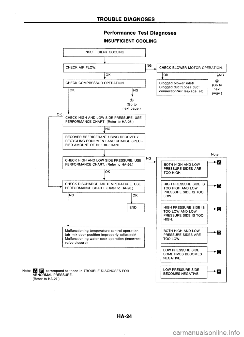
TROUBLEDIAGNOSES
Performance TestDiagnoses
INSUFFICIENT COOLING
INSUFFICIENT COOLING
CHECK AIRFLOW.
OK CHECK
BLOWER MOTOROPERATION.
OK
CHECK COMPRESSOR OPERATION.
OK Clogged
blowerinlet!
Clogged duct/Loose duct
connection/Air leakage,etc.
@
(Go to
next
page.)
(Go to
next page.)
OK CHECK HIGHANDLOW SIDE PRESSURE. USE
PERFORMANCE CHART.(RefertoHA-26.)
NG
RECOVER REFRIGERANT USINGRECOVERY
RECYCLING EQUIPMENT ANDCHARGE SPECI-
FIED AMOUNT OFREFRIGERANT.
CHECK HIGHANDLOW SIDE PRESSURE. USE
PERFORMANCE CHART.(RefertoHA-26.)
OK
CHECK DISCHARGE AIRTEMPERATURE. USE
PERFORMANCE CHART.(RefertoHA-26.)
NG
Malfunctioning temperaturecontroloperation
(air mix door position improperly adjusted)/
Malfunctioning watercockoperation (incorrect
valve closure)
Note:
Fa-Ii
correspond tothose inTROUBLE DIAGNOSES FOR
ABNORMAL PRESSURE.
(Refer toHA-27.)
HA-24NG
Note
BOTH HIGHANDLOW
m
PRESSURE SIDESARE
TOO HIGH.
HIGH PRESSURE SIDEIS
(;]
TOO HIGH ANDLOW
PRESSURE SIDEISTOO
LOW.
HIGH PRESSURE SIDEIS
TOO LOW ANDLOW
PRESSURE SIDEISTOO
HIGH.
BOTH HIGHANDLOW
Ii]
PRESSURE SIDESARE
TOO LOW.
LOW PRESSURE SIDE
SOMETIMES BECOMES
NEGATIVE.
LOW PRESSURE SIDE
Ii
BECOMES NEGATIVE.
Page 1428 of 1701
TROUBLEDIAGNOSES
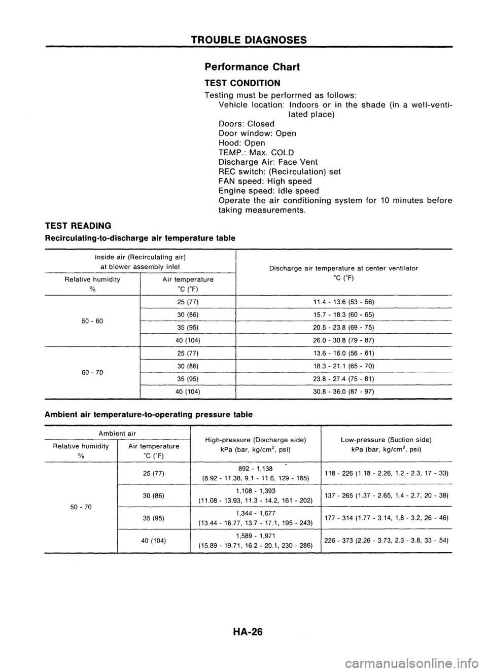
Performance Chart
TEST CONDITION
Testing mustbeperformed asfollows:
Vehicle location: Indoorsorinthe shade (inawell-venti-
lated place)
Doors: Closed
Door window: Open
Hood: Open
TEMP.: Max.COLD
Discharge Air:Face Vent
REC switch: (Recirculation) set
FAN speed: Highspeed
Engine speed:Idlespeed
Operate theairconditioning systemfor10minutes before
taking measurements.
TEST READING
Recirculating-to-discharge airtemperature table
Inside air(Recirculating air)
at blower assembly inlet
Dischargeairtemperature atcenter ventilator
Relative humidity
Airtemperature .C
('F)
%
.C
('F)
25 (77) 11.4
-13.6 (53-56)
30 (86) 15.7-18.3 (60-65)
50 -60
35(95) 20.5-23.8 (69-75)
40 (104) 26.0-30.8 (79-87)
25 (77) 13.6-16.0 (56-61)
30 (86) 18.3-21.1 (65-70)
60 -70
35(95) 23.8-27.4 (75-81)
40 (104) 30.8-36.0 (87-97)
Ambient airtemperature-to-operating pressuretable
Ambient air
High-pressure(Dischargeside) Low-pressure
(Suctionside)
Relative humidity Airtemperature
kPa(bar,
kg/cm
2,
psi) kPa
(bar,
kg/cm
2,
psi)
%
.C
('F)
.
25 (77) 892
-1,138
118-226 (1.18 -2.26,1.2 -2.3,17 -33)
(8.92 -11.38, 9.1-11.6,129 -165)
30 (86) 1,108
-1,393
137-265 (1.37 -2.65,1.4 -2.7,20 -38)
(11.08 -13.93, 11.3-14.2, 161-202)
50 -70
35(95) 1,344
-1,677
177-314 (1.77 -3.14,1.8 -3.2, 26-46)
(1344 -16.77,13.7 -17.1, 195-243)
40 (104) 1,589
-1,971
226-373 (2.26 -3.73, 2.3-3.8, 33-54)
(15.89 -19.71,16.2 -20.1, 230-286)
HA-26
Page 1431 of 1701
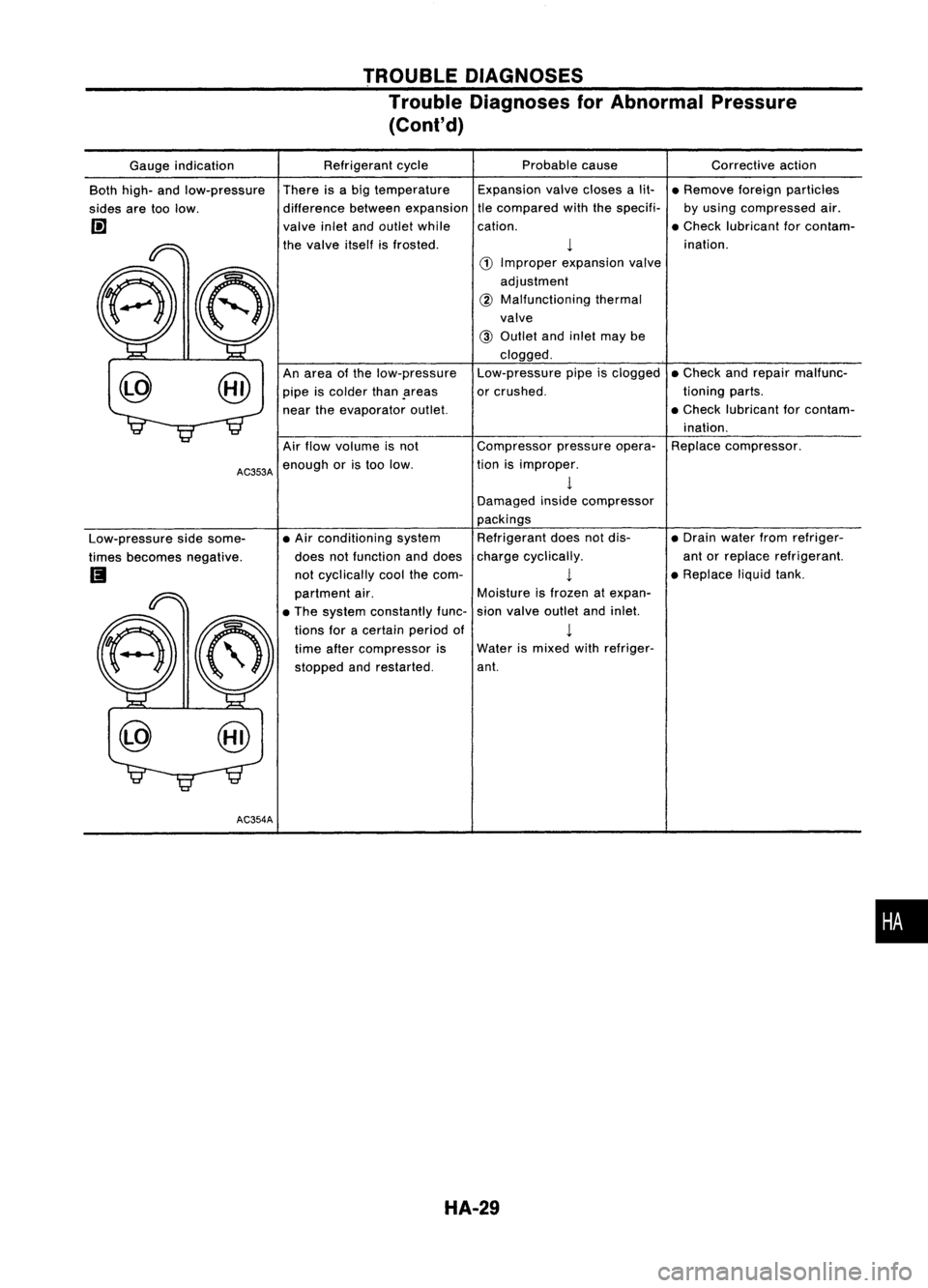
TROUBLEDIAGNOSES
Trouble Diagnoses forAbnormal Pressure
(Cont'd)
Correctiveaction
• Remove foreignparticles
by using compressed air.
• Check lubricant forcontam-
ination.
• Check andrepair malfunc-
tioning parts.
• Check lubricant forcontam-
ination.
Replace compressor.
• Drain water fromrefriger-
ant orreplace refrigerant.
• Replace liqUidtank.
Expansion
valvecloses alit-
tle compared withthespecifi-
cation.
1
Water ismixed withrefriger-
ant. Probable
cause
1
CD
Improper expansion valve
adjustment
@
Malfunctioning thermal
valve
@
Outlet andinlet maybe
clogged.
Low-pressure pipeisclogged
or crushed.
Compressor pressureopera-
tion isimproper.
1
Damaged insidecompressor
packings Refrigerant doesnotdis-
charge cyclically.
1
Moisture isfrozen atexpan-
sion valve outlet andinlet.
Refrigerant
cycle
There isabig temperature
difference betweenexpansion
valve inletandoutlet while
the valve itselfisfrosted.
An area ofthe low-pressure
pipe iscolder thanpreas
near theevaporator outlet.
• Air conditioning system
does notfunction anddoes
not cyclically coolthecom-
partment air.
• The system constantly func-
tions foracertain periodof
time after compressor is
stopped andrestarted.
Air
flow volume isnot
AC353A
enough oristoo low.
@ Gauge
indication
Both high- andlow-pressure
sides aretoolow.
l!]
Low-pressure sidesome-
times becomes negative.
Ii
AC354A
•
HA-29
Page 1470 of 1701
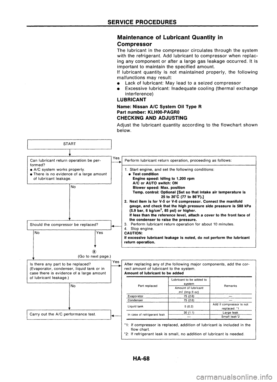
SERVICEPROCEDURES
Maintenance ofLubricant Quantityin
Compressor
The lubricant inthe compressor circulatesthroughthesystem
with therefrigerant. Addlubricant tocompressor whenreplac-
ing any component orafter alarge gasleakage occurred. Itis
important tomaintain thespecified amount.
If lubricant quantityisnot maintained properly,thefollowing
malfunctions mayresult:
• Lack oflubricant: Maylead toaseized compressor
• Excessive lubricant:Inadequate cooling(thermal exchange
interference)
LUBRICANT
Name: Nissan
Ale
System OilType R
Part number:
KLHOO-PAGRO
CHECKING ANDADJUSTING
Adjust thelubricant quantityaccording tothe flowchart shown
below.
START
~
Can lubricant returnoperation beper- Yes
Perform lubricant returnoperation, proceeding asfollows:
formed?
-+
• AIC
system worksproperly. 1.Start engine, andsetthefollowing conditions:
• There isno evidence ofalarge amount •Test condition
of lubricant leakage. Engine
speed:Idlingto1,200 rpm
AlC orAUTO switch: ON
No Blowerspeed:Max.position
Temp. control: Optional [Setsothat Intake airtemperature is
25 to30°C (77to86°F).]
2. Next itemisfor V-5 orV-6 compressor. Connectthemanifold
gauge, andcheck thatthehigh pressure sidepressure is588 kPa
(5.9 bar, 6kg/cm
2,
85psi) orhigher,
If
less than thereference level,attach acover tothe front faceof
~
the
condenser toraise thepressure.
Should thecompressor bereplaced?
3.
Perform lubricant returnoperation forabout 10minutes.
4.
Stop engine.
No Yes
CAUTION:
If
excessive lubricantleakageisnoted, donot perform thelubricant
return operation.
@
(Go tonext page.)
Is there anypart tobe replaced? Yes
Afterreplacing anyof.the following majorcomponents, addthecor-
(Evaporator, condenser,liquidtankorin
-..
rectamount oflubricant tothe system.
case there isevidence ofalarge amount Amountoflubricant tobe added
of lubricant leakage.)
Lubricanttobe added to
No
Part
replaced system
Remarks
Amount oflubricant
mf (Imp IIoz)
Evaporator 75(2.6)
-
Condenser 75(2.6)
-
Liquid tank 5(0.2) Add
ifcompressor isnot
replaced. '1
Carry outthe
AIC
performance test.
~
In
case ofrefrigerant leak 30
(11) Largeleak
-
Small
leak'2
.
*1:Ifcompressor isreplaced. additionoflubricant isincluded inthe
flow chart.
*2: Ifrefrigerant leakissmall, noaddition oflubricant isneeded.
HA-68