Page 1487 of 1701
SECTION
CONTENTS
MAINTENANCE
MA
•
PRECAUTIONS ANDPREPARATION
3
Supplemental RestraintSystem(SRS)"AIR
BAG" (DualAirBag System) 3
Supplemental RestraintSystem(SRS)"AIR
BAG" (Single AirBag System) 3
Special Service Tools 4
Commercial ServiceTool 4
PRE-DELIVERY INSPECTIONITEMS
5
GENERAL MAINTENANCE 6
PERIODIC MAINTENANCE (Exceptfor
Europe) 7
Engine andEmission ControlService 7
Chassis andBody Service 8
Maintenance UnderSevere DrivingConditions 9
PERIODIC MAINTENANCE (ForEurope) 10
Engine Oil
&
Minor Service 10
Engine andEmission ControlService 11
Chassis andBody Services 12
Maintenance UnderSevere Driving Conditions 13
RECOMMENDED LUBRICANTSANDFLUIDS 14
Lubricants andFluids 14
SAE Viscosity Number 15
Anti-freeze CoolantMixtureRatio 16
~ --ll
GA
I I
ENGINE MAINTENANCE 17
Checking DriveBelts 17
Changing EngineCoolant... 19
Checking CoolingSystem 21
Checking FuelLines 22
Changing FuelFilter 22
Cleaning andChanging AirCleaner Filter 23
Changing EngineOil 24
Changing OilFilter 24
Checking andChanging SparkPlugs 25
Checking IgnitionWires 26Changing
PositiveCrankcase Ventilation
(PCV) Filter 26
Checking EVAPVapor Lines 26
Checking OxygenSensor(02S)orHeated
Oxygen Sensor(H02S) 27
~ --ll
SR
I I
ENGINE MAINTENANCE 28
Checking DriveBelts 28
Changing EngineCoolant... 29
Checking CoolingSystem 31
Checking FuelLines 32
Changing FuelFilter 32
Changing AirCleaner Filter 33
Changing EngineOil 33
Changing OilFilter 34
Changing SparkPlugs(Platinum-tipped type)34
Checking IgnitionWires 35
Checking EVAPVapor
&
Purge Lines 36
Checking HeatedOxygen Sensor(H02S) 37
~_~ ..-JI
CD
I I
ENGINE MAINTENANCE
38
Manifold NutCheck 38
Checking DriveBelt 38
Changing EngineCoolant. 38
Checking CoolingSystem .40
Checking FuelLine .40
Changing AirCleaner Filter 41
Water Draining, FuelFilter Check and
Replacement 41
Changing EngineOil .41
Changing EngineOilFilter 42
Checking InjectionNozzle 43
Checking IdleSpeed .44
Replacing TimingBelt 44
Page 1508 of 1701
ENGINEMAINTENANCE ~
Checking CoolingSystem(Cont'd)
Pull thenegative-pressure valvetoopen it.Check thatitcloses
completely whenreleased.
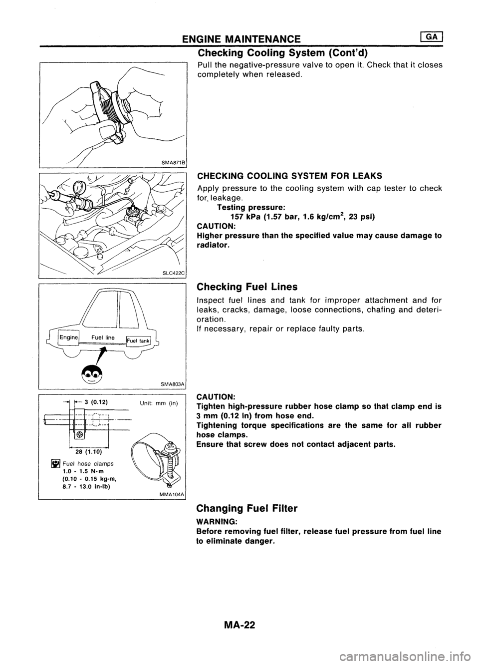
SMA871B CHECKING COOLINGSYSTEMFORLEAKS
Apply pressure tothe cooling systemwithcaptester tocheck
for. leakage.
Testing pressure:
157 kPa (1.57 bar,1.6kg/cm
2,
23psi)
CAUTION: Higher pressure thanthespecified valuemaycause damage to
radiator.
Checking Fuellines
Inspect fuellines andtank forimproper attachment andfor
leaks, cracks, damage, looseconnections, chafinganddeteri-
oration. If necessary, repairorreplace faultyparts.
SMA803A
3 (0.12) Unit:mm(in)
-- --- ----,;~-r--1
"
,
-,-,-,
~-
_______ .J",_~__
28 (1.10)
~ Fuel hose clamps
1.0 -1.5 N.m
(0.10 -0.15 kg-m,
8.7 -13.0 in-Ib)
MMA104ACAUTION:
Tighten high-pressure rubberhoseclamp sothat clamp endis
3 mm (0.12 in)from hose end.
Tightening torquespecifications arethesame forallrubber
hose clamps.
Ensure thatscrew doesnotcontact adjacent parts.
Changing FuelFilter
WARNING: Before removing fuelfilter, release fuelpressure fromfuelline
to eliminate danger.
MA-22
Page 1518 of 1701
![NISSAN ALMERA N15 1995 Service Manual ENGINEMAINTENANCE [][]
Checking CoolingSystem(Cont'd)
Pull thenegative-pressure valvetoopen it.Check thatitcloses
completely whenreleased.
CHECKING COOLINGSYSTEMFORLEAKS
Apply pressure tothe c NISSAN ALMERA N15 1995 Service Manual ENGINEMAINTENANCE [][]
Checking CoolingSystem(Cont'd)
Pull thenegative-pressure valvetoopen it.Check thatitcloses
completely whenreleased.
CHECKING COOLINGSYSTEMFORLEAKS
Apply pressure tothe c](/manual-img/5/57349/w960_57349-1517.png)
ENGINEMAINTENANCE [][]
Checking CoolingSystem(Cont'd)
Pull thenegative-pressure valvetoopen it.Check thatitcloses
completely whenreleased.
CHECKING COOLINGSYSTEMFORLEAKS
Apply pressure tothe cooling systemwithcaptester tocheck
f~r leakage.
Testing pressure:
157 kPa (1.57 bar,1.6kg/cm
2,
23psi)
CAUTION:
Higher pressure thanthespecified valuemaycause damage to
radiator.
SMA811C
SMA803A
Checking
FuelLines
Inspect fuellines andtank forimproper attachment, leaks,
cracks, damage, looseconnections, chafingordeterioration.
If necessary, repairorreplace faultyparts.
3 (0.12) Unit:mm(in)
_._-- --,"'~'r---1
"
,
-
-
---;--,
-,---
•• J..
_J- __
28 (1.10)
~ Fuel hose clamps
1.0 -1.5 N.m
(0.10 -0.15 kg-m,
8.7 -13.0 in-Ib)
MMA104A
• FUEL PRESRELEASE.
0
FUEL PUMP WILLSTOP BY
TOUCHING STARTDURING
IDLE_
CRANK AFEW TIMES AFTER
ENGINE STALL.
---S-T~-RT--
SEF823KCAUTION:
Tighten high-pressure rubberhoseclamp sothat clamp endis
3 mm (0.12 in)from hose end.
Tightening torquespecifications arethesame forallrubber
hose clamps.
Ensure thatscrew doesnotcontact adjacent parts.
Changing FuelFilter
WARNING:
Before removing fuelfilter, release fuelpressure fromfuelline
to eliminate danger.
rF.i\
1.Start engine.
~ 2.Perform "FUELPRESSURE RELEASE"in"WORK
SUPPORT" modewithCONSULT.
3. After engine stalls,crankengine twoorthree times
to make surethatfuel pressure isreleased.
4. Turn ignition switchoff.
MA-32
Page 1526 of 1701
ENGINEMAINTENANCE
Checking CoolingSystem
HOSE ANDCLAMP CHECK
Check hosesforimproper attachment, leaks,cracks, damage,
loose connections, chafinganddeterioration.
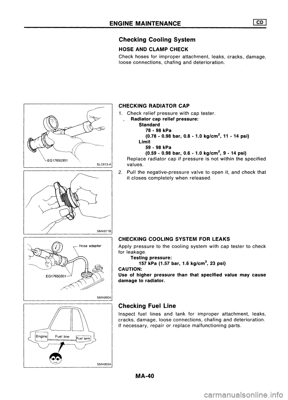
CHECKING COOLINGSYSTEMFORLEAKS
Apply pressure tothe cooling systemwithcaptester tocheck
for leakage.
Testing pressure:
157
kPa
(1.57
bar,
1.6
kg/cm
2,
23psi)
CAUTION: Use ofhigher pressure thanthatspecified valuemaycause
damage toradiator.
CHECKING
RADIATORCAP
1. Check reliefpressure withcaptester.
Radiator caprelief pressure:
Standard
78.98
kPa
(0.78.0.98
bar,
0.8-1.0
kg/cm
2,
11-14
psi)
Limit
59 -98
kPa
(0.59 -0.98
bar,
0.6-1.0
kg/cm
2,
9-14
psi)
Replace radiatorcapifpressure isnot within thespecified
SLC613-A
values.
2. Pull thenegative-pressure valvetoopen it,and check that
it closes completely whenreleased.
Hose adapter
SMA990A
SMA803A Checking
FuelLine
Inspect fuellines andtank forimproper attachment, leaks,
cracks, damage, looseconnections, chafinganddeterioration.
If necessary, repairorreplace malfunctioning parts.
MA-40
Page 1530 of 1701
ENGINEMAINTENANCE
Checking InjectionNozzle(Cont'd)
Nozzle side
Combustion
chamber side
SEF668A Checking IdleSpeed
PREPARATION
1: Make surethatinjection timingiscorrect.
2. Make surethatinjection nozzlesareingood condition.
3. Make surethatthefollowing partsareingood condition.
• Air cleaner clogging
• Glow system
• Engine oiland coolant levels
• Air intake system (Oilfiller cap,oillevel gauge, etc.)
4. Set shift lever in"Neutral" position.Engageparkingbrake
and lock both front andrear wheels withwheel chocks.
5. Turn offair conditioner, lightsandaccessories.
6. Warm upengine tonormal operating temperature.
7. Attach adiesel tachotester.
8. Race engine twoorthree times andcheck idlespeed.
Idle speed (M/T):
700~go rprn
9.
If
itis out ofspecification, adjustidlespeed withidlespeed
adjusting screw.
Securely locktheadjusting screwwithlock nut.
Idle speed
adjusting screw
Fuel injection pump
SMA420C
Replacing TimingBelt
Refer to"TIMING BELT"inEM section.
MA-44
Page 1584 of 1701
REPAIRFORCOMPONENT PARTS
I
RS5F32A
I
Snap ring End
play
Mainshaft
andGears
DISASSEMBL Y
1. Before disassembly, measuregearendplay.
Gear endplay:
Refer to50S, MT-64.
• Ifend play isnot within thespecified limit,disassemble and
check theparts.
2. Remove mainshaft rearbearing snapring,Coring holder
and mainshaft C-rings.
C-ring holder
SMT709B
~Snapring
@---
C-ringholder
~~ MalnshaftC-r1ng
Puller-
Mainshaft rear
bearing -
Mainshaft rear
bearing
SMT676BB
3.Remove mainshaft rearbearing andspacer.
./- Suitable
drift
SMT677BA
4.Remove 5thmain gear.
SMT593-A MT-42
Page 1607 of 1701
SERVICEDATAANDSPECIFICATIONS (SDS)
Inspection andAdjustment -RS5F32A (Cont'd)
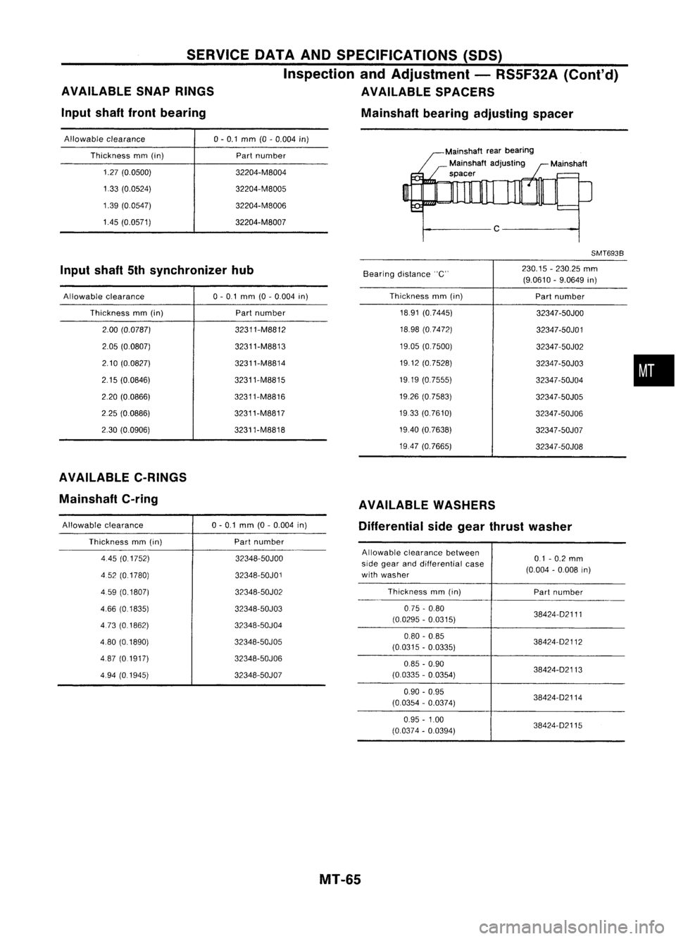
AVAILABLE SNAPRINGS AVAILABLESPACERS
Input shaftfrontbearing Mainshaftbearingadjusting spacer
Allowable clearance 0-0.1 mm (0-0.004 in)
Thickness mm(in)
1.27 (0.0500)
133 (0.0524)
1.39 (0.0547)
1.45 (0.0571) Part
number
32204-M8004
32204-M8005
32204-M8006
32204-M8007 Mainshaft
rearbearing
Mainshaft adjusting
spacer
c
SMT6938
Input shaft5thsynchronizer hub
Bearingdistance "C" 230.15
-230.25 mm
(9.0610 -9.0649 in)
Allowable clearance
Thickness mm(in)
2.00 (0.0787)
2.05 (0.0807)
2.10 (0.0827)
2.15 (0.0846)
2.20 (0.0866)
225 (0.0886)
2.30 (0.0906) 0-
0.1 mm (0-0.004 in)
Part number
32311-M8812
32311-M8813
32311-M8814
32311-M8815
32311-M8816
32311-M8817
32311-M8818 Thickness
mm(in)
1891 (0.7445)
18.98 (0.7472)
19.05 (0.7500)
1912 (0.7528)
1919 (0.7555)
19.26 (0.7583)
1933 (0.7610)
19.40 (0.7638)
19.47 (0.7665) Part
number
32347 -50JOO
32347-50J01
32347-50J02
32347 -50J03
32347 -50J04
32347 -50J05
32347 -50J06
32347-50J07
32347 -50J08
•
AVAILABLE C-RINGS
Mainshaft C-ring
Allowable clearance
Thickness mm(in)
4.45 (0.1752)
4.52 (01780)
4 59 (0.1807)
4.66 (01835)
473 (0.1862)
480 (0.1890)
487 (0.1917)
4.94 (0.1945) 0-
0.1 mm (0-0.004 in)
Part number
32348-50JOO
32348-50J01
32348-50J02
32348-50J03
32348-50J04
32348-50J05
32348-50J06
32348-50J07 AVAILABLE
WASHERS
Differential sidegear thrust washer
Allowable clearance between
01-0.2 mm
side gear anddifferential case
(0.004-0.008 in)
with washer
Thickness mm(in)
Partnumber
075 -0.80
(0.0295 -0.0315) 38424-02111
0.80 -085
38424-02112
(0.0315 -0.0335)
0.85 -0.90
38424-02113
(0.0335 -0.0354)
0.90 -0.95
38424-02114
(00354 -0.0374)
0.95 -1.00
(0.0374 -0.0394) 38424-02115
MT-65
Page 1637 of 1701
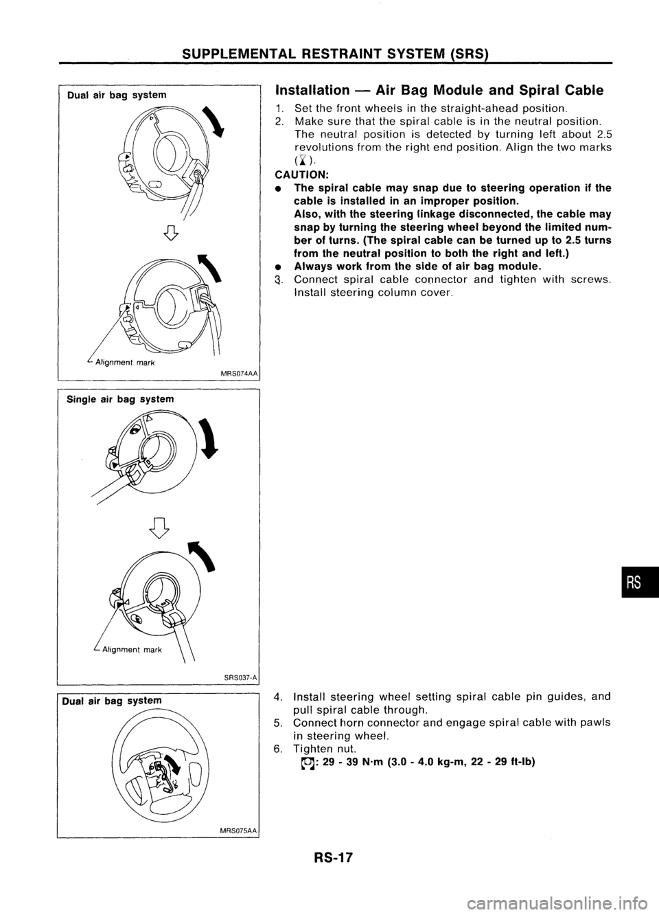
SUPPLEMENTALRESTRAINTSYSTEM(SRS)
Dual airbag system Installation
-Air Bag Module andSpiral Cable
1. Set thefront wheels inthe straight-ahead position.
2. Make surethatthespiral cableisin the neutral position.
The neutral position isdetected byturning leftabout 2.5
revolutions fromtheright endposition. Alignthetwo marks
(~ ).
CAUTION:
• The spiral cablemaysnap duetosteering operation ifthe
cable isinstalled inan improper position.
Also, withthesteering linkagedisconnected, thecable may
snap byturning thesteering wheelbeyond thelimited num-
ber ofturns. (Thespiral cablecanbeturned upto2.5 turns
from theneutral position toboth theright andleft.)
• Always workfromtheside ofair bag module.
3.
Connect spiralcablecOnnector andtighten withscrews.
Install steering columncover.
Single airbag system
Dual airbag system MRS074AA
SRS037-A
4.Install steering wheelsetting spiralcablepinguides, and
pull spiral cablethrough.
5. Connect hornconnector andengage spiralcablewithpawls
in steering wheel.
6. Tighten nut.
~: 29-39 N'm (3.0-4.0 kg-m, 22-29 ft-Ib)
MRS075AA RS-17
•