Page 1305 of 1701

OILSEAL REPLACEMENT
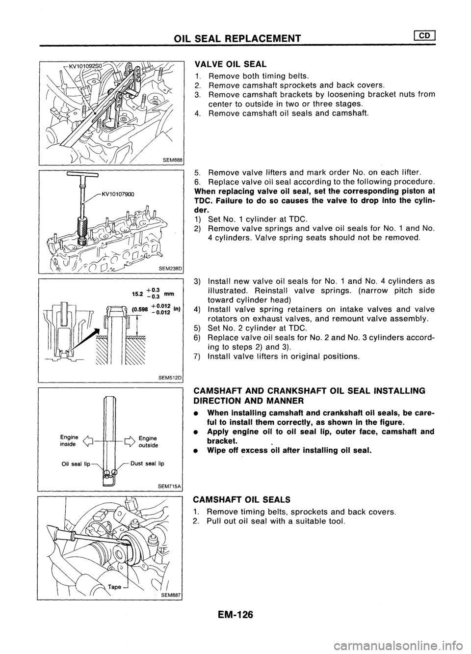
Install newvalve oilseals forNo.1 andNO.4 cylinders as
illustrated. Reinstallvalvesprings. (narrowpitchside
toward cylinder head)
Install valvespring retainers onintake valves andvalve
rotators onexhaust valves,andremount valveassembly.
Set NO.2 cylinder at
TOG.
Replace valveoilseals forNo.2 andNo.3 cylinders accord-
ing tosteps 2)and 3).
Install valvelifters inoriginal positions.
5.
Remove valveliftersandmark order No.oneach lifter.
6. Replace valveoilseal according tothe following procedure.
When replacing valveallseal, setthe corresponding pistonat
TOe. Failure todo socauses thevalve todrop intothecylin-
der.
1) Set NO.1 cylinder at
TOG.
2) Remove valvesprings andvalve oilseals forNO.1 andNo.
4 cylinders. Valvespring seatsshould notberemoved.
VALVE
OilSEAL
1. Remove bothtiming belts.
2. Remove camshaft sprockets andback covers.
3. Remove camshaft bracketsbyloosening bracketnutsfrom
center tooutside intwo orthree stages.
4. Remove camshaft oilseals andcamshaft.
3)
+0.3
15.2 -0.3
mm
(0598
+0.012
In)
4)
. -0.012
5)
6)
~ 7)
SEM512D
Engine
/'t
inside
Y
r-l'\.
Engine
LV outside CAMSHAFT
ANDCRANKSHAFT OilSEAL INSTALLING
DIRECTION ANDMANNER
• When installing camshaftandcrankshaft oilseals, becare-
ful toinstall themcorrectly, asshown inthe figure.
• Apply engine oiltooil seal lip,outer face,camshaft and
bracket. .
• Wipe offexcess allafter installing oilseal.
Oil seal lip Dust
seallip
SEM715A CAMSHAFT OilSEALS
1. Remove timingbelts,sprockets andback covers.
2. Pull outoilseal withasuitable tool.
EM-126
Page 1309 of 1701

Warpageofsurface:
Less than0.1mm (0.004 in)
SEM595A
_ Mic~rmeter
..;- @f
l ~
--I\"
Y
'~~':-- +x
'~o
rA1-
Center
[gJ
Bottom
Valve guide Valve
SEM244D CYLINDER
HEAD
Disassembly (Cont'd)
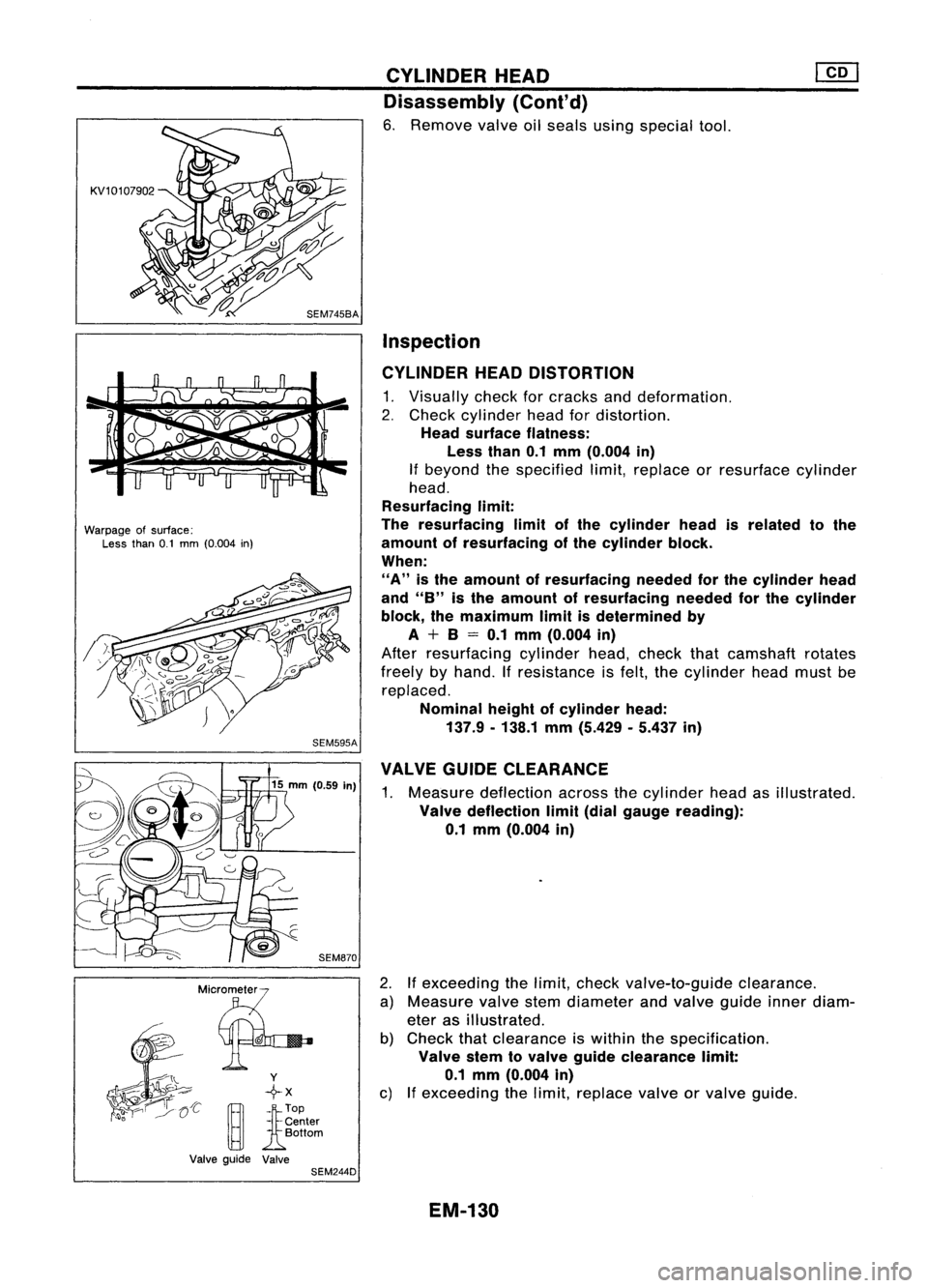
6. Remove valveoilseals usingspecial tool.
Inspection
CYLINDER HEADDISTORTION
1. Visually checkforcracks anddeformation.
2. Check cylinder headfordistortion.
Head surface flatness:
Less than0.1mm (O.004 in)
If beyond thespecified limit,replace orresurface cylinder
head.
Resurfacing limit:
The resurfacing limitofthe cylinder headisrelated tothe
amount ofresurfacing ofthe cylinder block.
When:
"A"
isthe amount ofresurfacing neededforthe cylinder head
and
"8"
isthe amount ofresurfacing neededforthe cylinder
block, themaximum limitisdetermined by
A + 8= 0.1 mm (O.004 in)
After resurfacing cylinderhead,check thatcamshaft rotates
freely byhand. Ifresistance isfelt, thecylinder headmustbe
replaced.
Nominal heightofcylinder head:
137.9. 138.1mm(5.429 .5.437 in)
VALVE GUIDECLEARANCE
1. Measure deflection acrossthecylinder headasillustrated.
Valve deflection limit(dial gauge reading):
0.1 mm (0.004 in)
2. Ifexceeding thelimit, check valve-to-guide clearance.
a) Measure valvestemdiameter andvalve guide innerdiam-
eter asillustrated.
b) Check thatclearance iswithin thespecification .
Valve stemtovalve guide clearance limit:
0.1 mm (O.004 in)
c) Ifexceeding thelimit, replace valveorvalve guide.
EM-130
Page 1312 of 1701
T(Margin thickness)
II
~a
.
,
I
T(Th)
D
L
CYLINDER
HEAD @Q]
Inspection (Cont'd)
VALVE DIMENSIONS
1. Check dimensions ofeach valve. Fordimensions, referto
SDS (EM-171).
2. Correct orreplace anyvalve thatisfaulty .
d •
L-~
SEM188A
3.Valve faceorvalve stemendsurface shouldberefaced by
using avalve grinder.
When valveheadhasbeen worn down to0.5 mm (0.020 in)in
margin thickness, replacethevalve.
Grinding allowance torvalve stemtipis0.5 mm (0.020 in)or
less.
VALVE SPRING SQUARENESS
Check valvespring forsquareness usingasteel square andflat
surface plate.
If
spring isout ofsquare "S"more thanspecified limit,replace
with newone.
Out-at-square: OuterLess than2.1mm (0.083 in)
Inner less than1.9mm (0.075 in)
•
SEM333
VALVE SPRING PRESSURE LOAD
Measure thefree length andthetension ofeach spring. Ifthe
measured valueexceeds thespecified limit,replace spring.
Refer toSDS (EM-172).
EM113 HYDRAULIC VALVELIFTER
1. Check contact andsliding surfaces forwear orscratches .
SEM7238 EM-133
Page 1315 of 1701
![NISSAN ALMERA N15 1995 Service Manual SEM202
SEM731BA
Grade number
Tightening sequence
r
1
@@
~.~.~
o
,..0
W
@
@ @
Facing frontofengine
(position 2)
SEM528DCYLINDER
HEAD
[£Q]
Inspection {Cont'd)
4. Remove cambracket capsan NISSAN ALMERA N15 1995 Service Manual SEM202
SEM731BA
Grade number
Tightening sequence
r
1
@@
~.~.~
o
,..0
W
@
@ @
Facing frontofengine
(position 2)
SEM528DCYLINDER
HEAD
[£Q]
Inspection {Cont'd)
4. Remove cambracket capsan](/manual-img/5/57349/w960_57349-1314.png)
SEM202
SEM731BA
Grade number
Tightening sequence
r
1
@@
~.~.~
o
,..0
W
@
@ @
Facing frontofengine
(position 2)
SEM528DCYLINDER
HEAD
[£Q]
Inspection {Cont'd)
4. Remove cambracket capsandmeasure maximum widthof
plastigage. Camshaft bearingclearance:
Limit
0.1 mm (0.004 in)
5. Ifclearance appearstoexceed thelimit, replace camshaft
or cylinder head.
• Which partstobe replaced shouldbedecided uponafter
measuring thediameters ofthe parts concerned.
Assembly
1. Install valvecomponent parts.
Install valvespring withitsnarrow pitchsidetoward cylinder
head side.
• Always installnewvalve oilseals.
Refer tooil seal replacement.
• Before installing oilseal, install valve-spring seat.
• When installing valve,applyengine oilonthe valve stem
and lipofvalve oilseal.
• Check whether thevalve faceisfree from foreign matter.
• Install valvespring retainers onthe intake sideandvalve
rotators onthe exhaust side.
• Valve rotators cannotbedisassembled.
2. Install camshaft andbrackets andtighten bracket nutstothe
specified torqueintwo orthree stages.
Camshaft-bracket nuts:
~: 18-22 N'm (1.8-2.2 kg-m, 13-16 ft-Ib)
• Tighten bracketfromcenter tooutside.
• Apply sealant tobrackets No.1and No.5.
• When installing "brackets, setcamshaft sothat thepinof
camshaft fronthead isuppermost.
• Install newcamshaft oilseals.
Refer tooil seal replacement.
17.5 (0.689)
o
o
13.0
(0.512)
NO.1 journal bracket No.5journal bracket
Unit: mm(in)
SEM676D
EM-136
Page 1325 of 1701

Feelergauge
SEM599A
SEM506A
Main jOUrnal~
Maintain morethan0.13mm(0.0051 In)
SEM566B CYLINDER
BLOCK
Inspection (Cont'd)
PISTON RINGENDGAP
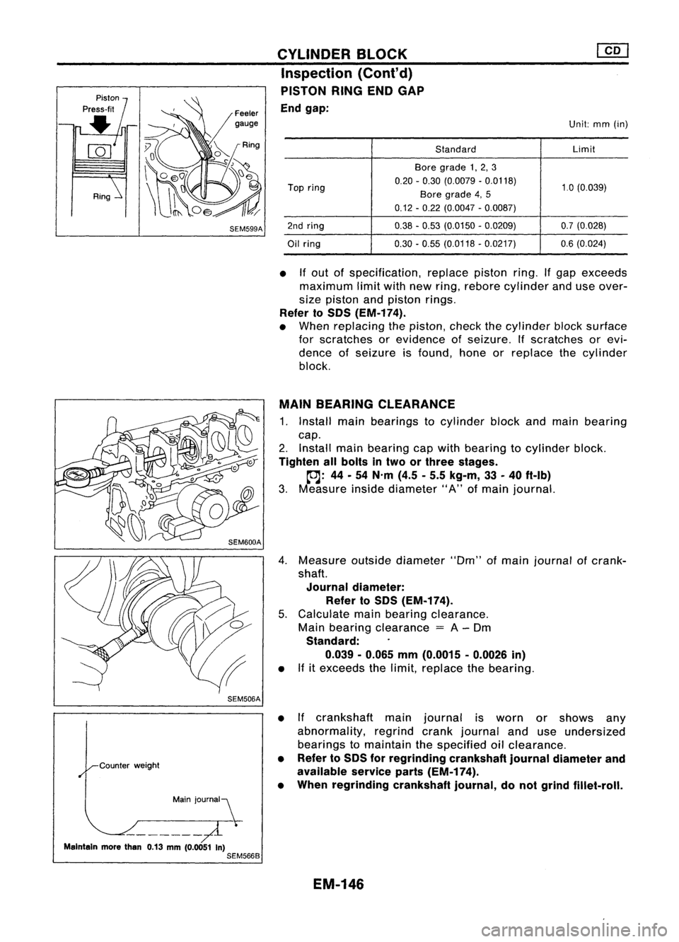
End gap:
Unit:mm(in)
Standard Limit
Bore grade 1,2, 3
Top ring 0.20
-0.30 (0.0079 -0.0118)
1.0(0.039)
Bore grade 4,5
0.12 -0.22 (0.0047 -0.0087)
2nd ring 0.38-0.53 (0.0150 -0.0209) 0.7(0.028)
Oil ring 0.30
-0.55 (0.0118 -0.0217) 0.6(0.024)
• Ifout ofspecification, replacepistonring.Ifgap exceeds
maximum limitwithnewring, rebore cylinder anduseover-
size piston andpiston rings.
Refer toSOS (EM-174).
• When replacing thepiston, checkthecylinder blocksurface
for scratches orevidence ofseizure. Ifscratches orevi-
dence ofseizure isfound, honeorreplace thecylinder
block.
MAIN BEARING CLEARANCE
1. Install mainbearings tocylinder blockandmain bearing
cap.
2. Install mainbearing capwith bearing tocylinder block.
Tighten allbolts intwo orthree stages.
~: 44-54 N'm (4.5-5.5 kg-m, 33-40 ft-Ib)
3. Measure insidediameter" A"ofmain journal.
4. Measure outsidediameter "Om"ofmain journal ofcrank-
shaft.
Journal diameter:
Refer toSOS (EM-174).
5. Calculate mainbearing clearance.
Main bearing clearance
=
A-Om
Standard:
0.039 -0.065 mm(0.0015 -0.0026 in)
• Ifitexceeds thelimit, replace thebearing.
• Ifcrankshaft mainjournal isworn orshows any
abnormality, regrindcrankjournal anduseundersized
bearings tomaintain thespecified oilclearance.
• Refer toSOS forregrinding crankshaftjournaldiameter and
available serviceparts(EM-174).
• When regrinding crankshaftjournal,donot grind fillet-roll.
EM-146
Page 1327 of 1701
![NISSAN ALMERA N15 1995 Service Manual CYLINDERBLOCK [][]
Inspection (Cont'd)
4. Measure outsidediameter "Dp"ofcrankshaft pinjournal.
5. Calculate connecting rodbearing clearance.
Connecting rodbearing clearance
=
C-Op
Standa NISSAN ALMERA N15 1995 Service Manual CYLINDERBLOCK [][]
Inspection (Cont'd)
4. Measure outsidediameter "Dp"ofcrankshaft pinjournal.
5. Calculate connecting rodbearing clearance.
Connecting rodbearing clearance
=
C-Op
Standa](/manual-img/5/57349/w960_57349-1326.png)
CYLINDERBLOCK [][]
Inspection (Cont'd)
4. Measure outsidediameter "Dp"ofcrankshaft pinjournal.
5. Calculate connecting rodbearing clearance.
Connecting rodbearing clearance
=
C-Op
Standard:
0.031 -0.055
mm
(0.0012 -0.0022
in)
• Ifitexceeds thelimit, replace thebearing.
• Ifcrankshaft pinjournal isworn orshows anyabnormality,
regrind crankpinand useundersized bearingstomaintain
the specified oilclearance.
• Refer toSOS forregrinding diameterofcrankshaft pinand
available serviceparts(EM-174).
• When regrinding crankshaft pin,donot grind fillet-roll.
Pin
jOUrnal~
Maintain morethan0.13mm(0.0051 in)
SEM361D
~NO' 1pin journal gradenumber
~NO' 2No.3
__ NO.4
,/
o
J
0 0 ~ NO.1
~ C,"'''ffl.;ghl
SEM705D
Selective
connecting rodbearing
• Ifeither bearings orcrankshaft arebeing replaced withnew
ones, select connecting rodbearings according tothe fol-
lowing table.Grade numbers arepunched ineither Arabic
or Roman numerals.
Crankshaftpinjournal gradenumber
0 1
2
Connecting rodbaring gradenum-
0 12
ber
Identification color
Grade 0:Black
Grade 1:Yellow
Grade 2:Blue
CONNECTING RODANDPISTON PINCLEARANCE
(Small end)
Clearance
(0-
d):
0.025 -0.044
mm
(0.0010 -0.0017
in)
• Ifclearance exceedsthespecifications, replacethebearing.
Clearance
=
0 -d
SEM575B
EM-148
Page 1330 of 1701

CYLINDERBLOCK
Inspection (Cont'd)
Front
0000
•
SEM1768
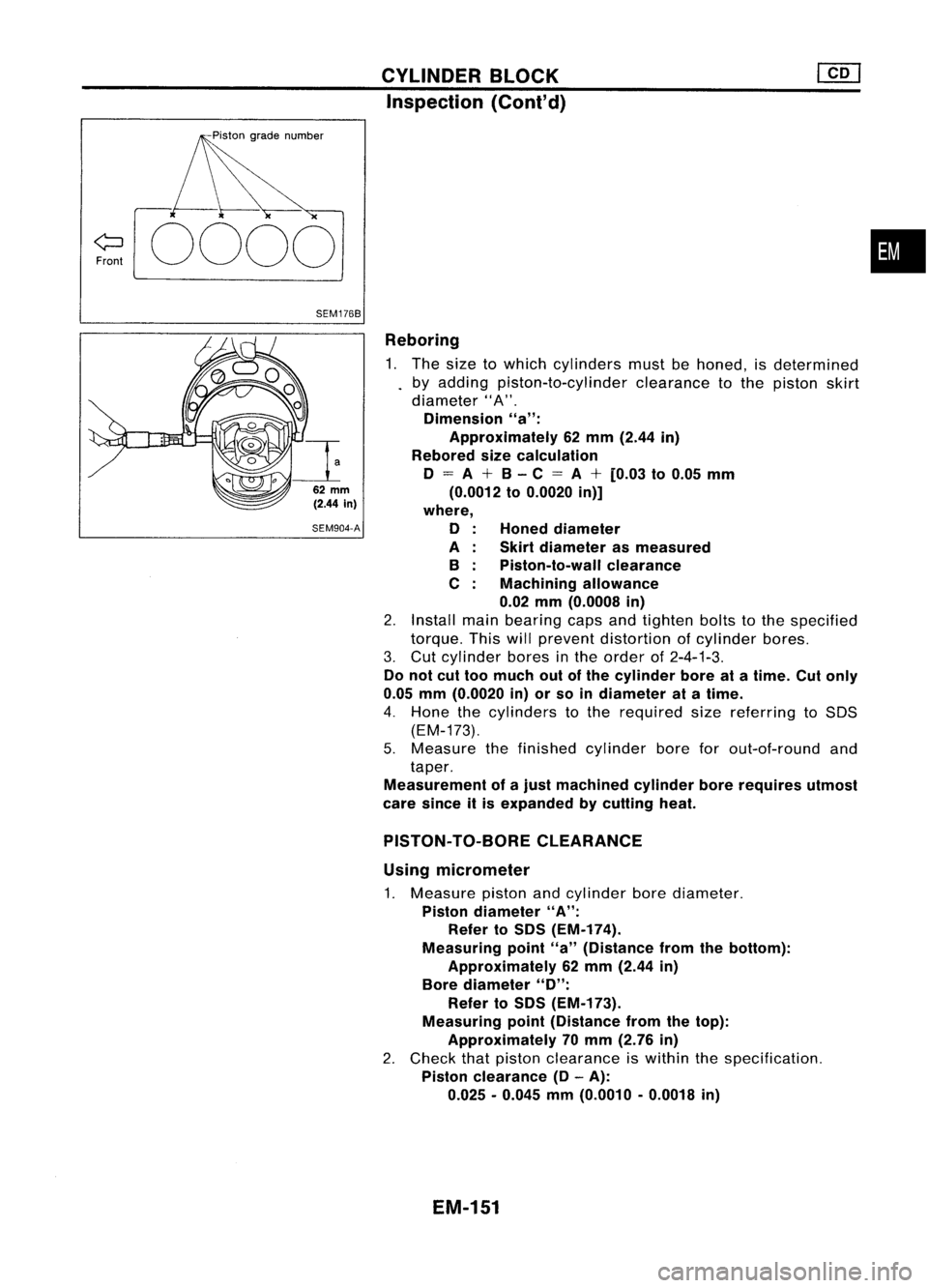
Reboring1. The size towhich cylinders mustbehoned, isdetermined
by adding piston-to-cylinder clearancetothe piston skirt
diameter" A".
Dimension "a":
Approximately 62mm (2.44 in)
Rebored sizecalculation
o
=
A
+
B-C
=
A
+
[0.03 to0.05 mm
(0.0012 to0.0020 in)]
where,
o
A B
C
Honed
diameter
Skirt diameter asmeasured
Piston-to-wall clearance
Machining allowance
0.02 mm(0.0008 in)
2. Install mainbearing capsandtighten boltstothe specified
torque. Thiswillprevent distortion ofcylinder bores.
3. Cut cylinder boresinthe order of2-4-1-3.
Do not cuttoo much outofthe cylinder boreatatime. Cutonly
0.05 mm(0.0020 in)orso indiameter atatime.
4. Hone thecylinders tothe required sizereferring toSOS
(EM-173).
5. Measure thefinished cylinder boreforout-of-round and
taper.
Measurement ofajust machined cylinderborerequires utmost
care since itis expanded bycutting heat.
62
mm
(2.44
in)
SEM904-A
PISTON-TO-BORE CLEARANCE
Using micrometer
1. Measure pistonandcylinder borediameter.
Piston diameter "A":
Refer toSDS (EM-174).
Measuring point"a"(Distance fromthebottom):
Approximately 62mm (2.44 in)
Bore diameter
"0":
Refer toSDS (EM-173).
Measuring point(Distance fromthetop):
Approximately 70mm (2.76 in)
2. Check thatpiston clearance iswithin thespecification.
Piston clearance
(0-
A):
0.025 -0.045 mm(0.0010 -0.0018 in)
EM-151
Page 1331 of 1701
![NISSAN ALMERA N15 1995 Service Manual SEM550
SEM703D CYLINDER
BLOCK
@[]
Inspection (Cont'd)
Using feeler gauge
1. Set piston andfeeler gauge withspring scale.
2. Measure extracting forcewhile pulling upscale slowly.
Feeler gaugeuse NISSAN ALMERA N15 1995 Service Manual SEM550
SEM703D CYLINDER
BLOCK
@[]
Inspection (Cont'd)
Using feeler gauge
1. Set piston andfeeler gauge withspring scale.
2. Measure extracting forcewhile pulling upscale slowly.
Feeler gaugeuse](/manual-img/5/57349/w960_57349-1330.png)
SEM550
SEM703D CYLINDER
BLOCK
@[]
Inspection (Cont'd)
Using feeler gauge
1. Set piston andfeeler gauge withspring scale.
2. Measure extracting forcewhile pulling upscale slowly.
Feeler gaugeused:
0.05 -0.07 mm(0.0020 -0.0028 in)
Extracting force:
7.8 -14.7 N(0.8 -1.5 kg, 1.8-3.3 Ib)
Assembly
PISTON
• Numbers stampedonconnecting rodand capcorrespond to
each cylinder. Careshould betaken toavoid awrong com-
bination including bearingandconnecting roddirection.
KV101070S0
EM156
•
Install newsnap ringonone side ofpiston pinhole.
• When assembling pistonandconnecting rodwith piston pin,
heat piston tobetween 60and 80°C (140and176°F) and
install piston pinwith asuitable tool.
• Install newsnap ring.
• After assembling, ascertainthatpiston swings smoothly.
• Install
piston
ringswithasuitable tool.
Selective topring; When installing newtopring orreplacing
cylinder block,selecttopring toadjust ringgap.
Punch
marksideup
~r~~
~ Tetl~ntubesetposition
~ ,0
Ql
0
SEM251D
Top
ring grade No. Cylinder
boregrade
1,2,3
No mark 4,
5
S
SEM617
CRANKSHAFT
1. Set main bearings inthe proper position oncylinder block
and main bearing caps.
• Ifeither crankshaft, cylinderblockormain bearing isreused
again, itis necessary tomeasure mainbearing clearance.
• Upper bearings (cylinderblockside)haveoilgroove.
• Apply newengine oiltobearing surfaces.
EM-152