Page 1160 of 1701

A16-21
N.m ~/
(1.6 •2.1 kg-m,
12 -15
ft.lb)
ENGINE
COOLING SYSTEM
Cooling SystemInspection (Cont'd)
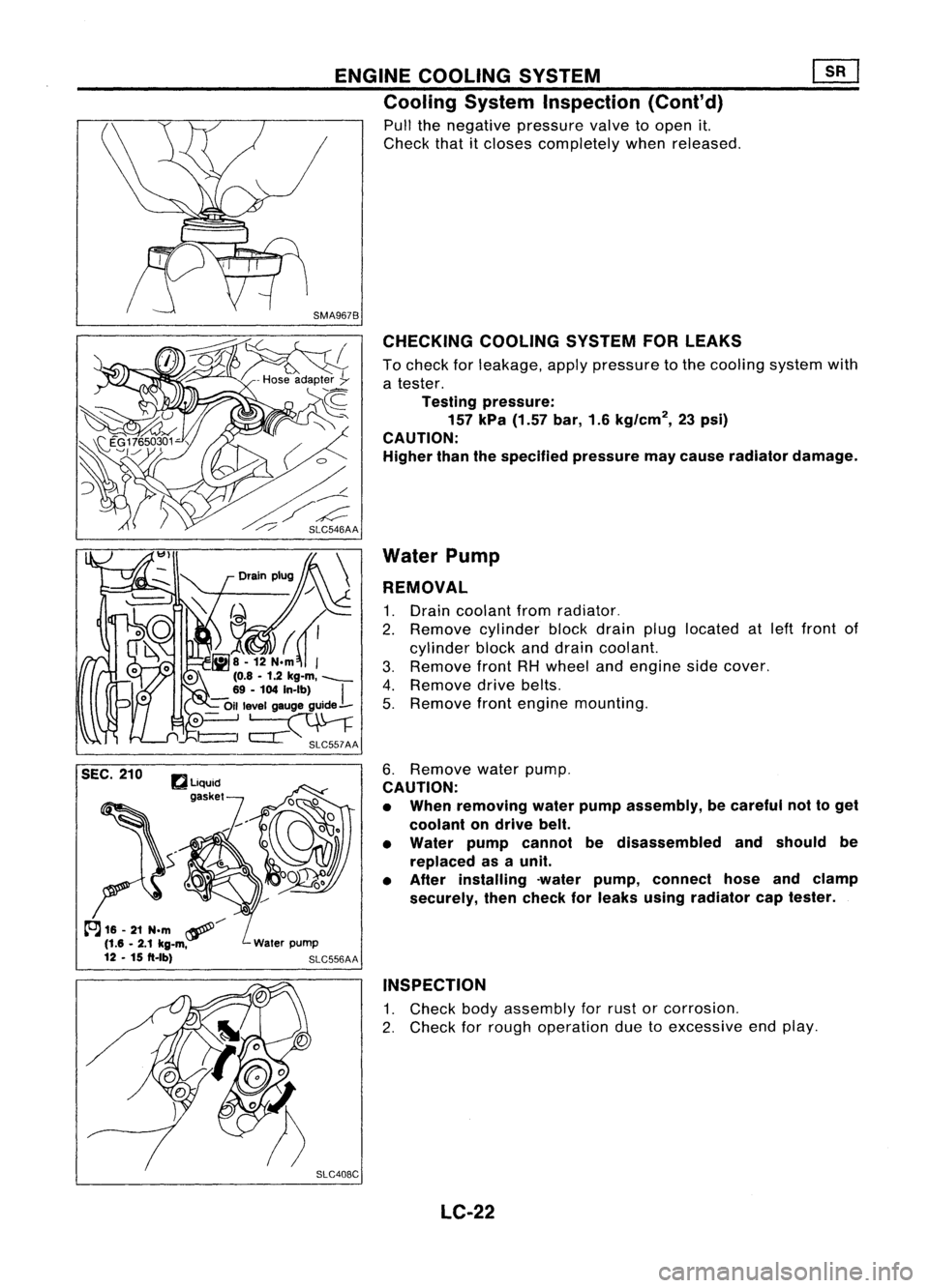
Pull thenegative pressure valvetoopen it.
Check thatitcloses completely whenreleased.
CHECKING COOLINGSYSTEMFORLEAKS
To check forleakage, applypressure tothe cooling systemwith
a tester.
Testing pressure:
157 kPa (1.57 bar,1.6kg/cm
2,
23psi)
CAUTION:
Higher thanthespecified pressuremaycause radiator damage.
Water Pump
REMOVAL
1. Drain coolant fromradiator.
2. Remove cylinderblockdrain pluglocated atleft front of
cylinder blockanddrain coolant.
3. Remove frontRHwheel andengine sidecover.
4. Remove drivebelts.
5. Remove frontengine mounting.
6. Remove waterpump.
CAUTION:
• When removing waterpumpassembly, becareful nottoget
coolant ondrive belt.
• Water pumpcannot bedisassembled andshould be
replaced asaunit.
• After installing -waterpump, connect hoseandclamp
securely, thencheck forleaks using radiator captester.
INSPECTION
1. Check bodyassembly forrust orcorrosion.
2. Check forrough operation duetoexcessive endplay.
SLC408C LC-22
Page 1170 of 1701

ENGINECOOLING SYSTEM
System Check
WARNING:
Never remove theradiator capwhen theengine ishot; serious
burns couldbecaused byhigh pressure fluidescaping fromthe
radiator.
Wrap athick cloth around capandcarefully loosenita quarter
turn torelease built-uppressure. Thenremove thecap com-
pletely.
CHECKING COOLINGSYSTEMHOSES
Check hosesforimproper attachment, leaks,cracks, damage,
loose connections, chafinganddeterioration.
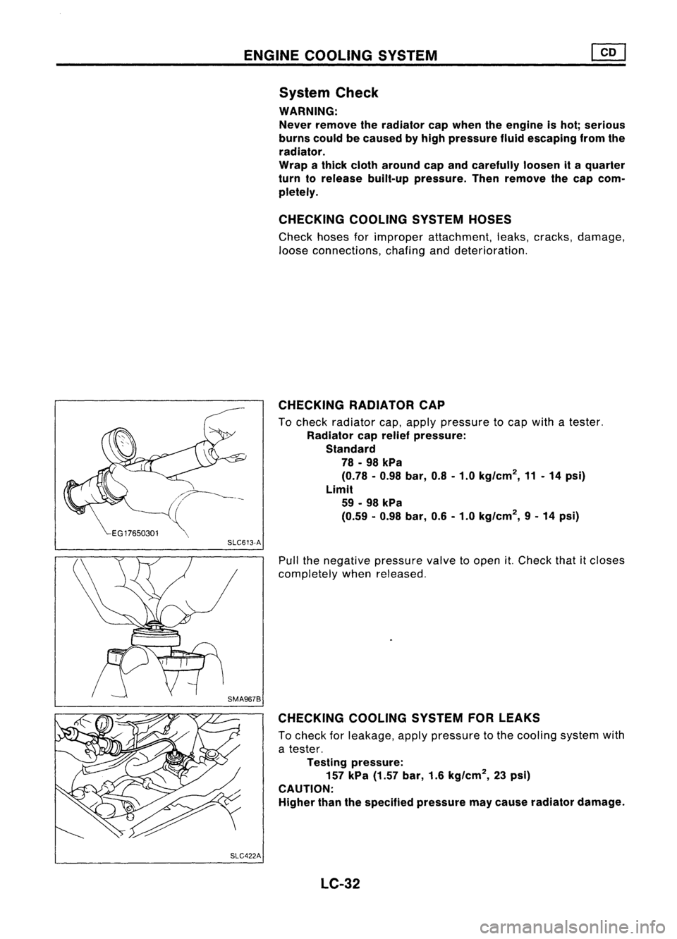
CHECKING RADIATORCAP
To check radiator cap,apply pressure tocap with atester.
Radiator caprelief pressure:
Standard 78 -98 kPa
(0.78 -0.98 bar,0.8-1.0 kg/cm
2,
11-14 psi)
Limit 59 -98 kPa
(0.59 -0.98 bar, 0.6-1.0 kg/cm
2,
9-14 psi)
SLC613-A
Pullthenegative pressure valvetoopen
it.
Check thatitcloses
completely whenreleased.
CHECKING COOLINGSYSTEMFORLEAKS
To check forleakage, applypressure tothe cooling systemwith
a tester.
Testing pressure:
157 kPa (1.57 bar,1.6kg/cm
2,
23psi)
CAUTION:
Higher thanthespecified pressure maycause radiator damage.
SLC422A LC-32
Page 1175 of 1701

ENGINECOOLING SYSTEM
I
GA, SR,CD
I
Radiator (Aluminum type)
r
Sealing rubber~
•
SLC882AB
AIT
model only
r
Upper tank
Sealing rubber~
/"""-.
CJ~~ /~.........."-. '-.. ....,
1I
. / -~ '-""", /~Oil coolersecuring nut-
~ ~,>" (
6<,~8 •
12 N.m
(0.8•1.2 kg-m,
69-104
In-Ib)
@
0..~
~>..
!--Conicalwasher~
, ~I"~"-
Washer
/ /~, ,-O-ring~
Lower tank
-.I
I/' ,_
Oil cooler
o
,
SEC.
214
1.5(0.059)
H"
=
7.6
(0.299)
Unit: mm(in)
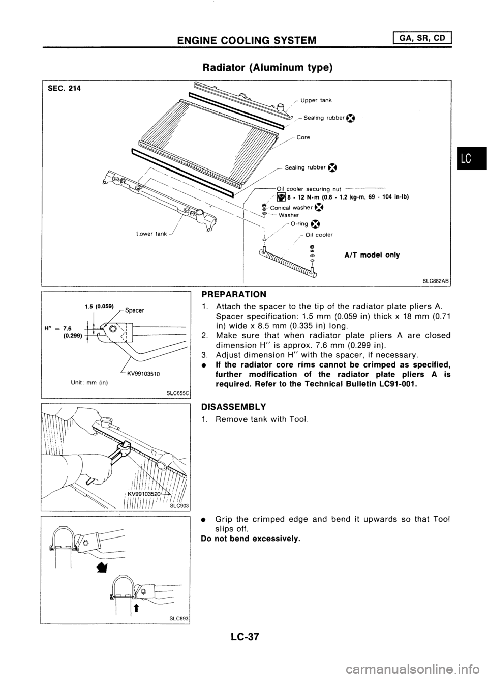
PREPARATION
1. Attach thespacer tothe tipofthe radiator platepliers A.
Spacer specification: 1.5mm (0.059 in)thick x18 mm (0.71
in) wide x8.5 mm (0.335 in)long.
2. Make surethatwhen radiator platepliers Aare closed
dimension H"isapprox. 7.6mm (0.299 in).
3. Adjust dimension H"with thespacer, ifnecessary.
• Ifthe radiator corerimscannot becrimped asspecified,
further modification ofthe radiator platepliers Ais
required. Refertothe Technical BulletinLC91-001.
SLC655C
D1SASSEMBL Y
1. Remove tankwithTool.
• Grip thecrimped edgeandbend itupwards sothat Tool
slips off.
Do not bend excessively.
*
LC-37
Page 1197 of 1701
TIMINGCHAIN
WITH VTC
SEC. 111.120.130.135
~~
\£It''J
132.'.152.•(13 .... 15.... 97.&6 .112.12)
SEM069FB
CD
Upper timing chain
@
Upper timing chaintensioner
@
VTCcamshaft sprocket(Intake)
@
Camshaft sprocket(Exhaust)
@
O-ring
@
Idler shaft
(J)
Idlersprocket
@
Lower timing chaintensioner
@
Gasket
@)
Slack sidetiming chainguide
@
Timing chaintension guide
@
Lower timing chain
EM-18 @
Crankshaft sprocket
@
Oilpump drivespacer
@
Front cover
@
Oilseal
@
Crankshaft pulley
@
Cylinder headfrontcover
Page 1198 of 1701
WITHOUT VTC
SEC. 111.120.130.135
G)
Upper timing chain
@
Upper chaintensioner
@
Camshaft sprocket(Intake)
@
Camshaft sprocket(Exhaust)
@)
a-ring
@
Idler shaft
TIMING
CHAIN
(j)
Idler sprocket
@
Lower chaintensioner
@
Gasket
@
Slack sidetiming chaingUide
@
Timing chainguide
@
Lower timing chain
EM-19
~:
N.m
(kg-m,
in-lb)
~ :N'm
(kg-m, ft-Ib)
~ :Apply
liquidgasket.
fJ :
Lubricate withnew
engine oil.
SEM068FA
@
Crankshaft sprocket
@
Oilpump drivespacer
@)
Front cover
@
Oilseal
@
Crankshaft pulley
@
Cylinder headfrontcover
•
Page 1201 of 1701
Slackside
chain gUide SEM081FTIMING
CHAIN
Removal (Coni'd)
35. Remove enginefrontmounting.
36. Remove enginefrontmounting bracket.
37. Remove frontcover boltsandfront cover asshown.
*1:
Located onengine frontmounting bracket
*2: Located onwater pump
*3: Located onpower steering pumpadjusting bar
38. Remove idlersprocket.
39. Remove lowertiming chain.
40. Remove oilpump drivespacer.
41. Remove chainguides.
42. Remove crankshaft sprocket.
EM-22
Page 1202 of 1701
TIMINGCHAIN
Inspection
Check forcracks andexcessive wearatroller links.Replace if
necessary.
•
SEM1190
No. 1cylinder atTDC
Installation
1. Position crankshaft sothat No.1piston isat TOC andkey
way isat 12 o'clock.
a. Install crankshaft sprocket.
• Make suremating marksoncrankshaft sprocketfacefront
of engine.
b. Install oilpump drivespacer.
SEM377CC
--40
rollers
2.
Install chainguide.
3. Install crankshaft sprocketandlower timing chain.
• Settiming chainbyaligning itsmating markwiththeone on
crankshaft sprocket.
• Make suresprocket's matingmarkfaces engine front.
• The number oflinks between alignment marksare thesame
for the leftand ri.Qht sides. Eithersidecanbeused during
alignment withthesprocket.
SEM127F
/
Same number link
///
40 rollers-
• :Mating mark(different color)
EM-23
Page 1203 of 1701

TIMINGCHAIN ~
Installation (Cont'd)
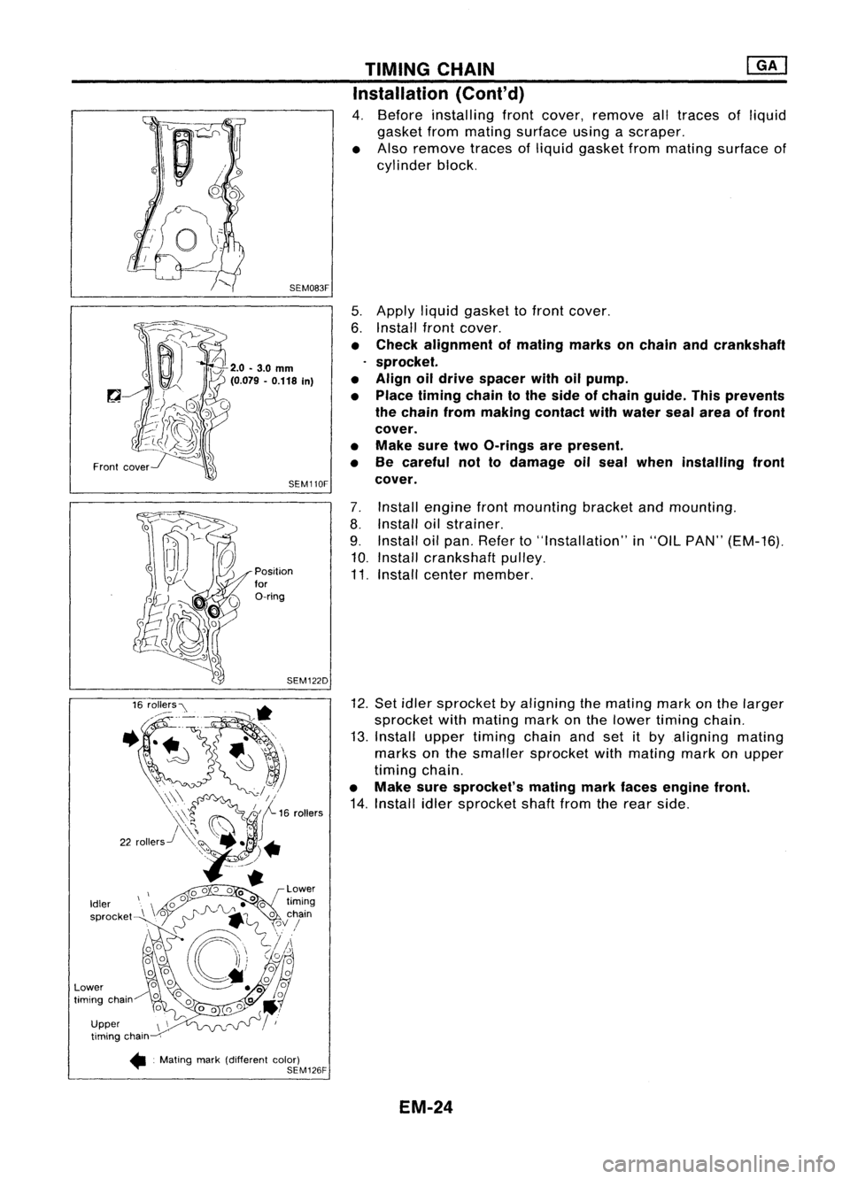
4. Before installing frontcover, remove alltraces ofliquid
gasket frommating surface usingascraper.
• Also remove tracesofliquid gasket frommating surface of
cylinder block.
5. Apply liquidgasket tofront cover.
6. Install frontcover.
• Check alignment ofmating marksonchain andcrankshaft
sprocket.
• Align oildrive spacer withoilpump.
• Place timing chaintothe side ofchain guide. Thisprevents
the chain frommaking contact withwater sealarea offront
cover.
• Make suretwoO-rings arepresent.
• Be careful nottodamage oilseal when installing front
cover.
7. Install engine frontmounting bracketandmounting.
8. Install oilstrainer.
9. Install oilpan. Refer to"Installation" in"OIL PAN" (EM-16).
10. Install crankshaft pulley.
11. Install center member.
12. Set idler sprocket byaligning themating markonthe larger
sprocket withmating markonthe lower timing chain.
13. Install uppertiming chainandsetitby aligning mating
marks onthe smaller sprocket withmating markonupper
timing chain.
• Make suresprocket's matingmarkfaces engine front.
14. Install idlersprocket shaftfromtherear side.
SEM083F
SEM110F
SEM122D
Position
for
O-ring
Front
cover
Upper timing chain
•. Mating mark(different color)
SEM126F
Idler
sprocket
Lower
timing chain
EM-24