Page 1098 of 1701

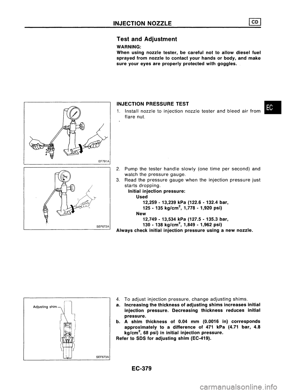
EF791AINJECTION
NOZZLE
Test andAdjustment
WARNING:
When usingnozzle tester,becareful nottoallow diesel fuel
sprayed fromnozzle tocontact yourhands orbody, andmake
sure your eyes areproperly protected withgoggles .
INJECTION PRESSURE TEST
1. Install nozzle toinjection nozzletesterandbleed airfrom
flare nut.
•
SEF672A
2.
Pump thetester handle slowly(onetime persecond) and
watch thepressure gauge.
3. Read thepressure gaugewhentheinjection pressure just
starts dropping.
Initial injection pressure:
Used 12,259 -13,239 kPa(122.6 -132.4 bar,
125 -135 kg/cm
2,
1,778•1,920 psi)
New 12,749 -13,534 kPa(127.5 -135.3 bar,
130 -138 kg/cm
2,
1,849•1,962 psi)
Always checkinitialinjection pressure usinganew nozzle.
Adjusting shim
SEF673A
4.
Toadjust injection pressure, changeadjusting shims.
a. Increasing thethickness ofadjusting shimsincreases initial
injection pressure. Decreasing thicknessreducesinitial
pressure.
b. Ashim thickness of0.04 mm(0.0016 in)corresponds
approximately toadifference of471 kPa (4.71 bar,4.8
kg/cm
2,
68psi) ininitial injection pressure.
Refer toSDS foradjusting shim(EC-419).
EC-379
Page 1099 of 1701
INJECTIONNOZZLE ~
Test andAdjustment (Cont'd)
LEAKAGE TEST
1. Maintain thepressure atabout 981to1,961 kPa(9.8to19.6
bar, 10to20 kg/cm
2,
142to284 psi) below initialinjection
pressure.
2. Check thatthere isno dripping fromthenozzle tiporaround
the body.
Good
Faulty
SEF674A
3.Ifthere isleakage, clean,overhaul orreplace nozzle.
Good
I
Wrong
•
EF794 SPRAY
PATTERN TEST
1. Pump thetester handle onetime persecond.
2. Check thespray pattern .
3. Ifthe spray pattern isnot correct, cleanorreplace nozzle.
EC-380
Page 1110 of 1701
TROUBLEDIAGNOSES
Quick-glow System(Cont'd)
DESCRIPTION
Engine coolant temperature sensor(ECTS)
The engine coolant temperature sensordetects enginecoolant
temperature andtransmits asignal tothe ECM.
Electrical resistance ofthe thermistor decreases inresponse to
the temperature rise.
Key-in switch
The key-in switch isbuilt intothekey cylinder. TheECM detects
the key position andcontrols thekey-in glowsystem.
SEF938P
EC-391
•
Page 1118 of 1701

SYSTEMDESCRIPTION TROUBLE
DIAGNOSES
Partial LoadAdvance (PLA)Control
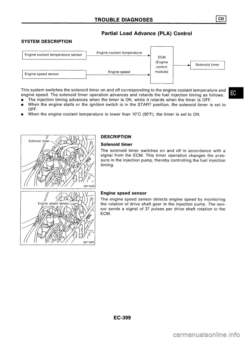
This system switches thesolenoid timeronand offcorresponding tothe engine coolant temperature and
engine speed.Thesolenoid timeroperation advancesandretards thefuel injection timingasfollows:
• The injection timingadvances whenthetimer isON, while itretards whenthetimer isOFF.
• When theengine stallsorthe ignition switchisin the START position, thesolenoid timerisset to
OFF.
• When theengine coolant temperature islower than10°C(50°F), thetimer isset toON.
Engine
coolant temperature sensor
Engine speedsensor Engine
coolant temperature
Engine speed
ECM
(Engine control
module) Solenoid
timer
•
DESCRIPTION
Solenoid timer
The solenoid timerswitches onand offinaccordance witha
signal fromtheECM. Thistimer operation changesthepres-
sure inthe injection pump,thereby controlling thefuel injection
timing.
Engine speedsensor
The engine speedsensor detects enginespeedbymonitoring
the rotation ofdrive shaftgearinthe injection pump.Thesen-
sor sends asignal of37 pulses perdrive shaftrotation tothe
ECM.
EC-399
Page 1122 of 1701
If
NG, replace powersteering oilpressure switch.
Solenoid
timer
1. Disconnect solenoidtimerharness connector.
2. Apply battery voltage tosolenoid timerterminals andlisten
for operating sound.
•
No
Operating
sound
Yes
Condition
With battery voltage applied
Without batteryvoltage applied
TROUBLE
DIAGNOSES ~
Partial LoadAdvance (PLA)Control (Cont'd)
COMPONENT INSPECTION
Engine speedsensor
1. Disconnect enginespeedsensor harness connector.
2. Check resistance betweenterminals
@
and
CID.
Resistance: Approximately 1.6Q
If
NG, replace fuelpump.
EC-403
Page 1123 of 1701
TROUBLEDIAGNOSES
Cooling FanControl
SYSTEM DESCRIPTION
Vehicle speedsensor Vehicle
speed
Engine coolant temperature sensorEngine
coolant temperature
ECM
(Engine
control module) Cooling
fan
relay(s)
Air conditioner switch Air
conditioner "ON"signal
The ECM controls thecooling fancorresponding tothe vehicle speed,engine coolant temperature, air
conditioner systempressure andairconditioner ONsignal. Thecontrol system has3-step control
[HIGH/LOW/OFF].
Operation
SEF953P
20
80
(12) (50)
Vehicle speedkmfh(MPH)
~ :Cooling fansoperate at"High" speed.
Air
conditioner switchIs"ON".
100 (212)
95 (203)
90 (194)
~LL
:J
0
eZ;
~o
E
2
C
'"
'0
o
U
Q>
c
'5>
c
w
Air
conditioner switchIs"OFF".
100 (212)
95 (203)
90 (194)
Q>
-
... LL
:J
0
~~
~o
E
2
c
'"
'0
o
U
Q>
c
'5>
c:
w 20
80
(12) (50)
Vehicle speedkmfh(MPH)
o :
Cooling fansdonot operate.
1222l:
Cooling fansoperate at"Low" speed.
EC-404
Page 1138 of 1701

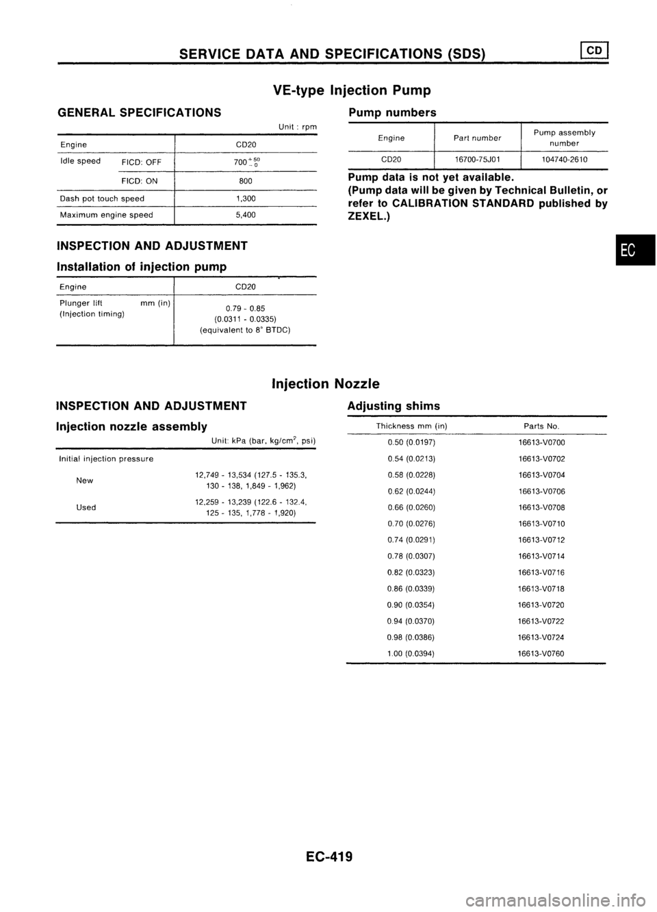
SERVICEOATAAND SPECIFICATIONS (SOS)
GENERAL SPECIFICATIONS
Engine CD20VE-type
Injection Pump
Pump numbers
Unit: rpm
EnginePartnumber Pump
assembly
number
Idle speed
FICO:OFF 700~~O CD20
16700-75J01 104740-2610
INSPECTION ANDADJUSTMENT
Installation ofinjection pump
FICO:
ON
Dash pottouch speed
Maximum enginespeed
Engine
Plunger lift mm(in)
(Injection timing) 800
1,300
5,400
CD20
0.79 -0.85
(0.0311 -0.0335)
(equivalent to8'BTDC) Pump
dataisnot yetavailable.
(Pump data
will
begiven byTechnical Bulletin,or
refer toCALIBRATION STANDARDpublishedby
ZEXEL.)
•
INSPECTION ANDADJUSTMENT Injection
Nozzle
Adjusting shims
Injection nozzleassembly
Unit:kPa(bar, kg/em', psi)
Initial injection pressure
New
Used 12,749
-13,534 (127.5-135.3,
130 -138,1,849 -1,962)
12,259 -13,239 (122.6-132.4,
125 -135, 1,778 -1,920)
EC-419 Thickness
mm(in) PartsNo.
0.50 (0.0197)
16613-V0700
0.54 (0.0213)
16613-V0702
0.58 (0.0228) 16613-V0704
062 (0.0244) 16613-V0706
0.66 (0.0260) 16613-V0708
0.70 (0.0276) 16613-V0710
0.74 (0.0291) 16613-V0712
0.78 (0.0307)
16613-V0714
0.82 (0.0323)
16613-V0716
0.86 (0.0339) 16613-V0718
0.90 (0.0354) 16613-V0720
0.94 (0.0370)
16613-V0722
0.98 (0.0386) 16613-V0724
1.00 (0.0394) 16613-V0760
Page 1150 of 1701
ENGINECOOLING SYSTEM
System Check
WARNING: Never remove theradiator capwhen theengine ishot; serious
burns couldbecaused byhigh pressure fluidescaping fromthe
radiator.
Wrap athick cloth around capandcarefUlly loosenita quarter
turn torelease built-uppressure. Thenremove thecap com-
pletely.
CHECKING COOLINGSYSTEMHOSES
Check hosesforimproper attachment, leaks,cracks, damage,
loose connections, chafinganddeterioration.
CHECKING RADIATORCAP
To check radiator cap,apply pressure tocap with atester.
Radiator caprelief pressure:
Standard
78 -98 kPa
(0.78 -0.98 bar,0.8-1.0 kg/cm
2,
11-14 psi)
Limit
59 -98 kPa
(0.59 -0.98 bar,0.6-1.0 kg/cm
2,
9-14 psi)
SLC613-A
Pullthenegative pressure valvetoopen it.Check thatitcloses
completely whenreleased.
CHECKING COOLINGSYSTEMFORLEAKS
To check forleakage, applypressure tothe cooling systemwith
a tester.
Testing pressure:
157 kPa (1.57 bar,1.6kg/cm
2,
23psi)
CAUTION: Higher thanthespecified pressure maycause radiator damage.
SLC422A LC-12