Page 1054 of 1701
TROUBLEDIAGNOSIS FORNON-DETECTABLE ITEMS
SYSTEM DESCRIPTION Idle
AirControl Valve(IACV) -Auxiliary Air
Control (AAC)Valve
Camshaft positionsensor Engine
speed
~
I
Amount ofintake air
Mass airflow sensor
I
Engine coolant temperature sensor Engine
coolant temperature
I
Ignition switch Start
signal
I
Throttle position sensor Throttle
"position
I
ECM
Inhibitor switch(A/Tmodels)/ Park/Neutral
position (ECCS
control
!
IACV-AAC valve
I
Neutral position switch(M/Tmodels)
module)
Air conditioner switch Air
conditioner operation
Power steering oilpressure switch Power
steering loadsignal
I
Battery Battery
voltage
Vehicle speedsensor Vehicle
speed
I
l
Cooling fan Cooling
fanoperation
I
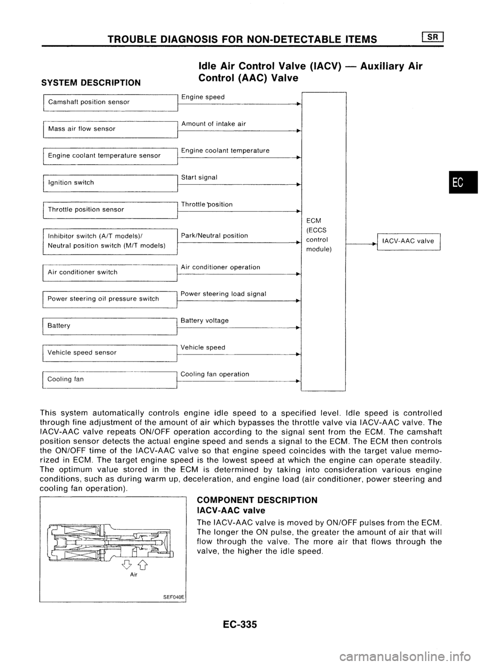
This system automatically controlsengineidlespeed toaspecified level.Idlespeed iscontrolled
through fineadjustment ofthe amount ofair which bypasses thethrottle valveviaIACV-AAC valve.The
IACV-AAC valverepeats ON/OFF operation according tothe signal sentfrom theECM. Thecamshaft
position sensordetects theactual engine speedandsends asignal tothe ECM. TheECM thencontrols
the ON/OFF timeofthe IACV-AAC valvesothat engine speedcoincides withthetarget valuememo-
rized inECM. Thetarget engine speedisthe lowest speedatwhich theengine canoperate steadily.
The optimum valuestored inthe ECM isdetermined bytaking intoconsideration variousengine
conditions, suchasduring warmup,deceleration, andengine load(airconditioner, powersteering and
cooling fanoperation).
COMPONENTDESCRIPTION
IACV-AAC valve
The IACV-AAC valveismoved byON/OFF pulsesfromtheECM.
The longer theONpulse, thegreater theamount ofair that will
flow through thevalve. Themore airthat flows through the
valve, thehigher theidle speed.
Air SEF040E
EC-335
•
Page 1056 of 1701
•IGN TIMING ADJ.
0
TROUBLE
DIAGNOSIS FORNON-DETECTABLE ITEMS
[ill
Idle AirControl Valve(IACV) -Auxiliary Air
Control (AAC)Valve(Cont'd)
DIAGNOSTIC PROCEDURE
-- CONDITION SETIING--
IGN/T FEEDBACK HOLD INSPECTION
START
~i5 ~i5
ECM
E[CONNECTORII
cffb
113
=
= =
MONITOR
CAS. RPM (REF)
IGN TIMING
IDLE POSITION
---
---
800rpm
15BTDC
ON
SEF786KA
MEC768B CHECK
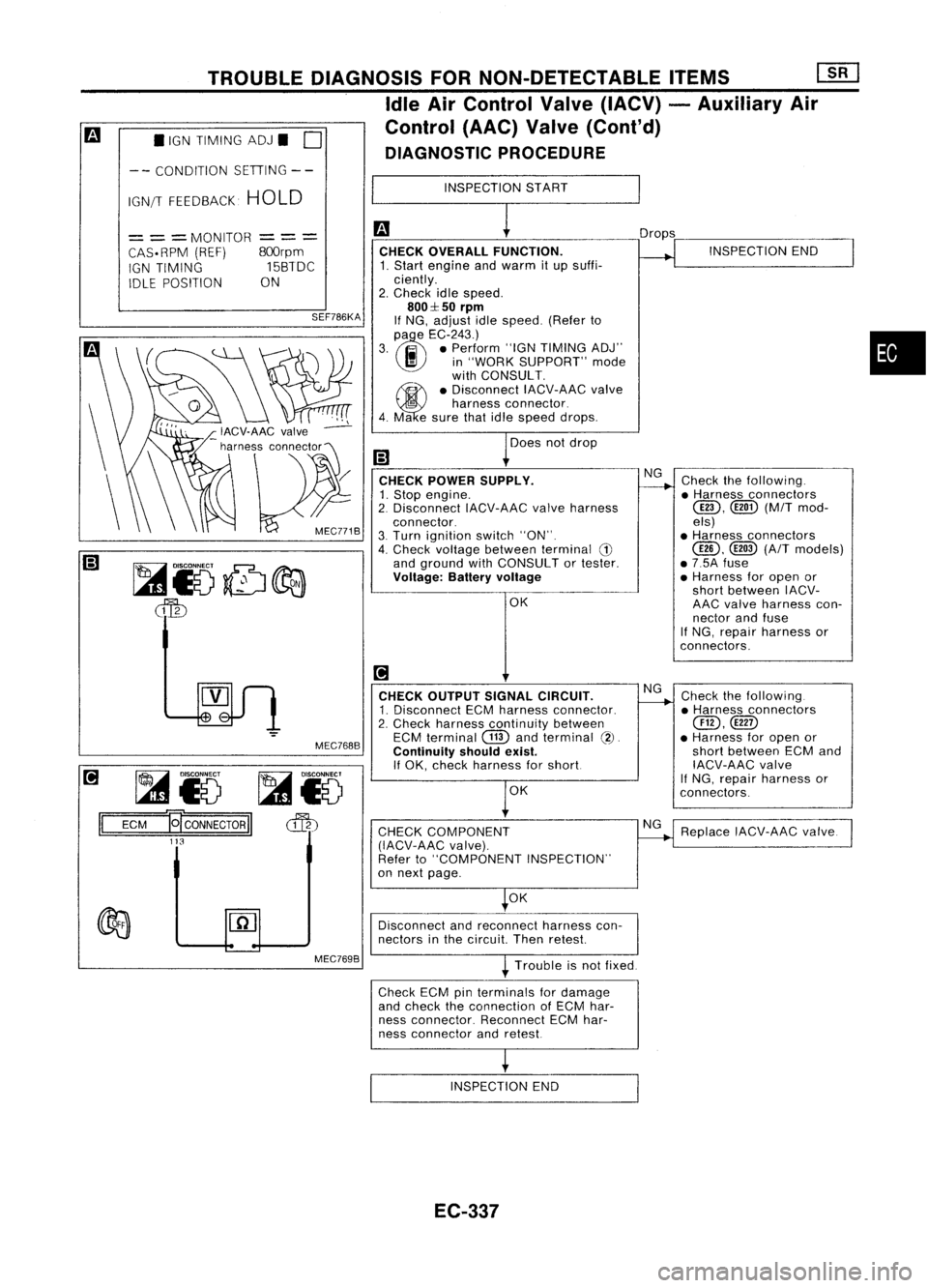
OVERALL FUNCTION.
1. Start engine andwarm itup suffi-
ciently.
2. Check idlespeed.
800::1:50
rpm
If NG, adjust idlespeed. (Referto
(l)
e
EC-243.)
3. .. •Perform "IGNTIMING ADJ"
I!I
in"WORK SUPPORT" mode
with CONSULT.
~ •Disconnect IACV-AACvalve
5
harness connector.
4. Ma esure thatidlespeed drops.
Does notdrop
CHECK POWER SUPPLY.
1. Stop engine.
2. Disconnect IACV-AACvalveharness
connector.
3. Turn ignition switch"ON".
4. Check voltage between terminal
G)
and ground withCONSULT ortester.
Voltage: Batteryvoltage
OK
[!1
CHECK OUTPUT SIGNALCIRCUIT.
1. Disconnect ECMharness connector.
2. Check harness continuity between
ECM terminal
CTID
andterminal
(2).
Continuity shouldexist.
If OK, check harness forshort
OK
CHECK COMPONENT
(IACV-AAC valve).
Refer to"COMPONENT INSPECTION"
on next page.
OK Drops
NG
NG
NG INSPECTION
END
Check thefollowing .
• Harness connectors
@D,
([ill)(M/Tmod-
els)
• Harness connectors
@,
@
(A/T
models)
• 7.5A fuse
• Harness foropen or
short between IACV-
AAC valve harness con-
nector andfuse
If NG, repair harness or
con nectors.
Check thefollowing.
• Harness connectors
@,@D
• Harness foropen or
short between ECMand
IACV-AAC valve
If
NG, repair harness or
connectors.
Replace IACV-AAC valve.
•
Disconnect andreconnect harnesscon-
nectors inthe circuit Thenretest
Trouble isnot fixed.
Check ECMpinterminals fordamage
and check theconnection ofECM har-
ness connector. ReconnectECMhar-
ness connector andretest
INSPECTION END
EC-337
Page 1060 of 1701
MEF023D
•
Refer to"TROUBLE
DIAGNOSES"
i!1
HA sec-
tion. INSPECTION
END
Check thefollowing.
• Harness connectors
@D,@!)
• Harness foropen or
short between IACV-
FICO solenoid valve
harness connector and
air conditioner relay
If NG, repair harness or
connectors.
OK
NG
NG
CHECK
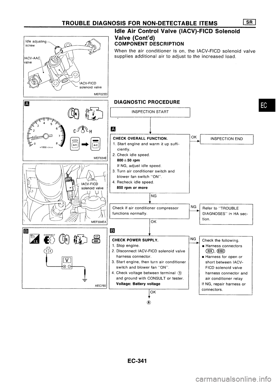
OVERALL FUNCTION.
1. Start engine andwarm itup suffi-
ciently.
2. Check idlespeed.
800:1::50
rpm
If NG, adjust idlespeed.
3. Turn airconditioner switchand
blower fanswitch "ON".
4. Recheck idlespeed.
850 rpm ormore
Check ifair conditioner compressor
functions normally.
DIAGNOSTIC
PROCEDURE
OKNG
OK
INSPECTION
START
CHECK POWER SUPPLY.
1. Stop engine.
2. Disconnect IACV-FICDsolenoidvalve
harness connector.
3. Start engine, thenturnairconditioner
switch andblower fan"ON".
4. Check voltage between terminal
CD
and ground withCONSULT ortester.
Voltage: Batteryvoltage
AEC765
MEF634E
TROUBLE
DIAGNOSIS FORNON-DETECTABLE ITEMS
[]liJ
Idle AirControl Valve(IACV)-FICD Solenoid
Valve (Cont'd)
COMPONENT DESCRIPTION
When theairconditioner ison, the IACV-FICD solenoidvalve
supplies additional airtoadjust tothe increased load.
Idle
adjusting
screw
EC-341
Page 1062 of 1701
TROUBLEDIAGNOSIS FORNON-DETECTABLE ITEMS
Cooling FanControl
SYSTEM DESCRIPTION
Cooling fancontrol
I
Vehicle speedsensor
I
Vehicle speed
Engine coolant temperature EGM
Engine coolant temperature sen- (EGGS
~
sor control
module)
I
Air conditioner switch
I
Air conditio~er "ON"signal
I
Goaling fanrelay(s)
•
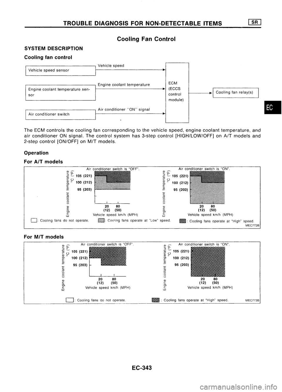
The ECM controls thecooling fancorresponding tothe vehicle speed,engine coolant temperature, and
air conditioner ONsignal. Thecontrol system has3-step control [HIGH/LOW/OFF] onA/T models and
2-step control [ON/OFF] onM/T models.
Operation
For AIT models
Airconditioner switchis"ON".
20 80
(12) (50)
Vehicle speedkm/h(MPH)
m!lll:
Cooling fansoperate at"High" speed.
MEC772B
~u:
~ ?-
105 (221)
~ 0
2i
0
100 (212)
E
2
95(203)
C
'"
o
o
o
20 80
OJ
(12) (50) .~
Vehicle speedkm/h(MPH) ~
~: Cooling fansoperate at"Low" speed.
~LL
.3
?-
105 (221)
~o
2i
0
100 (212)
E
2
95(203)
C
'"
o
o
o
OJ
c:
.0,
c
w
0:
Cooling fansdonot operate.
For MIT models
Airconditioner switchis"OFF".
2080
(12) (50)
Vehicle speedkm/h(MPH)
~
u:
Airconditioner switchis"ON".
::J
0
1il
Z;
105 (221)
OJ
0
E
100(212)
OJ
- 95(203)
C
'"
o
o
o
OJ
c
0,
c
ill
I
20 80
(12) (50)
Vehicle speedkm/h(MPH)
~u:
::J
0
1il ;-
105 (221)
OJ
0
~ 100(212)
<1>
- 95(203)
C
'"
o
o
o
OJ
c
.0,
c
ill
0:
COOling fansdonot operate. m
:Cooling fansoperate at"High" speed.
MEC773B
EC-343
Page 1082 of 1701
TROUBLEDIAGNOSIS FORNON-DETECTABLE ITEMS
Heated Oxygen Sensor(H02S)(Cont'd)
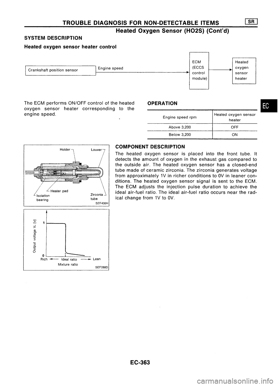
SYSTEM DESCRIPTION
Heated oxygen sensorheatercontrol
ECMHeated
I
Crankshaft positionsensor
I
Engine speed (ECCS
~
oxygen
~
control sensor
module) heater
OPERATION •
--~-
The
ECM performs ON/OFFcontrolofthe heated
oxygen sensorheatercorresponding tothe
engine speed.
Enginespeedrpm
Above 3,200
Below 3,200
Heated
oxygen sensor
heater
OFF
ON
i
Heaterpad
Isolation
bearing Zirconia
i
tube
SEF406H COMPONENT
DESCRIPTION
The heated oxygen sensorisplaced intothefront tube. It
detects theamount ofoxygen inthe exhaust gascompared to
the outside air.The heated oxygen sensorhasaclosed-end
tube made ofceramic zirconia. Thezirconia generates voltage
from approximately 1Vinricher conditions to
av
inleaner con-
ditions. Theheated oxygen sensorsignalissent tothe ECM.
The ECM adjusts theinjection pulseduration toachieve the
ideal air-fuel ratio.Theideal air-fuel ratiooccurs neartherad-
ical change from1Vto
av.
2
1
::>
OJ
~
(5
>
"5
c.
"5
0
:'--
0
-
Rich ---
Ideal
ratio _
Lean
Mixture ratio
SEF288D
EC-363
Page 1093 of 1701
VE-TYPE INJECTION PUMP
SEF779A
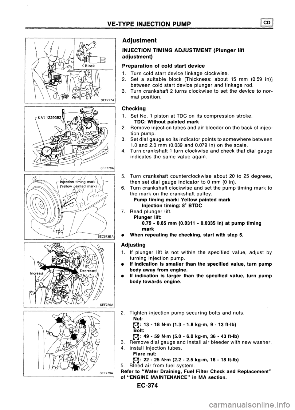
Adjustment
INJECTION TIMINGADJUSTMENT (Plunger
lift
adjustment)
Preparation ofcold start device
1. Turn coldstart device linkage clockwise.
2. Set asuitable block[Thickness: about15mm (0.59 in)]
between coldstart device plunger andlinkage rod.
3. Turn crankshaft 2turns clockwise toset the device tonor-
mal position.
Checking
1. Set NO.1 piston atTDC onitscompression stroke.
TDC: Without paintedmark
2. Remove injection tubesandairbleeder onthe back ofinjec-
tion pump.
3. Set dial gauge soitsindicator pointstosomewhere between
1.0 and 2.0mm (0.039 and0.079 in)onthe scale.
4. Turn crankshaft 1turn clockwise andcheck thatdialgauge
indicates thesame value again.
5. Turn crankshaft counterclockwise about20to25 degrees,
then setdial gauge indicator to0mm (0in).
6. Turn crankshaft clockwiseandsetthe pump timing markto
the mark onthe crankshaft pulley.
Pump timing mark:Yellow painted mark
Injection timing:8
0
BTDC
7. Read plunger lift.
Plunger lift:
0.79 -0.85 mm(0.0311 -0.0335 in)atpump timing
mark
• When repeating thechecking, startwithstep 5.
Adjusting
1. Ifplunger liftisnot within thespecified value,adjust by
turning injection pump.
• Ifindication issmaller thanthespecified value,turnpump
body away fromengine.
• Ifindication islarger thanthespecified value,turnpump
body towards engine.
2. Tighten injection pumpsecuring boltsandnuts.
Nut:
~: 13-18 N.m (1.3-1.8 kg-m, 9-13 ft-Ib)
Bolt:
~: 49-59 N.m (5.0-6.0 kg-m, 36-43 ft-Ib)
3. Remove dialgauge andinstall airbleeder withnewwasher.
4. Install injection tubes.
Flare nut:
~: 22-25 N.m (2.2-2.5 kg-m, 16-18 ft-Ib)
5. Bleed airfrom fuelsystem.
Refer to"Water Draining, FuelFilter Check andReplacement"
of "ENGINE MAINTENANCE" inMA section.
EC-374
Page 1094 of 1701
VE-TVPEINJECTION PUMP ~
Adjustment (Cont'd)
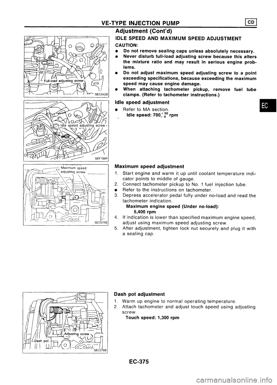
IDLE SPEED ANDMAXIMUM SPEEDADJUSTMENT
CAUTION:
• Donot remove sealingcapsunless absolutely necessary.
• Never disturb full-load adjusting screwbecause thisalters
the mixture ratioandmay result inserious engineprob-
lems.
• Donot adjust maximum speedadjusting screwtoapoint
exceeding specifications, becauseexceeding themaximum
speed maycause engine damage.
• When attaching tachometer pickup,remove fueltUbe
clamps. (Refertotachometer instructions.)
Idle speed adjustment •
• Refer toMA section.
Idle speed:
700~
~o
rpm
SEF156R Maximum speedadjustment
1. Start engine andwarm itup until coolant temperature indi-
cator points tomiddle ofgauge.
2. Connect tachometer pickuptoNO.1 fuelinjection tube.
• Refer tothe instructions ontachometer.
3. Depress accelerator pedalfullyunder no-load andread the
tachometer indication.
Maximum enginespeed(Under no-load):
5,400 rpm
4.
If
indication islower thanspecified maximum enginespeed,
adjust usingmaximum speedadjusting screw.
5. After adjustment, tightenlocknutsecurely andplug itwith
a sealing cap.
Dash potadjustment
1. Warm upengine tonormal operating temperature.
2. Attach tachometer andadjust touchspeed usingadjusting
screw.
Touch speed: 1,300rpm
EC-375
Page 1095 of 1701
Nozzleside
Combustion
chamber side
SEF668A
SEF781A
SEF669A
:S
older ~Adiusting shim
c:,
Nozzlespring
~ '~[;{~I:,""'
pi,",
Nozzle needle~~(''''-
Nozzle bOdyr ~
Nozzle nut)
SEF670A INJECTION
NOZZLE
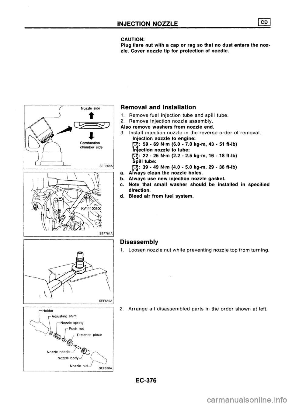
CAUTION: Plug flare nutwith acap orrag sothat nodust enters thenoz-
zle. Cover nozzle tipfor protection ofneedle.
Removal andInstallation
1. Remove fuelinjection tubeandspill tube.
2. Remove injection nozzleassembly.
Also remove washers fromnozzle end.
3. Install injection nozzleinthe reverse orderofremoval.
Injection nozzletoengine:
~: 59-69 N'm (6.0-7.0 kg-m, 43-51 ft-Ib)
Injection nozzletotube:
~: 22-25 N'm (2.2-2.5 kg-m, 16-18 ft-Ib)
Spill tube:
~: 39-49 N'm (4.0-5.0 kg-m, 29-36 ft-Ib)
a. Always cleanthenozzle holes.
b. Always usenew injection nozzlegasket.
c. Note thatsmall washer shouldbeinstalled inspecified
direction.
d. Bleed airfrom fuelsystem.
Disassembly
1. Loosen nozzlenutwhile preventing nozzletopfrom turning.
2. Arrange alldisassembled partsinthe order shown atleft.
EC-376