Page 1234 of 1701

AEM030
SEM062A
SEM291C
SEM367E CYLINDER
BLOCK ~
Inspection (ConI'd)
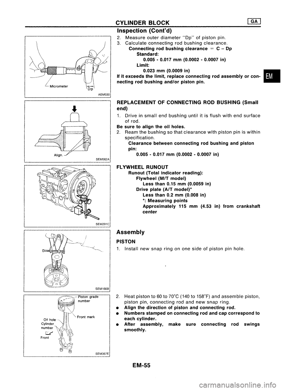
2. Measure outerdiameter lOOp"ofpiston pin.
3. Calculate connecting rodbushing clearance.
Connecting rodbushing clearance
=
C-Dp
Standard: 0.005 •0.017 mm(0.0002 •0.0007 in)
Limit:
0.023 mm(0.0009 in) •
If itexceeds thelimit, replace connecting rodassembly orcon-
necting rodbushing andlorpistonpin.
REPLACEMENT OFCONNECTING RODBUSHING (Small
end)
1. Drive insmall endbushing untilitis flush withendsurface
of rod.
Be sure toalign theoilholes.
2. Ream thebushing sothat clearance withpiston piniswithin
specification.
Clearance betweenconnecting rodbushing andpiston
pin: 0.005 -0.017 mm(0.0002 -0.0007 in)
FLYWHEEL RUNOUT
Runout (Totalindicator reading):
Flywheel (MITmodel)
Less than0.15mm(0.0059 in)
Drive plate(AITmodel)*
Less than0.2mm (0.008 in)
*:
Measuring points
Approximately 115mm (4.53 in)from crankshaft
center
Assembly PISTON
1. Install newsnap ringonone side ofpiston pinhole.
2. Heat piston to60 to70°C (140to158°F) andassemble piston,
piston pin,connecting rodand new snap ring.
• Align thedirection ofpiston andconnecting rod.
• Numbers stampedonconnecting rodand capcorrespond to
each cylinder.
• After assembly, makesureconnecting rodswings
smoothly.
EM-55
Page 1236 of 1701

IdentificationNo.
\ca
p
\
NO.1
t.:?
Enginefront
SEM420C CYLINDER
BLOCK
Assembly (Cont'd)
•
Front
Pistonringcompressor
SEM293C
2.
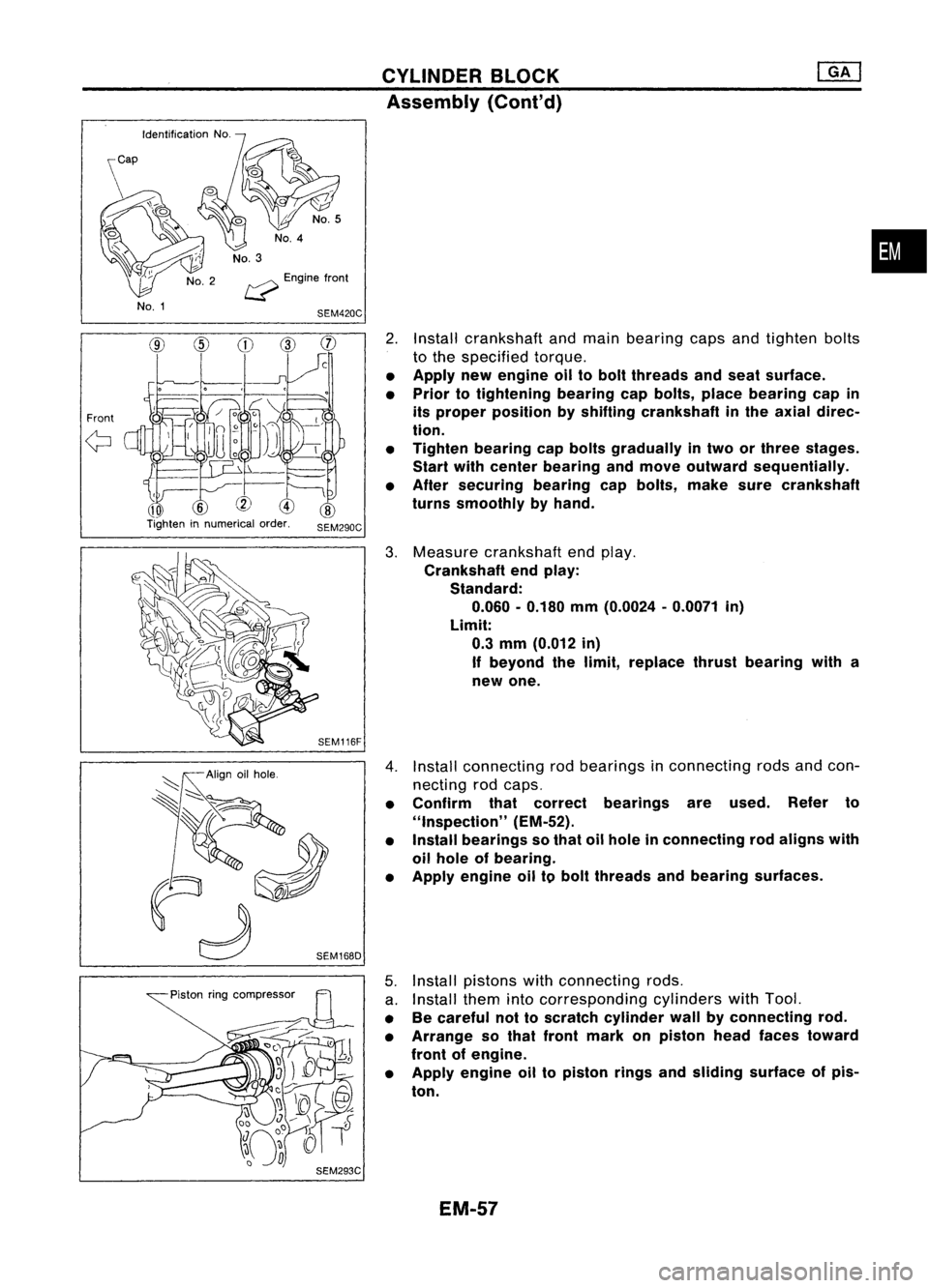
Install crankshaft andmain bearing capsandtighten bolts
to the specified torque.
• Apply newengine oiltobolt threads andseat surface.
• Prior totightening bearingcapbolts, placebearing capin
its proper position byshifting crankshaft inthe axial direc-
tion.
• Tighten bearing capbolts gradually intwo orthree stages.
Start withcenter bearing andmove outward sequentially.
• After securing bearingcapbolts, makesurecrankshaft
turns smoothly byhand.
3. Measure crankshaft endplay.
Crankshaft endplay:
Standard:
0.060 -0.180 mm(0.0024 -0.0071 in)
Limit: 0.3 mm (0.012 in)
If beyond thelimit, replace thrustbearing witha
new one.
4. Install connecting rodbearings inconnecting rodsandcon-
necting rodcaps.
• Confirm thatcorrect bearings areused. Referto
"Inspection" (EM-52).
• Install bearings sothat oilhole inconnecting rodaligns with
oil hole ofbearing.
• Apply engine oiltobolt threads andbearing surfaces.
5. Install pistons withconnecting rods.
a. Install themintocorresponding cylinderswithTool.
• Becareful nottoscratch cylinder wallbyconnecting rod.
• Arrange sothat front mark onpiston headfaces toward
front ofengine.
• Apply engine oiltopiston ringsandsliding surface ofpis-
ton.
EM-57
Page 1252 of 1701
Engine~
front
Y--J
SEM721E
SEM984C
~ Crankshaft
!..--..V
side
Crankshaft sprocket
SEM470E TIMING
CHAIN
Removal (Cont'd)
30. Remove frontengine mounting.
31. Remove frontcover andoilpump drivespacer.
• Inspect foroilleakage atfront oilseal. Replace sealifoil
leak ispresent.
32. Remove timingchainguides andtiming chain.
Inspection
Check forcracks andexcessive wearatroller links.Replace
chain ifnecessary.
Installation
1. Install crankshaft sprocketoncrankshaft.
• Make surethatmating marksoncrankshaft sprocketface
front ofengine.
EM-73
•
Page 1254 of 1701
Wipeoff
liquid gasket
SEM214FTIMING
CHAIN ~
Installation (Cont'd)
6. Install oilpump drivespacer andfront cover .
• Wipe offexcessive liquidgasket.
•
7. Install frontengine mounting.
8. Install crankshaft pulley.
9. Set NO.1 piston atTDG onitscompression stroke.
EM.75
Page 1261 of 1701
OILSEAL REPLACEMENT
VALVE OILSEAL
1. Remove accelerator cable.
2. Remove rockercoverandoilseparator.
3. Remove camshafts andsprockets.
Refer to"Removal" in"TIMING CHAIN"(EM-69).
4. Remove sparkplugs.
5. Install airhose adapter intospark plugholeandapply air
pressure tohold valves inplace. Applyapressure of490
kPa (4.9bar, 5kg/cm
2,
71psi).
6. Remove rockerarm,rocker armguide andshim.
Air SEM077D
7.Remove valvespring withTool.
Piston concerned shouldbeset atTOe toprevent valvefrom
falling.
8. Remove valveoilseal.
9. Apply engine oiltonew valve oilseal andinstall itwith Tool.
FRONT OILSEAL
1. Remove thefollowing parts:
• Engine undercover
• Front RHwheel andengine sidecover
• Drive belts
• Crankshaft pulley
2. Remove frontoilseal.
Be careful nottoscratch frontcover.
SEM997C EM-82
Page 1267 of 1701
SEM925CCYLINDER
HEAD
Disassembly (Cont'd)
12. Remove valveoilseal with asuitable tool.
Inspection
CYLINDER HEADDISTORTION
. Head surface flatness:
Standard Less than0.03mm(0.0012 in)
Limit
0.1 mm (0.004 in)
If beyond thespecified limit,replace orresurface.
Resurfacing limit:
The resurfacing limitofcylinder headisdetermined bythe cyl-
inder block resurfacing inan engine.
Amount ofcylinder headresurfacing is
"A".
Amount ofcylinder blockresurfacing is
"B".
The maximum limitisas follows:
A
+
B
=
0.2 mm (0.008 in)
After resurfacing cylinderhead,check thatcamshaft rotates
freely byhand. Ifresistance isfelt, cylinder headmustbe
replaced.
Nominal cylinderheadheight:
136.9 -137.1 mm(5.390 -5.398 in)
CAMSHAFT VISUALCHECK
Check camshaft forscratches, seizureandwear.
CAMSHAFT RUNOUT
1. Measure camshaft runoutatthe center journal.
Runout (Totalindicator reading):
Standard Less than0.02mm(0.0008 in)
Limit
0.1 mm (0.004 in)
2. Ifitexceeds thelimit, replace camshaft.
EM-88
Page 1271 of 1701

T(Margin thickness)
~I
r
nw
a
III' ~
D
L
-l
d
SEM892B
SEM188A CYLINDER
HEAD
Inspection (Cont'd)
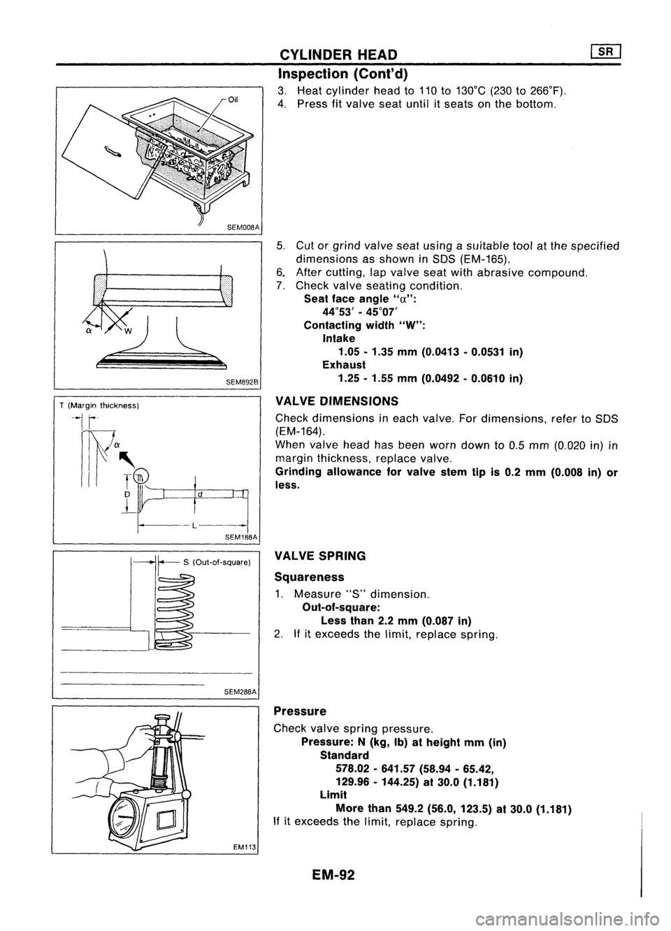
3. Heat cylinder headto110 to130°C (230to266°F).
4. Press fitvalve seatuntil itseats onthe bottom.
5. Cut orgrind valve seatusing asuitable toolatthe specified
dimensions asshown inSDS (EM-165).
6. After cutting, lapvalve seatwithabrasive compound.
7. Check valveseating condition.
Seat faceangle
"u":
44°53' -45°07'
Contacting width
"W":
Intake 1.05 -1.35 mm(0.0413 -0.0531 in)
Exhaust
1.25 -1.55 mm(0.0492 -0.0610 in)
VALVE DIMENSIONS
Check dimensions ineach valve. Fordimensions, refertoSDS
(EM-164).
When valveheadhasbeen worn down to0.5 mm (0.020 in)in
margin thickness, replacevalve.
Grinding allowance forvalve stemtipis0.2 mm (0.008 in)or
less.
SEM288A VALVE
SPRING
Squareness
1. Measure "S"dimension.
Out-of-square:
Less than2.2mm (0.087 in)
2. Ifitexceeds thelimit, replace spring.
EM113 Pressure
Check valvespring pressure.
Pressure: N(kg, Ib)atheight mm(in)
Standard
578.02 -641.57 (58.94-65.42,
129.96 -144.25) at30.0 (1.181)
Limit
More than549.2 (56.0, 123.5) at30.0 (1.181)
If itexceeds thelimit, replace spring.
EM-92
Page 1274 of 1701
![NISSAN ALMERA N15 1995 Service Manual CYLINDERHEAD
ill]
Assembly (Cont'd)
10. Install valvecomponent parts.
• Install valves withlarger diameter headonthe intake side.
•
Wide pitch
Narrow pitch
Paint mark
Cylinder headside
S NISSAN ALMERA N15 1995 Service Manual CYLINDERHEAD
ill]
Assembly (Cont'd)
10. Install valvecomponent parts.
• Install valves withlarger diameter headonthe intake side.
•
Wide pitch
Narrow pitch
Paint mark
Cylinder headside
S](/manual-img/5/57349/w960_57349-1273.png)
CYLINDERHEAD
ill]
Assembly (Cont'd)
10. Install valvecomponent parts.
• Install valves withlarger diameter headonthe intake side.
•
Wide pitch
Narrow pitch
Paint mark
Cylinder headside
SEM085D•
Always usenew valve oilseal.
Refer toOIL SEAL REPLACEMENT.
• Before installing valveoilseal, install valvespring seat.
.' Install valvespring (uneven pitchtype) withitsnarrow
pitched sidetoward cylinder headside(paint mark).
• After installing valvecomponent parts,tapvalve stemtip
with plastic hammer toassure aproper fit.
11. Check hydraulic lashadjusters.
a. Push rocker armathydraulic lashadjuster location, andsee
if rocker armmoves. Ifitmoves atleast 1mm (0.04 in),it
indicates thatthere isair inthe high pressure chamber.
Noise willbeemitted fromhydraulic lashadjuster ifengine
is started without bleeding air.
b. Remove hydraulic lashadjuster anddipinacontainer filled
with engine oil.While pushing plungerasshown infigure,
lightly pushcheck ballusing athin rod. Airiscompletely
bled when plunger nolonger moves.
Air cannot bebled from thistype oflash adjuster byrunning the
engine.
SEM093D
• rEngine oil
- - , t-=1=i
Proper
rod
SEM772C
Rocker arm9UVide
Rock~rarm
Shim
Hydraulic
I
.,h
.dj"'"
i\\ j
12.
Install rocker arms,shims, rockerarmguides andhydrau-
lic lash adjusters.
CAUTION: Install allparts intheir original positions.
SEM202D EM-95