Page 1275 of 1701
/1!!i1*Shim
~ Rocker armguide
Ij9 ~~
Valve collet
~ I:::
Valvespring
l!I
retainer
I!1!i! ~
'Valve spring
~ ~~ ~Valve springseat
j
Valveoilseal ~
Valve
SEM364DCYLINDER
HEAD ~
Assembly (Cont'd)
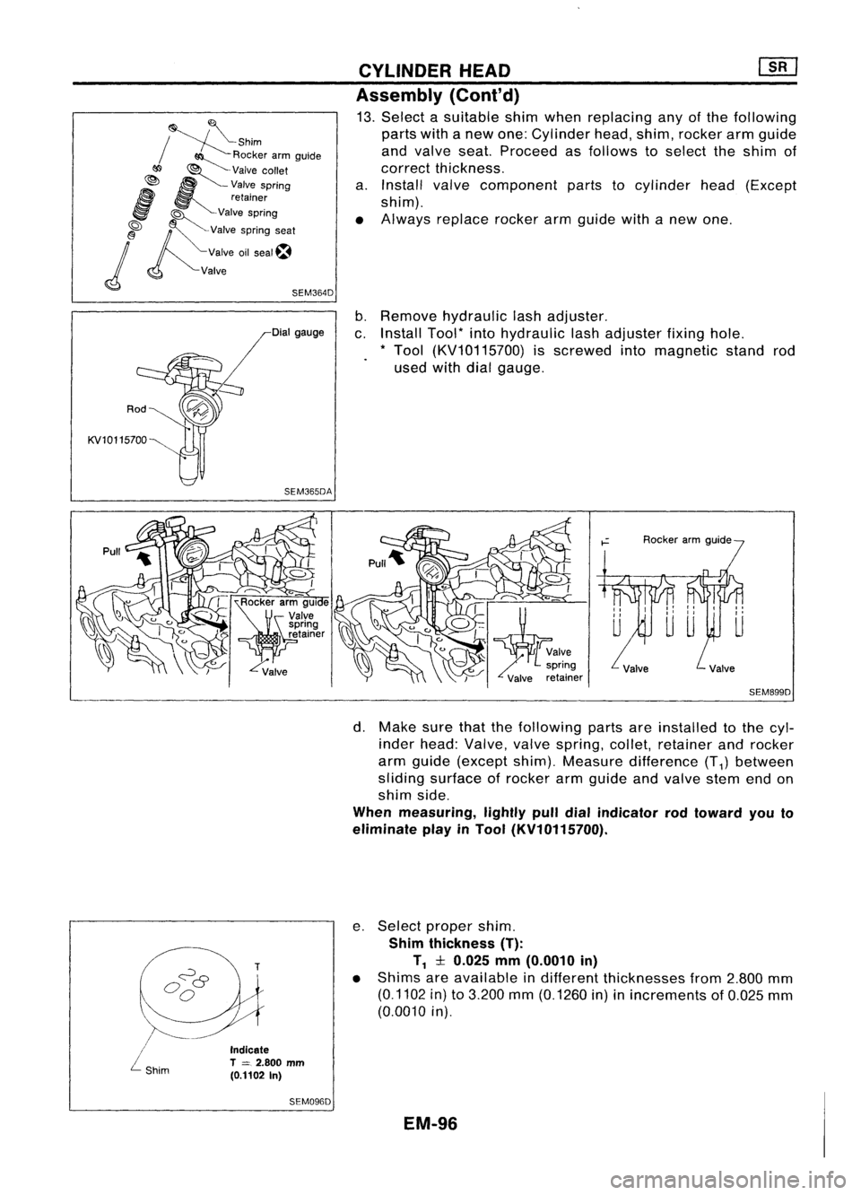
13. Select asuitable shimwhen replacing anyofthe following
parts withanew one: Cylinder head,shim, rocker armguide
and valve seat.Proceed asfollows toselect theshim of
correct thickness.
a. Install valvecomponent partstocylinder head(Except
shim).
• Always replace rockerarmguide withanew one.
Rod
KV10115700 Dial
gauge
SEM365DA
b.
Remove hydraulic lashadjuster.
c. Install Tool*intohydraulic lashadjuster fixinghole.
* Tool (KV10115700) isscrewed intomagnetic standrod
used withdialgauge.
SEM899D
\.
/~-
/
L
shim
Indicate
T
=
2.800 mm
(0.1102 In)
SEM096D
d.
Make surethatthefollowing partsareinstalled tothe cyl-
inder head: Valve, valvespring, collet,retainer androcker
arm guide (except shim).Measure difference (T
1)
between
sliding surface ofrocker armgUide andvalve stemendon
shim side.
When measuring, lightlypulldialindicator rodtoward youto
eliminate playinTool (KV10115700).
e. Select proper shim.
Shim thickness (T):
T
1
:l:0.025 mm(0.0010 in)
• Shims areavailable indifferent thicknesses from2.800 mm
(0.1102 in)to3.200 mm(0.1260 in)inincrements of0.025 mm
(0.0010 in).
EM-96
Page 1278 of 1701
SEM092DENGINE
REMOVAL
WARNING:
• Situate vehicle onaflat and solid surface.
• Place chocks atfront andback ofrear wheels.
• Donot remove engineuntilexhaust systemhascompletely
cooled off.
Otherwise, youmay burn yourself and/orfiremay break out
in fuel line.
• For safety during subsequent steps,thetension ofwires
should beslackened againsttheengine.
• Before disconnecting fuelhose, release fuelpressure from
fuel line.
Refer to"Releasing FuelPressure" inEC section.
• Besure tohoist engine andtransaxle inasafe manner.
• For engines notequipped withengine slingers, attach
proper slingers andbolts described inPARTS CATALOG.
CAUTION:
• When liftingengine, becareful nottostrike adjacent parts,
especially thefollowing: Accelerator wirecasing, brake
lines, andbrake master cylinder.
• Inhoisting theengine, alwaysuseengine slingers inasafe
manner.
Removal
1. Remove engineundercoverandhood.
2. Drain coolant frombothcylinder block,andradiator.
3. Drain engine oilfrom drain plugofoil pan.
4. Remove vacuumhoses,fuelhoses, wires,harness andcon-
nectors andsoon.
5. Remove exhausttubes,balljoints anddrive shafts.
6. Remove radiatorandfans.
7. Remove drivebelts.
8. Remove alternator, compressor andpower steering oil
pump fromengine.
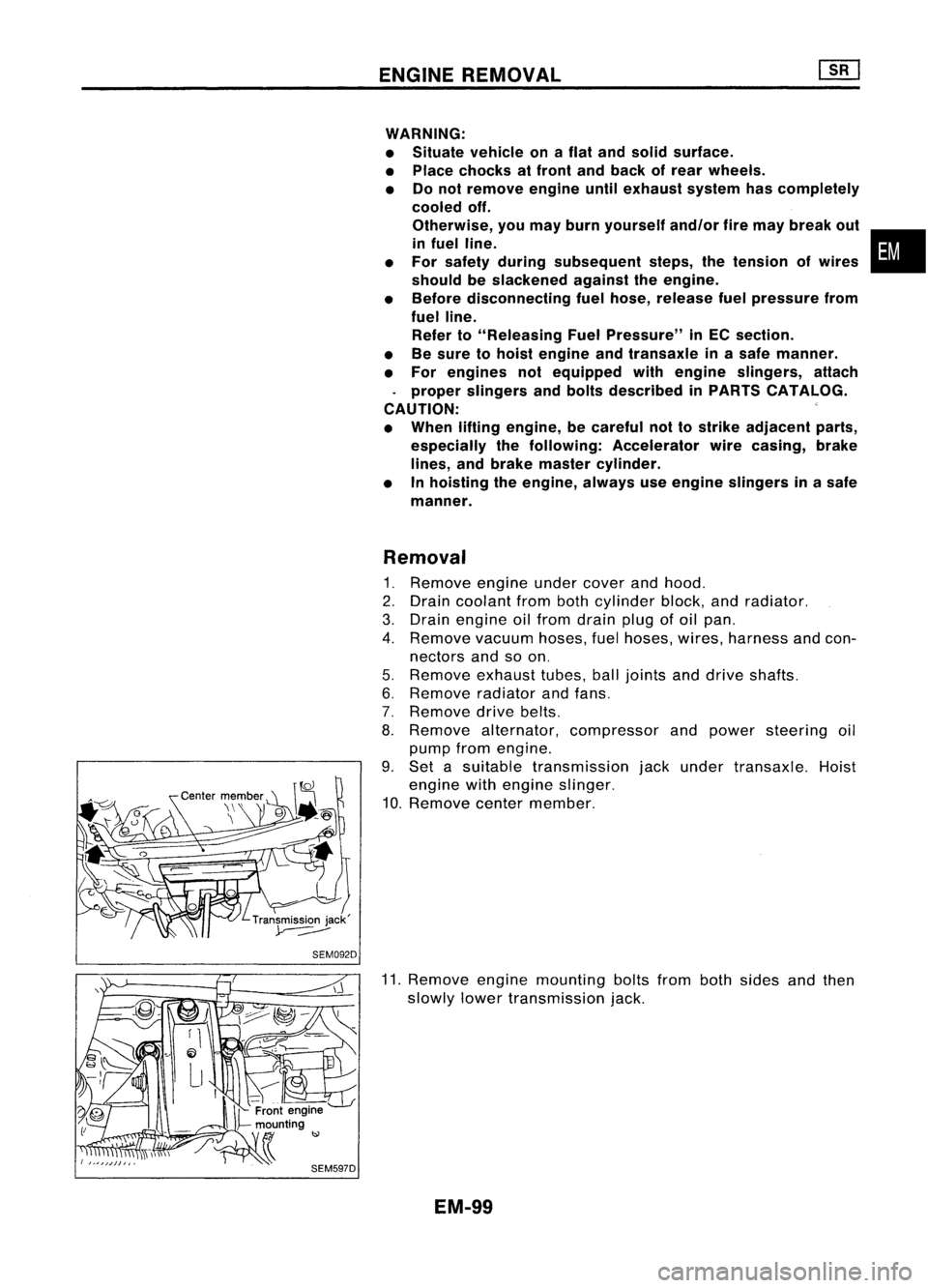
9. Set asuitable transmission jackunder transaxle. Hoist
engine withengine slinger.
10. Remove centermember.
11. Remove enginemounting boltsfrombothsides andthen
slowly lowertransmission jack.
EM-99
•
Page 1285 of 1701
#5
#4 ~
~i1
hole #3~~ \)
#2 ~~,
#1~~~ ~~
12 ~~
Engine front~
SEM685D
SEM964
SEM313D CYLINDER
BLOCK
Inspection (Cont'd)
BEARING CLEARANCE
• Use either ofthe following twomethods, however, method
"A" gives morereliable resultsandispreferred.
Method A(Using boregauge
&
micrometer)
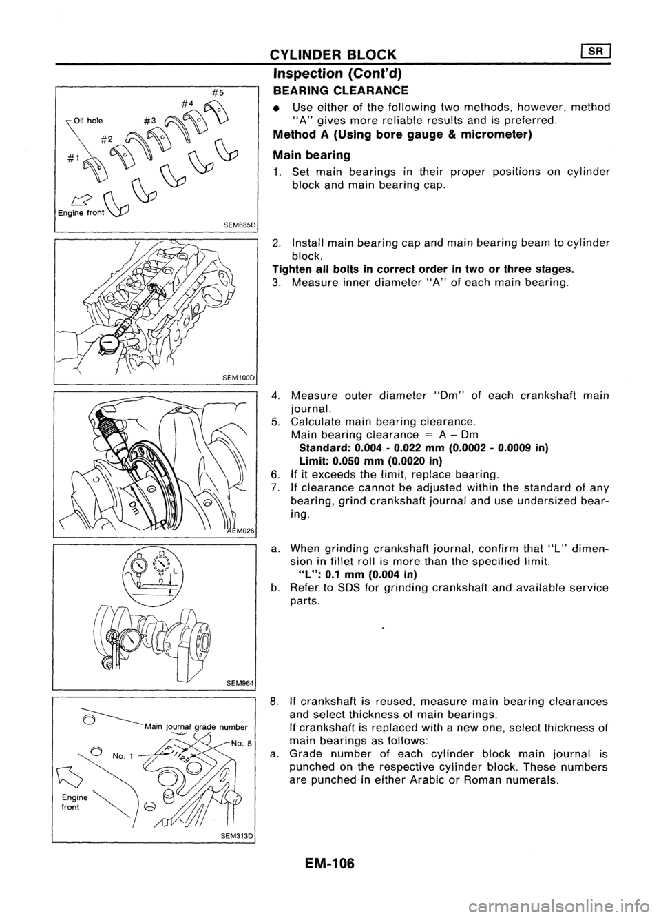
Main bearing
1. Set main bearings intheir proper positions oncylinder
block andmain bearing cap.
2. Install mainbearing capand main bearing beamtocylinder
block.
Tighten allbolts incorrect orderintwo orthree stages.
3. Measure innerdiameter "A"ofeach main bearing.
4. Measure outerdiameter "Om"ofeach crankshaft main
journal.
5. Calculate mainbearing clearance.
Main bearing clearance
=
A-Om
Standard: 0.004•0.022 mm(0.0002 •0.0009 in)
Limit: 0.050mm(0.0020 in)
6. Ifitexceeds thelimit, replace bearing.
7. Ifclearance cannotbeadjusted withinthestandard ofany
bearing, grindcrankshaft journalanduseundersized bear-
ing.
a. When grinding crankshaft journal,confirmthat"L"dimen-
sion infillet rollismore thanthespecified limit.
"L":
0.1mm (0.004 in)
b. Refer toSOS forgrinding crankshaft andavailable service
parts.
8. Ifcrankshaft isreused, measure mainbearing clearances
and select thickness ofmain bearings.
If crankshaft isreplaced withanew one, select thickness of
main bearings asfollows:
a. Grade number ofeach cylinder blockmainjournal is
punched onthe respective cylinderblock.These numbers
are punched ineither Arabic orRoman numerals.
EM-106
Page 1286 of 1701
Crankshaft
front view
Crankshaft
front view
•
Crankshaft
Cylinderblockmainjournal gradenumber
main journal
grade num-
0 12
3
ber
012
3
0
(A,Black) (B,
Brown) (C,
Green) (0,Yellow)
.
12
3
4
1
(B,Brown) (C,Green) (0,
Yellow) (E,Blue)
2
3
4
5
2
(C,Green) (0,
Yellow) (E,Blue) (F,Pink)
3
4
5
6
3
(0,Yellow) (E,
Blue) (F,
Pink) (G,Nocolor)
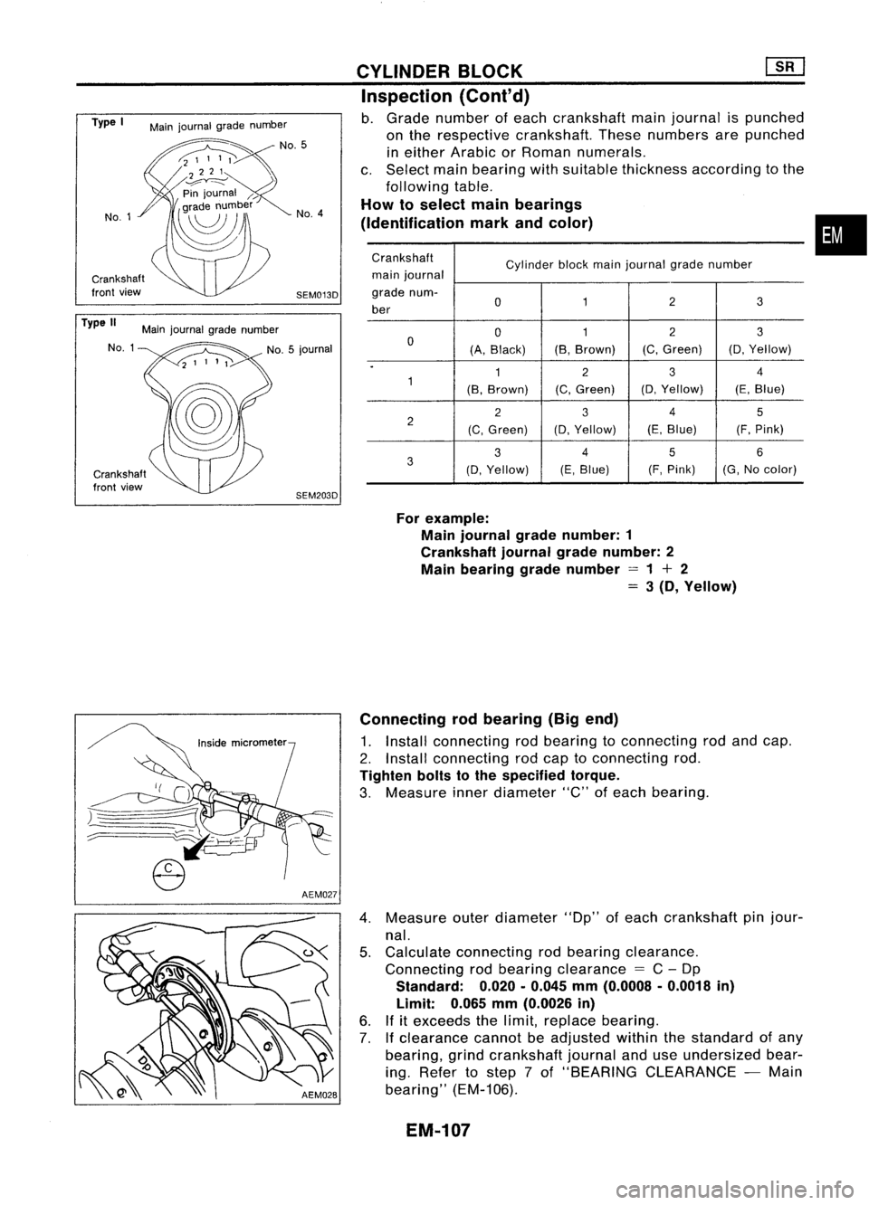
For example:
Main journal gradenumber: 1
Crankshaft journalgradenumber: 2
Main bearing gradenumber =1+ 2
=
3(D, Yellow)
CYLINDER
BLOCK ~
Inspection (Conl'd)
b. Grade number ofeach crankshaft mainjournal ispunched
on the respective crankshaft. Thesenumbers arepunched
in either Arabic orRoman numerals.
c. Select mainbearing withsuitable thickness according tothe
following table.
How toselect mainbearings
(Identification markandcolor)
SEM013D No.
4
SEM203D
Main
journal gradenumber
No.5
Main journal gradenumber
NO.1
Type
I
No.1
Type II
Connectingrodbearing (Bigend)
1. Install connecting rodbearing toconnecting rodand cap.
2. Install connecting rodcap toconnecting rod.
Tighten boltstothe specified torque.
3. Measure innerdiameter "C"ofeach bearing.
4. Measure outerdiameter "Dp"ofeach crankshaft pinjour-
nal.
5. Calculate connecting rodbearing clearance.
Connecting rodbearing clearance
=
C-Dp
Standard:
0.020.0.045
mm
(0.0008 .0.0018
in)
Limit:
0.065
mm
(0.0026
in)
6. Ifitexceeds thelimit, replace bearing.
7.
If
clearance cannotbeadjusted withinthestandard ofany
bearing, grindcrankshaft journalanduseundersized bear-
ing. Refer tostep 7of "BEARING CLEARANCE -Main
bearing" (EM-106).
EM-107
Page 1287 of 1701
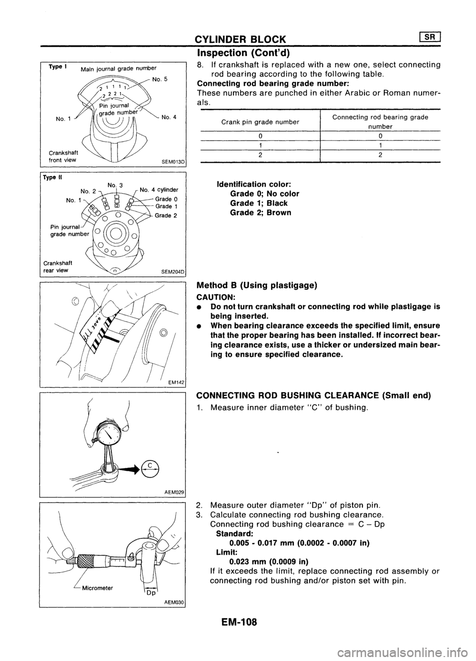
Connectingrodbearing grade
number
o
1
2
o
1
2
Crank
pingrade number
Identification color:
Grade 0;No color
Grade 1;Black
Grade 2;Brown
Method B(Using plastigage)
CAUTION: • Donot turn crankshaft orconnecting rodwhile plastigage is
being inserted.
• When bearing clearance exceedsthespecified limit,ensure
that theproper bearing hasbeen installed.
If
incorrect bear-
ing clearance exists,useathicker orundersized mainbear-
ing toensure specified clearance.
CONNECTING RODBUSHING CLEARANCE (Smallend)
1. Measure innerdiameter "C"ofbushing.
CYLINDER
BLOCK ~
Inspection (Cont'd)
8. Ifcrankshaft isreplaced withanew one, select connecting
rod bearing according tothe following table.
Connecting rodbearing gradenumber:
These numbers arepunched ineither Arabic orRoman numer-
als.
AEM029
SEM013D
No.
4
SEM204D
No.
4cylinder
Grade 0
Grade 1
Grade 2
No.
3
Main
journal gradenumber
No.1
Crankshaft
front view
Type
I
Crankshaft rear view
Type
II
2.Measure outerdiameter "Dp"ofpiston pin.
3. Calculate connecting rodbushing clearance.
Connecting rodbushing clearance
=
C-Dp
Standard: 0.005 -0.017 mm(0.0002 -0.0007 in)
Limit: 0.023 mm(0.0009 in)
If
itexceeds thelimit, replace connecting rodassembly or
connecting rodbushing and/orpistonsetwith pin.
AEM030
EM-108
Page 1289 of 1701
Frontmark
Oil hole
Engine
front Piston
grade
number
Cylindernumber
SEM946C
Top
Oil
SEM199F CYLINDER
BLOCK []:[J
Assembly (Conl'd)
2. Heat piston to60 to70°C (140to158°F) andassemble piston,
piston pin,connecting rodand new snap ring.
• Align thedirection ofpiston andconnecting rod.
• Numbers stampedonconnecting rodand capcorrespond to
each cylinder.
• After assembly, makesureconnecting rodswings
smoothly.
3. Set piston ringsasshown.
CAUTION:
• When piston ringsarenotreplaced, makesurethatpiston
rings aremounted intheir original positions.
• When replacing pistonrings,thosewithout punchmarks can
be mounted witheither sideup.
Oil ring
expander
*v
Engine!/
front
(:J
#5
#4 ~
~il hole #3~~ \)
#2 ~~ ,
#1~~~ ~~
12 ~~
Engine front~
SEM685DCRANKSHAFT
1. Set main bearings intheir proper positions oncylinder
block andmain bearing cap.
• Confirm thatcorrect mainbearings areused. Referto
"Inspection" ofthis section.
• Apply newengine oiltobearing surfaces.
EM-110
Page 1290 of 1701
![NISSAN ALMERA N15 1995 Service Manual Tighteninnumerical order.
'::::::-.... Alignoilhole.
~~
'~~-
SEM015D
SEM159B CYLINDER
BLOCK [][]
Assembly (Cont'd)
2. Install crankshaft andmain bearing capsandtighten bolts
to the spec NISSAN ALMERA N15 1995 Service Manual Tighteninnumerical order.
'::::::-.... Alignoilhole.
~~
'~~-
SEM015D
SEM159B CYLINDER
BLOCK [][]
Assembly (Cont'd)
2. Install crankshaft andmain bearing capsandtighten bolts
to the spec](/manual-img/5/57349/w960_57349-1289.png)
Tighteninnumerical order.
'::::::-.... Alignoilhole.
~~
'~~-
SEM015D
SEM159B CYLINDER
BLOCK [][]
Assembly (Cont'd)
2. Install crankshaft andmain bearing capsandtighten bolts
to the specified torque.
• Apply newengine oiltothread ofbearing capbolts.
• Prior totightening bearingcapbolts, shiftcrankshaft back
and forth toproperly seatthebearing cap.
• Tightening procedure
a. Tighten allbolts to26 to32 N'm (2.7to3.3 kg-m, 20to24 •
in-Ib).
b. Turn allbolts 75to80 degrees clockwise withTool orsuit-
able angle wrench.
c. Loosen allbolts completely.
d. Tighten allbolts to32 to38 N'm (3.3to3.9 kg-m, 24to28
ft-Ib).
e. Turn allbolts 45to50 degrees clockwise withTool orsuit-
able angle wrench.
• Ifan angle wrench isnot available, markallbearing cap
bolts onthe side facing engine rear.Then, turneach bolt
specified degreesclockwise. Confirmangleofdegrees with
a graduator, notbyeye-measurement.
• After securing bearingcapbolts, makesurecrankshaft
turns smoothly byhand.
3. Measure crankshaft endplay.
Crankshaft endplay:
Standard
0.10 -0.26 mm(0.0039 -0.0102 in)
Limit
0.30 mm(0.0118 in)
If beyond thelimit, replace thrustbearings withnewones.
4. Install connecting rodbearings inconnecting rodsandcon-
necting rodcaps.
• Confirm thatcorrect bearings areused. Referto
"I nspection" .
• Install bearings sothat oilhole inconnecting rodaligns with
oil hole ofbearing.
• Apply newengine oiltobolt threads andbearing surfaces.
5. Install pistons withconnecting rods.
a. Install themintocorresponding cylinderswithTool.
• Becareful nottoscratch cylinder wallbyconnecting rod.
• Arrange sothat front mark onpiston headfaces toward
front ofengine.
• Apply newengine oiltopiston ringsandsliding surface of
piston.
EM-111
Page 1303 of 1701
![NISSAN ALMERA N15 1995 Service Manual TIMINGBELT
@[]
Camshaft TimingBelt(Cont'd)
5. Install timing beltwith crankshaft sprocket.
a. Align white linesontiming beltwith punchmarks oncam-
shaft sprocket andcrankshaft sprocket.
b. Poi NISSAN ALMERA N15 1995 Service Manual TIMINGBELT
@[]
Camshaft TimingBelt(Cont'd)
5. Install timing beltwith crankshaft sprocket.
a. Align white linesontiming beltwith punchmarks oncam-
shaft sprocket andcrankshaft sprocket.
b. Poi](/manual-img/5/57349/w960_57349-1302.png)
TIMINGBELT
@[]
Camshaft TimingBelt(Cont'd)
5. Install timing beltwith crankshaft sprocket.
a. Align white linesontiming beltwith punchmarks oncam-
shaft sprocket andcrankshaft sprocket.
b. Point arrow ontiming belttoward beltcover.
6. Install camshaft sprocketplateandsecure screws withlock-
tite.
7. Adjust timing belttension.
1) Loosen tensioner lockbolttoapply tension totiming belt.
2) Rotate crankshaft clockwisetwoturns toapply thespecified
tension totiming belt.
3) Tighten tensioner lockboltwhile holding tensioner pUlley
with hexagon wrench. .
Belt tension:
147.1 :1:24.5 N(15:1:2.5 kg,33.1 :1:5.5 Ib)
SEM520D Injection PumpTiming Belt
~ .N'm (kg-m, in-Ib)
~ :N.m (kg-m, ft-Ib)
SEC.
130-135
~
-"~
.~\(~[-~~' c~1
Timingbelt
?\~-d
(~K.
c
'0
t£
Tensioner spring
J
J
N
0~lJ'00 ~/ Tensioner
t0
J
l\J~.~l:~
'Gl
~')U
r
r~/~
16-21 (1.6 -2.1,12 -15)
It
I
L~0--~ '
~htiJ
JD/~h~J/ "
'SP/
_-z,}) ~A
[/ ......., ....... InJeclion~
.... ~. -;;, pump@J_
• '~~ sprocket~
"fc;,~~-
@ ~
59-
69-.1
Rear camshaft sprocket .~(6.0•7.0,
1m
43-51)
[O;l
87•107
(8.9 -10.9, 64•79)
SEM225F
REMOVAL
1. Set NO.1 cylinder atTDC onitscompression stroke.(TDC
is indicated bycrankshaft pulleynotchwithout painted
mark.)
2. Remove airduct withresonator andtiming beltcover.
EM-124