1995 NISSAN ALMERA N15 ESP
[x] Cancel search: ESPPage 982 of 1701
ON-BOARDDIAGNOSTIC SYSTEMDESCRIPTION
CONSULT (Cont'd)
REAL TIMEDIAGNOSIS INDATA MONITOR MODE
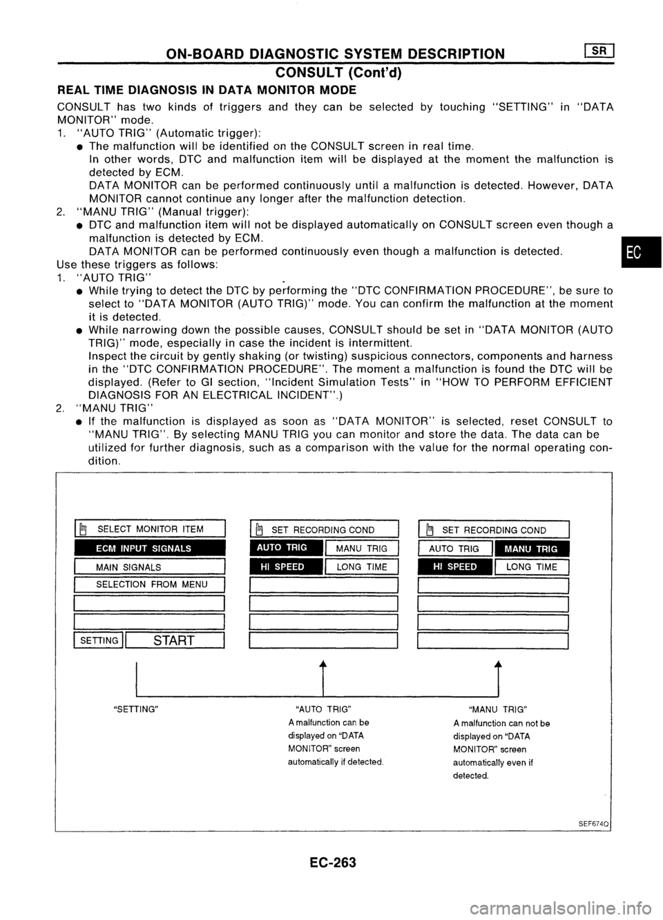
CONSULT hastwo kinds oftriggers andthey canbeselected bytouching "SETTING" in"DATA
MONITOR" mode.
1. "AUTO TRIG"(Automatic trigger):
• The malfunction willbeidentified onthe CONSULT screeninreal time.
In other words, DTCandmalfunction itemwillbedisplayed atthe moment themalfunction is
detected byECM.
DATA MONITOR canbeperformed continuously untilamalfunction isdetected. However, DATA
MONITOR cannotcontinue anylonger afterthemalfunction detection.
2. "MANU TRIG"(Manual trigger):
• DTC andmalfunction itemwillnotbedisplayed automatically onCONSULT screeneventhough a
malfunction isdetected byECM. •
DATA MONITOR canbeperformed continuously eventhough amalfunction isdetected.
Use these triggers asfollows:
1. "AUTO TRIG"
• While trying todetect theDTC byperforming the"DTC CONFIRMATION PROCEDURE",besure to
select to"DATA MONITOR (AUTOTRIG)" mode.Youcanconfirm themalfunction atthe moment
it is detected .
• While narrowing downthepossible causes,CONSULT shouldbeset in"DATA MONITOR (AUTO
TRIG)" mode,especially incase theincident isintermittent.
Inspect thecircuit bygently shaking (ortwisting) suspicious connectors, components andharness
in the "DTC CONFIRMATION PROCEDURE".Themoment amalfunction isfound theDTC willbe
displayed. (RefertoGI section, "Incident Simulation Tests"in"HOW TOPERFORM EFFICIENT
DIAGNOSIS FORANELECTRICAL INCIDENT".)
2. "MANU TRIG"
• Ifthe malfunction isdisplayed assoon as"DATA MONITOR" isselected, resetCONSULT to
"MANU TRIG".Byselecting MANUTRIGyoucan monitor andstore thedata. Thedata canbe
utilized forfurther diagnosis, suchasacomparison withthevalue forthe normal operating con-
dition.
ECM INPUT SIGNALS
HISPEED
AUTO
TRIG
I
~
SELECT MONITOR ITEM
I
MAIN SIGNALS
I
SELECTION FROMMENU
1 _
1========
l-SE-TI-IN-G
ll--S-T.-AR-T--
I
~
SET RECORDING COND
I
MANU TRIG
I
LONG TIME HI
SPEED MANU
TRIG
__ 1__ J
"SETIING" "AUTOTRIG"
A malfunction canbe
displayed on"DATA
MONITOR" screen
automatically ifdetected.
EC-263 "MANU
TRIG"
A malfunction cannotbe
displayed on"DATA
MONITOR" screen
automatically evenif
detected.
SEF6740
Page 983 of 1701

TROUBLEDIAGNOSIS -General Description
Sensors
~ ECMActuators
~~.~ MEF036D
SEF234G Introduction
The engine hasanECM tocontrol majorsystems suchasfuel
control, ignitioncontrol, idleaircontrol system, etc.The ECM
accepts inputsignals fromsensors andinstantly drivesactua-
tors. Itis essential thatboth input andoutput signals areproper
and stable. Atthe same time,itis important thatthere areno
problems suchasvacuum leaks,fouled sparkplugs, orother
problems withtheengine.
It is much moredifficult todiagnose aproblem thatoccurs
intermittently ratherthancontinuously. Mostintermittent prob-
lems arecaused bypoor electric connections orimproper wir-
ing. Inthis case, careful checking ofsuspected circuitsmay
help prevent thereplacement ofgood parts.
A visual checkonlymaynotfind thecause ofthe problems. A
road testwith CONSULT oracircuit testerconnected shouldbe
performed. Followthe"Work Flow"onthe next page.
Before undertaking actualchecks, takejustafew minutes to
talk with acustomer whoapproaches withadriveability com-
plaint. Thecustomer cansupply goodinformation aboutsuch
problems, especially intermittent ones.Findoutwhat symptoms
are present andunder whatconditions theyoccur. A"Diagnos-
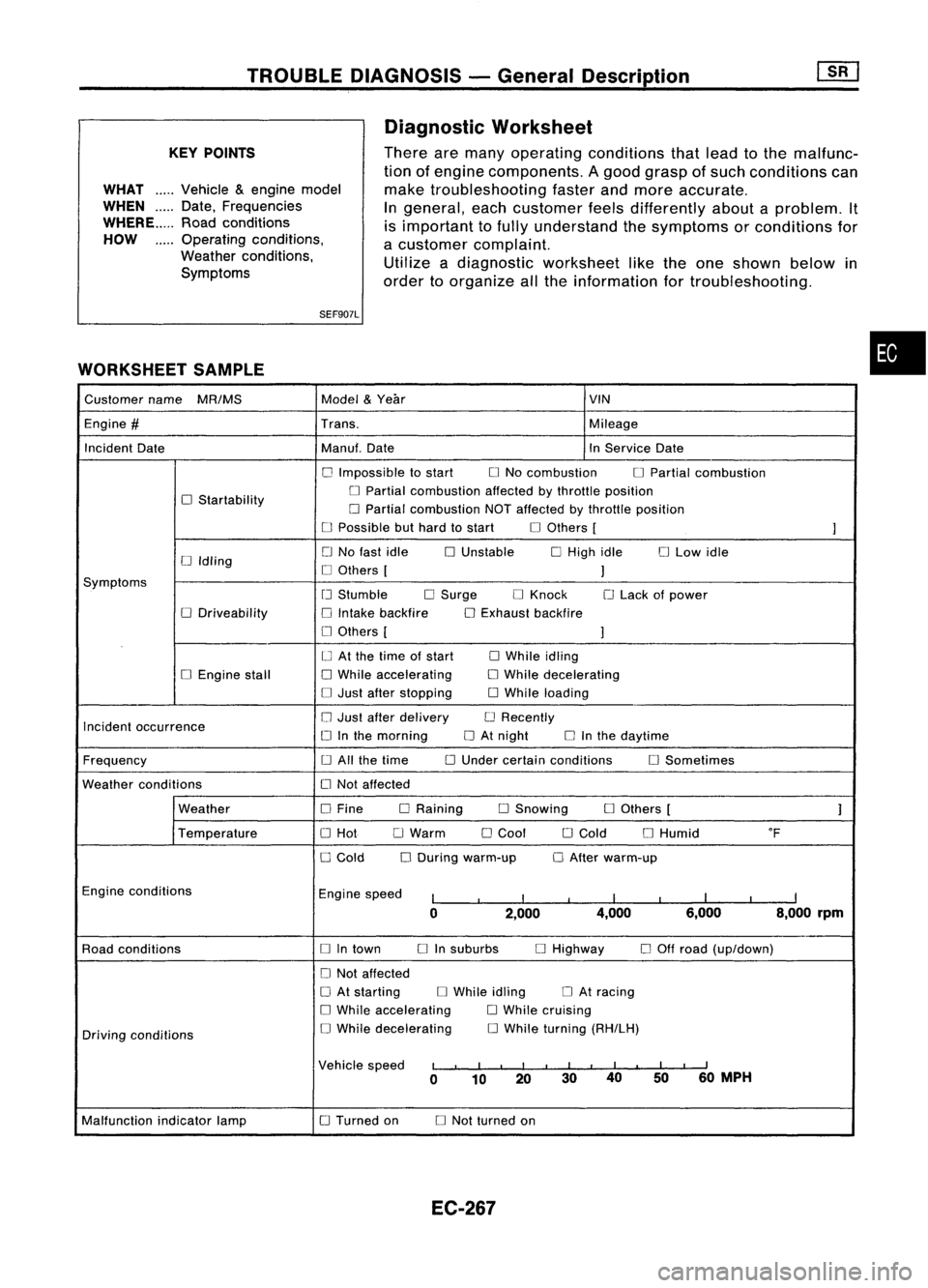
tic Worksheet" liketheexample onEC-267 shouldbeused.
Start yourdiagnosis bylooking for"conventional" problems
first. Thiswillhelp troubleshoot driveabilityproblemsonan
electronically controlledenginevehicle.
EC-264
Page 986 of 1701
TROUBLEDIAGNOSIS -General Description
KEY POINTS
WHAT .....
Vehicle &engine model
WHEN
Date,Frequencies
WHERE Roadconditions
HOW Operatingconditions,
Weather conditions,
Symptoms
SEF907L
WORKSHEET SAMPLE Diagnostic
Worksheet
There aremany operating conditions thatlead tothe malfunc-
tion ofengine components. Agood grasp ofsuch conditions can
make troubleshooting fasterandmore accurate.
In
general, eachcustomer feelsdifferently aboutaproblem. It
is important tofully understand thesymptoms orconditions for
a customer complaint.
Utilize adiagnostic worksheet liketheone shown belowin
order toorganize allthe information fortroubleshooting.
•
Customer name
MR/MS Model
&
Year VIN
Engine
#
Trans. Mileage
Incident Date Manuf.Date InService Date
o
Impossible tostart
o
No combustion
o
Partial combustion
o
Startability
o
Partial combustion affectedbythrottle position
o
Partial combustion NOTaffected bythrottle position
o
Possible buthard tostart
o
Others [
]
o
No fast idle
o
Unstable
o
High idle
o
Low idle
[J
Idling
o
Others [
]
Symptoms
[J
Stumble
o
Surge
o
Knock
o
Lack ofpower
o
Driveability
o
Intake backfire
o
Exhaust backfire
o
Others [
]
o
At the time ofstart
o
While idling
o
Engine stall
o
While accelerating
o
While decelerating
o
Just after stopping
o
While loading
Incident occurrence
o
Just after delivery
o
Recently
o
Inthe morning
o
At night
o
Inthe daytime
Frequency
o
All the time
o
Under certain conditions
o
Sometimes
Weather conditions
o
Not affected
Weather
o
Fine DRaining
o
Snowing
o
Others [
]
Temperature
o
Hot
o
Warm
o
Cool
o
Cold
o
Humid
of
o
Cold
o
During warm-up
o
After warm-up
Engine conditions
Enginespeed
I
I
I
I
I
I
I
I
I
0 2,000 4,000
6,000 8,000rpm
Road conditions
o
Intown
o
Insuburbs
o
Highway
o
Off road (up/down)
o
Not affected
o
At starting
o
While idling
o
At racing
o
While accelerating
o
While cruising
Driving conditions
o
While decelerating
o
While turning (RH/LH)
Vehicle speed
I
I
I
I
I
I
II
I
I
I
II
0 10 20 3040
5060
MPH
Malfunction indicatorlamp
o
Turned on
o
Not turned on
EC-267
Page 987 of 1701
TROUBLEDIAGNOSIS -General Description
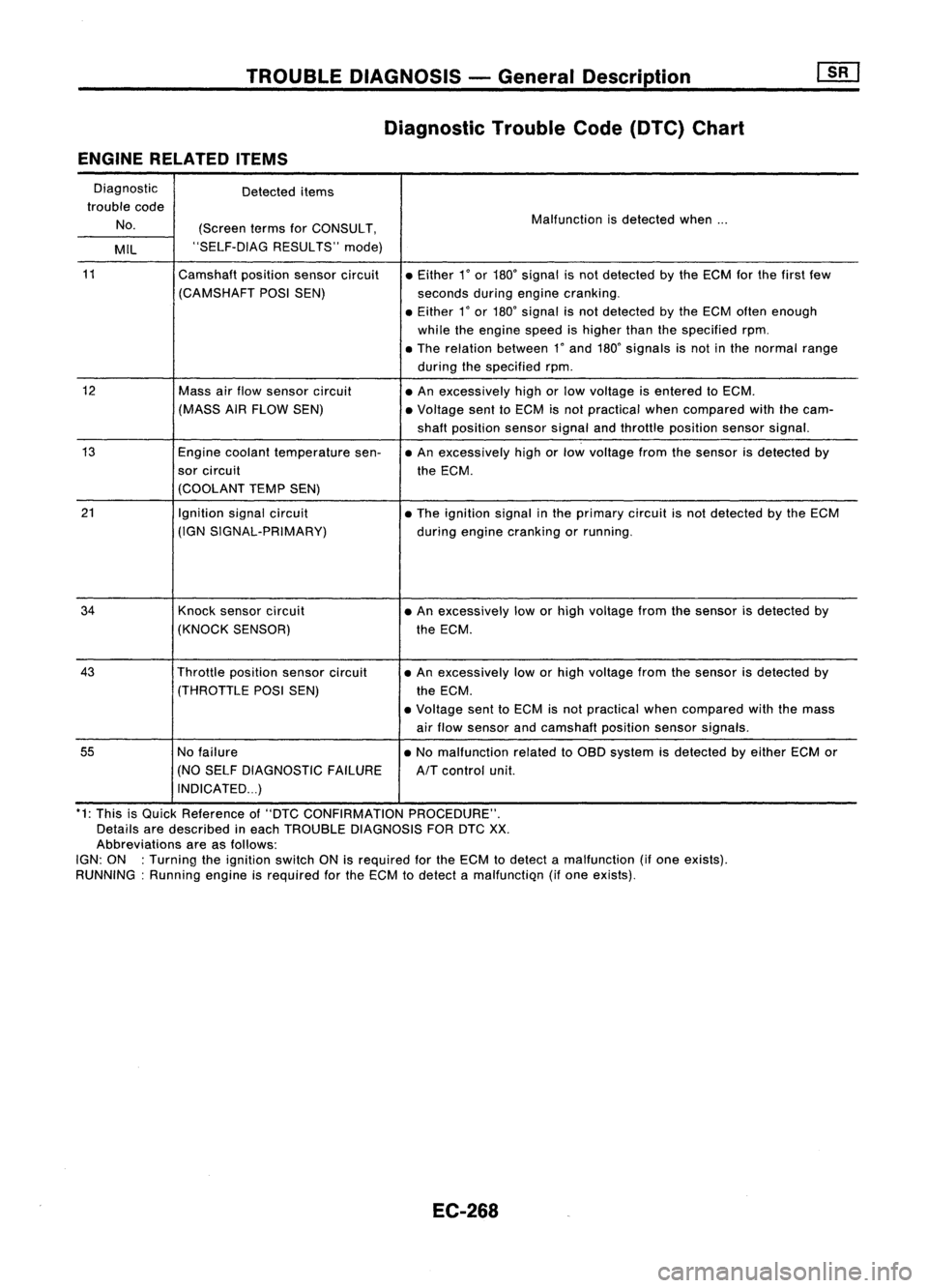
Diagnostic TroubleCode(DTC) Chart
ENGINE RELATED ITEMS
Diagnostic Detecteditems
trouble code
No. (ScreentermsforCONSULT, Malfunction
isdetected when...
MIL "SELF-DIAG
RESULTS"mode)
11
Camshaftpositionsensorcircuit •Either
1
0
or
180
0
signal isnot detected bythe ECM forthe first few
(CAMSHAFT POSISEN) secondsduringengine cranking .
• Either
1
0
or
180
0
signal isnot detected bythe ECM often enough
while theengine speedishigher thanthespecified rpm.
• The relation between
1"
and
180"
signals isnot inthe normal range
during thespecified rpm.
12
Massairflow sensor circuit
•An excessively highorlow voltage isentered toECM.
(MASS AIRFLOW SEN) •Voltage senttoECM isnot practical whencompared withthecam-
shaft position sensorsignalandthrottle position sensorsignal.
13
Enginecoolant temperature sen-•An excessively highorlow voltage fromthesensor isdetected by
sor circuit theECM.
(COOLANT TEMPSEN)
21
Ignitionsignalcircuit
•The ignition signalinthe primary circuitisnot detected bythe ECM
(IGN SIGNAL-PRIMARY)
duringengine cranking orrunning.
34
Knocksensor circuit •An excessively loworhigh voltage fromthesensor isdetected by
(KNOCK SENSOR) theECM .
43
Throttlepositionsensorcircuit •
An excessively loworhigh voltage fromthesensor isdetected by
(THROTTLE POSISEN)
theECM.
• Voltage senttoECM isnot practical whencompared withthemass
air flow sensor andcamshaft positionsensorsignals.
55
Nofailure •No malfunction relatedtoOBD system isdetected byeither ECMor
(NO SELF DIAGNOSTIC FAILURE
AIT
control unit.
INDICATED ...)
*1: This isQuick Reference of"DTC CONFIRMATION PROCEDURE".
Details aredescribed ineach TROUBLE DIAGNOSIS FORDTC
XX.
Abbreviations areasfollows:
IGN: ON :Turning theignition switchONisrequired forthe ECM todetect amalfunction (ifone exists).
RUNNING: Runningengineisrequired forthe ECM todetect amalfunctiQn (ifone eXists).
EC-268
Page 989 of 1701
TROUBLEDIAGNOSIS -General Description
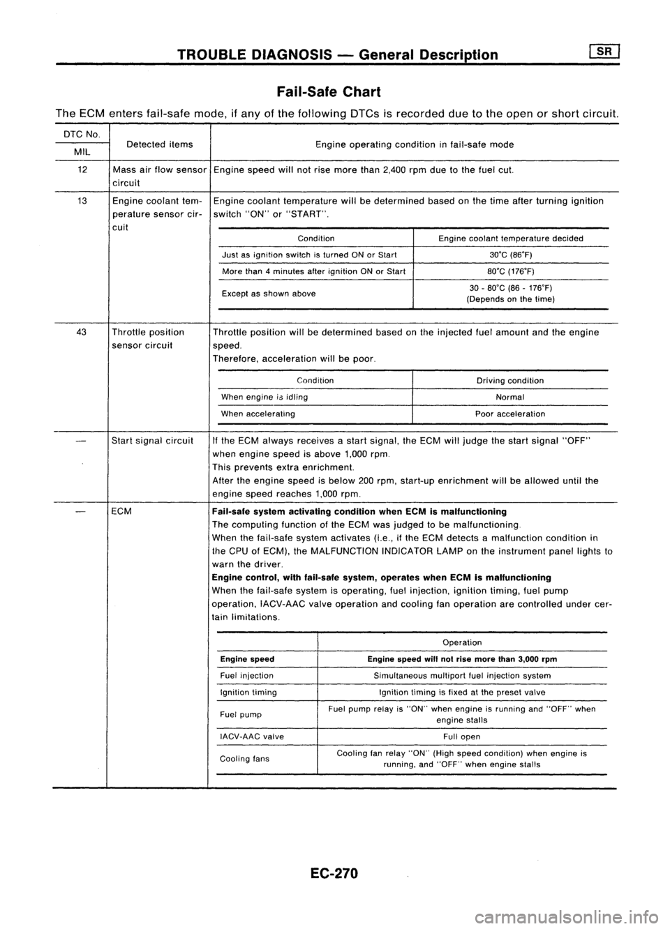
Fail-Safe Chart
The ECM enters fail-safe mode,ifany ofthe following DTCsisrecorded duetothe open orshort circuit.
DTC No.
Detected items Engineoperating conditioninfail-safe mode
MIL
12 Massairflow sensor Enginespeedwillnotrise more than2,400 rpmduetothe fuel cut.
circuit
13 Enginecoolant tem-Engine coolant temperature willbedetermined basedonthe time after turning ignition
perature sensorcir-switch "ON"or"START".
cuit ConditionEnginecoolant temperature decided
Just asignition switchisturned ONorStart 30'C(86'F)
More than4minutes afterignition ONorStart 80'C(176'F)
Except asshown above 30
-80'C (86-176'F)
(Depends onthe time)
43 Throttle position
Throttleposition willbedetermined basedonthe injected fuelamount andtheengine
sensor circuit
speed.
Therefore, acceleration willbepoor.
Condition Drivingcondition
When engine i$idling
Normal
When accelerating Pooracceleration
-
Start
signal circuit
If
the ECM always receives astart signal, theECM willjudge thestart signal "OFF"
when engine speedisabove 1,000rpm.
This prevents extraenrichment.
After theengine speedisbelow 200rpm, start-up enrichment willbeallowed untilthe
engine speedreaches 1,000rpm.
-
ECM
Fail-safesystemactivating conditionwhenECMismalfunctioning
The computing functionofthe ECM wasjudged tobe malfunctioning.
When thefail-safe systemactivates (i.e.,ifthe ECM detects amalfunction conditionin
the CPU ofECM), theMALFUNCTION INDICATORLAMPonthe instrument panellightsto
warn thedriver.
Engine control, withfail-safe system,operates whenECMismalfunctioning
When thefail-safe systemisoperating, fuelinjection, ignitiontiming,fuelpump
operation, IACV-AACvalveoperation andcooling fanoperation arecontrolled undercer-
tain limitations.
Operation
Engine speed Enginespeedwillnotrise more than3,000 rpm
Fuel injection
Simultaneousmultiportfuelinjection system
Ignition timing Ignitiontimingisfixed atthe preset valve
Fuel pump Fuel
pump relayis"ON" whenengine isrunning and"OFF" when
engine stalls
IACV-AAC valve
Fullopen
Cooling fans Cooling
fanrelay "ON" (Highspeed condition) whenengine is
running, and"OFF" whenengine stalls
EC-270
Page 992 of 1701
TROUBLEDIAGNOSIS -General Description
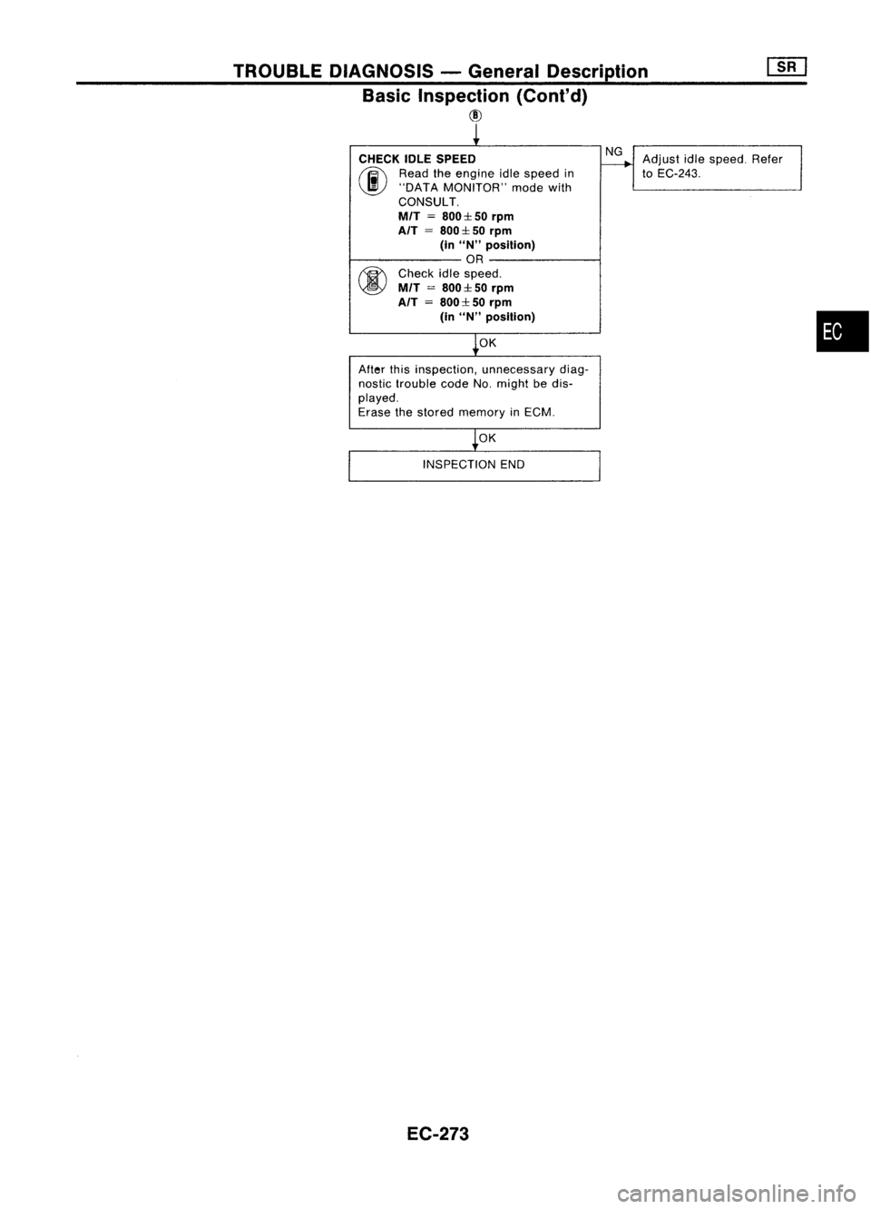
Basic Inspection (Conl'd)
@
CHECK IDLESPEED
(ij\
Readtheengine idlespeed in
~ "DATA MONITOR" modewith
CONSULT.
MfT
=
800:1: 50
rpm
AfT
=
800:1: 50
rpm
(in
uN"
position)
OR
fiY\
Check idlespeed.
~ MfT
=
800:1:50
rpm
AfT =800:1: 50
rpm
(in
uN"
posillon)
OK
After thisinspection, unnecessary diag-
nostic trouble codeNo.might bedis-
played.
Erase thestored memory inECM.
OK
INSPECTION END
EC-273 NG
Adjust idlespeed. Refer
to
EC-243.
•
Page 993 of 1701
TROUBLEDIAGNOSIS -General Description
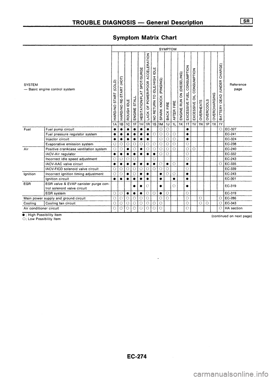
Symptom MatrixChart
SYMPTOM
z
0
i=
0::
Z
ill
w w
w
(!)
(!J
-l
-l
0
Z
0::
W
i=
0
0::
0
Q
(9
c..
i=
::>
0
z
::2:
:r:
i='
l/)
(9
:J
c..
0
6'
0
j::::
Q
::>
::2:
0::
;S
0
0::
:r:
z
w
l/)
::>
w
SYSTEM
....J
0
a
l/)
z
l/)
Reference
0
l-
e..
0
iJJ
w
0
z
0
- Basic engine control system
S?-
l/)
-l
Z
9-
z
0::
c..
Q ~
0
0
2-
page
I-
l-
ii:
....J
0
II:
I-
w
0
z
w
(!)
0
l/)
....J....J
~
:>:::
0
::>
-l
z
uJ
....J
U.
I-
0
U.
(5
B
I-
W
0
z
l/)
w
l/)
II:
....J
Z
0
W
WW
l/)
....J
II:
0
I-
0
c..
II:
Z
W
II:
::>
I-
0
0
Q
l/)
II:II:
>>
i=
u.
::>
:>:::
u::
ii5ii5
w
0
:r:
>-
z z
w
0
I-
u::
W
II:
0 0
:r:
z
w
:>:::
II:
z
l/)
l/)
:r:
0 0
w
(!J
I-
:>:::
II: II:
:>:::
~
w
W
II:
II: II:
r:
II:
II:
::>
B
ii5
0
B
00
w
w w
z
w
c..
Z
><><
>
> >
:r: :r:
II:
w
:r:
-l
z
l/)
co
WW
00 0
co
1A 181C 1F1H
1R
1S1M
1J1L1K
1T
1V1N 1P1X 1Y
Fuel Fuelpump circuit
•
•
•
•
•
•
0
0
•
0
EC-327
Fuel pressure regulatorsystem
•
••
•
••
0
0 00
•
EC-241
Injector circuit
••
•
• •
•
0
00
•
EC-324
Evaporative emissionsystem
00 0 00
0 0
0
0
0 0
EC-238
Air Positivecrankcase ventilation system
00
•
0
•
0
0 0
0
0
00
EC-240
IACV-Air regulator
•••
•
••
•
0
0
0
EC-332
Incorrect idlespeed adjustment
0
0
0
0 0 0
EC-243
IACV-AAC valvecircuit
••
•
•
•
•
•
0
•
0
•
0
EC-335
IACV-FICD solenoidvalvecircuit
0
0 0
000 00 0
C)
EC-339
Ignition Incorrectignitiontimingadjustment
00
•
0
•• •
0
0
•
EC-243
Ignition circuit
•
•
•
•
•
•
• •
•
EC-301
EGR EGRvalve
&
EVAP canister purgecon-
00
trol solenoid valvecircuit
•
•
•
•
EC-319
EGR system
0
()
•• •
0
0
•
0
0
EC-319
Main power supply andground circuit
00 0 0
C)
0 00
0
0
0
EC-286
Cooling Coolingfancircuit
0
0
0
00 00 0 000 0
EC-343
Air conditioner circuit
00 00 0
00
0 0
0
HA
section
• ;High Possibility Item
0;
Low Possibility Item
EC-274
(continued
onnext page)
Page 996 of 1701
TROUBLEDIAGNOSIS -General Description
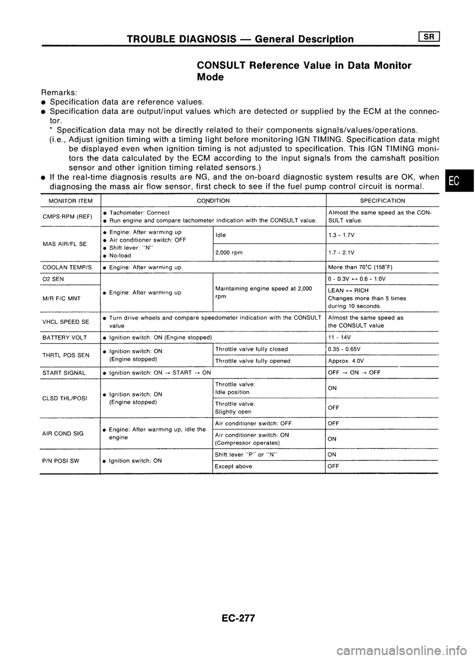
CONSULT Reference ValueinData Monitor
Mode
Remarks:
• Specification dataarereference values.
• Specification dataareoutput/input valueswhicharedetected orsupplied bythe ECM atthe connec-
tor.
*
Specification datamaynotbedirectly relatedtotheir components signals/values/operations.
(Le., Adjust ignition timingwithatiming lightbefore monitoring IGNTIMING. Specification datamight
be displayed evenwhen ignition timingisnot adjusted tospecification. ThisIGNTIMING moni-
tors thedata calculated bythe ECM according tothe input signals fromthecamshaft position
sensor andother ignition timingrelated sensors.)
• Ifthe real-time diagnosis resultsareNG, andtheon-board diagnostic systemresultsareOK, when •
diagnosing themass airflow sensor, firstcheck tosee ifthe fuel pump control circuitisnormal.
MONITOR ITEM CONDITION
SPECIFICATION
CMPS.RPM (REF)•
Tachometer: Connect Almostthesame speed asthe CON-
• Run engine andcompare tachometer indicationwiththeCONSULT value.SULTvalue.
• Engine: Afterwarming up
Idle 1.3-1.7V
MAS AIR/FL SE •
Air conditioner switch:OFF
• Shift lever: "N"
• No-load 2,000
rpm 1.7-2.1V
COOLAN TEMPIS •
Engine: Afterwarming up More
than70°C (15S0F)
02 SEN 0-
0.3V .....0.6 -1.0V
• Engine: Afterwarming up Maintaining
enginespeedat2,000
LEAN
+-->
RICH
MIR
FIC
MNT rpm
Changesmorethan5times
during 10seconds.
VHCL SPEED SE•
Turn drive wheels andcompare speedometer indicationwiththeCONSULT Almostthesame speed as
value the
CONSULT value
BATTERY VOLT •
Ignition switch:ON(Engine stopped) 11
-14V
• Ignition switch:ON Throttle
valvefullyclosed
0.35-0.65V
THRTL
pas
SEN
(Enginestopped)
Throttlevalvefullyopened Approx.4.0V
START SIGNAL •
Ignition switch:ON
->
START
->
ON OFF
->
ON
->
OFF
Throttle valve:
ON
• Ignition switch:ON Idle
position
CLSD THLIPOSI
(Enginestopped)
Throttlevalve:
Slightly open OFF
Air conditioner switch:OFF OFF
AIR COND SIG •
Engine: Afterwarming up,idle the
engine Air
conditioner switch:ON
ON
(Compressor operates)
Shift lever "P"or"N" ON
PIN POSI SW •
Ignition switch:ON
Exceptabove OFF
EC-277