1995 NISSAN ALMERA N15 ESP
[x] Cancel search: ESPPage 1638 of 1701
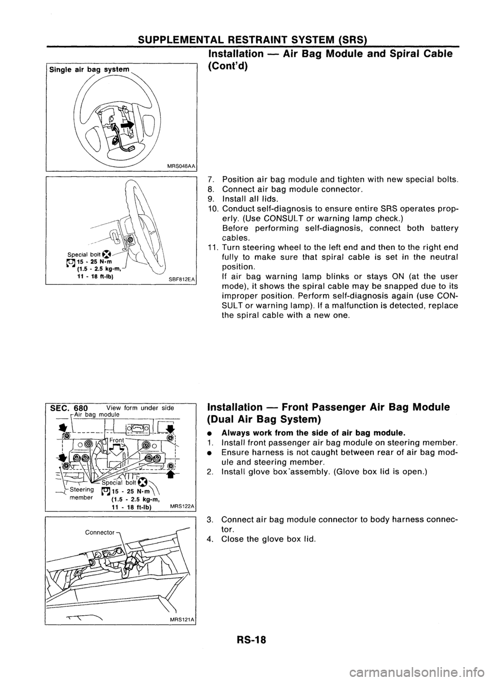
7.Position airbag module andtighten withnewspecial bolts.
8. Connect airbag module connector.
9. Install alllids.
10. Conduct self-diagnosis toensure entireSRSoperates prop-
erly. (Use CONSULT orwarning lampcheck.)
Before performing self-diagnosis, connectbothbattery
cables.
11. Turn steering wheeltothe leftend andthen tothe right end
fully tomake surethatspiral cableisset inthe neutral
position.
If air bag warning lampblinks orstays ON(atthe user
mode), itshows thespiral cablemaybesnapped duetoits
improper position.Performself-diagnosis again(useCON-
SUL Tor warning lamp).Ifa malfunction isdetected, replace
the spiral cablewithanew one.
SBF812EA
MRS046AA
SUPPLEMENTAL
RESTRAINTSYSTEM(SRS)
Installation -Air Bag Module andSpiral Cable
(Cont'd)
G\\
--------~
~\)
..~l~~
\\\?\\
Special bolt~~ "'(\\
cc:J
15-25 N.m ~
(1.5 -2.5 kg-m,
11 -18 ft-Ibl
Installation-Front Passenger AirBag Module
(Dual AirBag System)
• Always workfromtheside ofair bag module.
1. Install frontpassenger airbag module onsteering member.
• Ensure harness isnot caught between rearofair bag mod-
ule and steering member.
2. Install glovebox'assembly. (Gloveboxlidisopen.)
3. Connect airbag module connector tobody harness connec-
tor.
4. Close theglove boxlid.
RS-18
Page 1639 of 1701
SUPPLEMENTALRESTRAINTSYSTEM(SRS)
Disposal ofAir Bag Module andSeat Belt
Pre-tensioner
• Before disposing ofair bag module andseat beltpre-tensioner, orvehicles equipped withsuch
systems, deploythesystems. Ifsuch systems havealready beendeployed duetoan accident, dis-
pose ofas indicated in"DISPOSING OFAIR BAG MODULE ANDSEAT BELTPRE-TENSIONER" (RS-
24).
• When deploying theairbag module, alwaysusetheSpecial Service Tool;Deployment tool
KV99106400.
• When deploying theairbag module andseat beltpre-tensioner, standatleast 5m (16 ft)away from
the deployment component.
• Due toheat, leave airbag module unattended formore than30minutes afterdeployment. Alsoleave
seat beltpre-tensioner unattendedformore than10minutes afterdeployment.
• Besure towear gloves whenhandling adeployed airbag module andseat beltpre-tensioner.
• Never applywater toadeployed airbag module.
• Wash yourhands cleanafterfinishing- work.
• Donot dispose ofthe airbag module andseat beltpre-tensioner un-deployed.
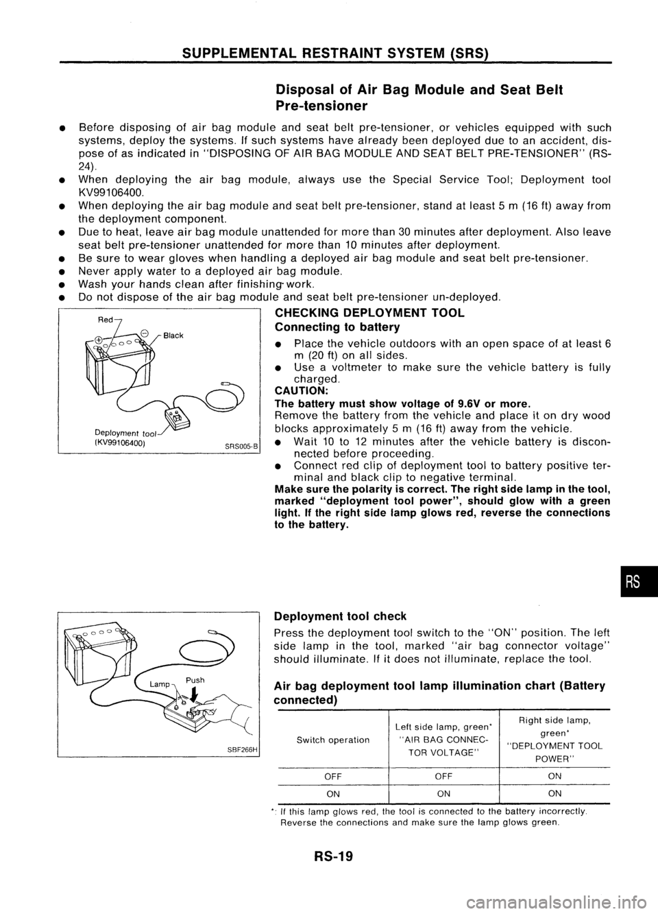
CHECKING DEPLOYMENT TOOL
Connecting tobattery
• Place thevehicle outdoors withanopen space ofat least 6
m (20
ft)
on allsides.
• Use avoltmeter tomake surethevehicle batteryisfully
charged.
CAUTION:
The battery mustshow voltage of9.6V ormore.
Remove thebattery fromthevehicle andplace iton dry wood
Deployment
tool blocksapproximately 5m (16 ft)away fromthevehicle.
(KV99106400j SRS005-B•
Wait 10to12 minutes afterthevehicle batteryisdiscon-
nected beforeproceeding.
• Connect redclip ofdeployment tooltobattery positive ter-
minal andblack cliptonegative terminal.
Make surethepolarity iscorrect. Theright sidelamp inthe tool,
marked "deployment toolpower", shouldglowwithagreen
light. Ifthe right sidelamp glows red,reverse theconnections
to the battery.
•
SBF266H Deployment
toolcheck
Press thedeployment toolswitch tothe "ON" position. Theleft
side lamp inthe tool, marked "airbagconnector voltage"
should illuminate.
If
it
does notilluminate, replacethetool.
Air bag deployment toollamp illumination chart(Battery
connected)
Leftside lamp, green' RighI
sidelamp,
Switch operation "AIR
BAGCONNEC- green'
"DEPLOYMENT TOOL
TOR VOLTAGE"
POWER"
OFF OFF ON
ON ON
ON
,. Ifthis lamp glows red,the1001 isconnecled tothe battery incorrectly.
Reverse theconnections andmake surethelamp glows green.
RS-19
Page 1654 of 1701
•SELF-DIAG RESULTS.
0
FAILURE DETECTED
• NO SELF DIAGNOSTIC
FAILURE INDICATED.
TROUBLE
DIAGNOSES -Supplemental RestraintSystem(SRS)-
Dual AirBag System
Self-diagnosis (Cont'd)
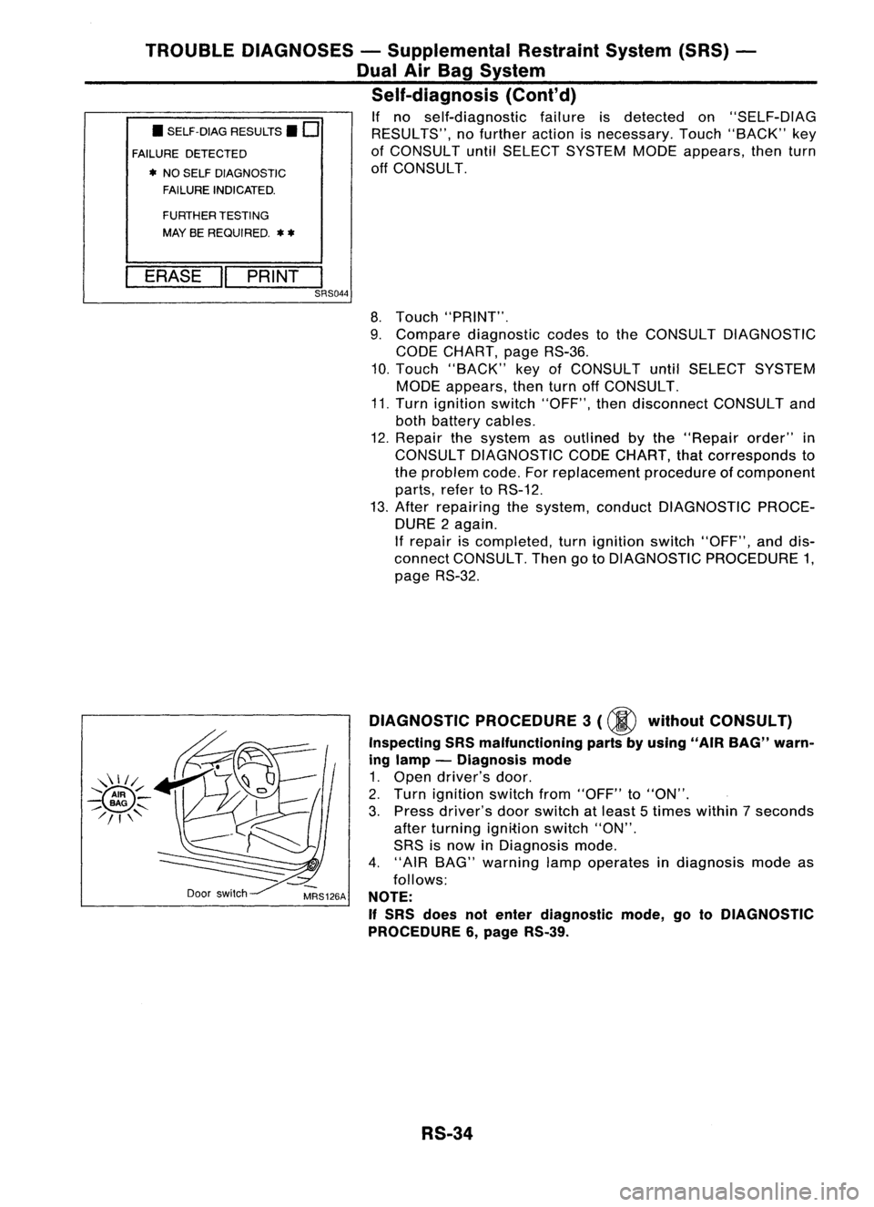
If no self-diagnostic failureisdetected on"SELF-DIAG
RESULTS", nofurther actionisnecessary. Touch"BACK" key
of CONSULT untilSELECT SYSTEM MODEappears, thenturn
off CONSULT.
FURTHER TESTING
MAY BEREQUIRED.
**
ERASE "PRINT
I
SRS044
8.Touch "PRINT".
9. Compare diagnostic codestothe CONSULT DIAGNOSTIC
CODE CHART, pageRS-36.
10. Touch "BACK" keyofCONSULT untilSELECT SYSTEM
MODE appears, thenturnoffCONSULT.
11. Turn ignition switch"OFF", thendisconnect CONSULTand
both battery cables.
12. Repair thesystem asoutlined bythe "Repair order"in
CONSULT DIAGNOSTIC CODECHART, thatcorresponds to
the problem code.Forreplacement procedureofcomponent
parts, refertoRS-12.
13. After repairing thesystem, conduct DIAGNOSTIC PROCE-
DURE 2again.
If repair iscompleted, turnignition switch"OFF", anddis-
connect CONSULT. ThengotoDIAGNOSTIC PROCEDURE 1,
page RS-32.
Door switch DIAGNOSTIC
PROCEDURE 3
(00
without CONSULT)
Inspecting SRSmalfunctioning partsbyusing "AIRBAG" warn-
ing lamp -Diagnosis mode
1. Open driver's door.
2. Turn ignition switchfrom"OFF" to"ON".
3. Press driver's doorswitch atleast 5times within 7seconds
after turning ignition switch"ON".
SRS isnow inDiagnosis mode.
4. "AIR BAG" warning lampoperates indiagnosis modeas
follows:
NOTE:
If
SRS does notenter diagnostic mode,gotoDIAGNOSTIC
PROCEDURE 6,page RS-39.
RS-34
Page 1655 of 1701
TROUBLEDIAGNOSES -Supplemental RestraintSystem(SRS)-
Dual AirBag System
Self-diagnosis (Cont'd)
No.
ON
OFF
IGN
ON
t
"AIR
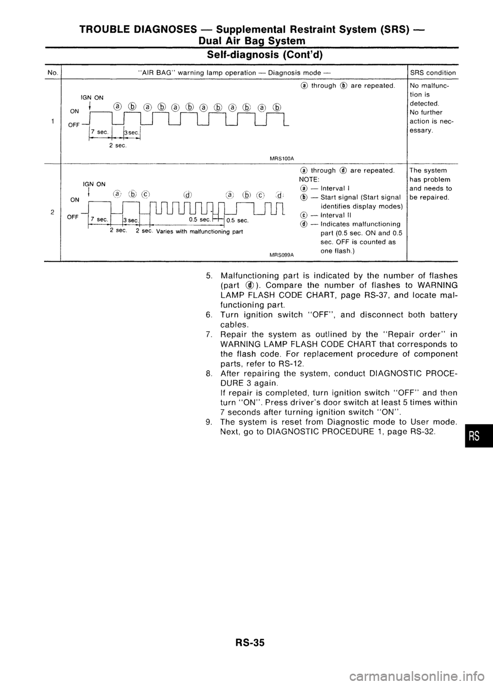
BAG" warning lampoperation -Diagnosis mode-
@
through
@
are repeated.
MRS100A
SRS
condition
No malfunc-
tion is
detected. No further
action isnec-
essary.
2 ON
OFF
IGN
ON
I
7 sec.
@)
@
(c)
3sec.
2 sec. 2sec. Varies withmalfunctioning part
MRS099A
@
through
@
are repeated.
NOTE: @ -
Interval I
@ -
Start signal (Startsignal
identifies displaymodes)
@ -
Interval II
@ -
Indicates malfunctioning
part (0.5sec. ONand 0.5
sec. OFF iscounted as
one flash.) The
system
has problem
and needs to
be repaired.
5. Malfunctioning partisindicated bythe number offlashes
(part
@).
Compare thenumber offlashes toWARNING
LAMP FLASH CODECHART, pageRS-37, andlocate mal-
functioning part.
6. Turn ignition switch"OFF", anddisconnect bothbattery
cables.
7. Repair thesystem asoutlined bythe "Repair order"in
WARNING LAMPFLASH CODECHART thatcorresponds to
the flash code. Forreplacement procedureofcomponent
parts, refertoRS-12.
8. After repairing thesystem, conduct DIAGNOSTIC PROCE-
DURE 3again.
If repair iscompleted, turnignition switch"OFF"andthen
turn "ON". Pressdriver's doorswitch atleast 5times within
7 seconds afterturning ignition switch"ON".
9. The system isreset fromDiagnostic modetoUser mode.
Next, gotoDIAGNOSTIC PROCEDURE 1,page RS-32. •
RS-35
Page 1656 of 1701
TROUBLEDIAGNOSES -Supplemental RestraintSystem(SRS)-
Dual AirBag System
Self-diagnosis (Cont'd)
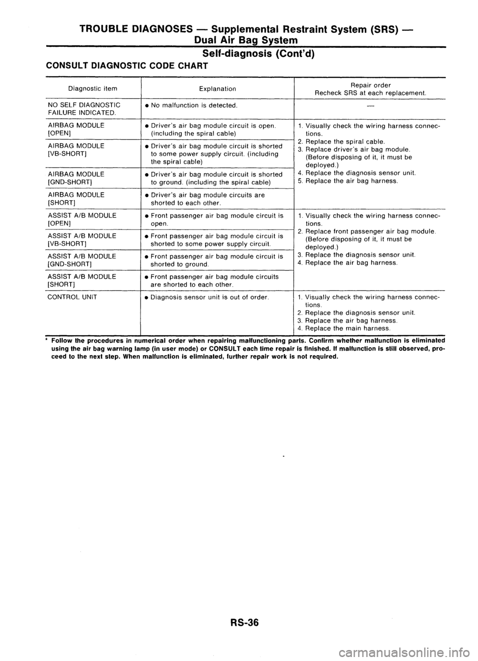
CONSULT DIAGNOSTIC CODECHART
Diagnostic item
Explanation Repair
order
Recheck SRSateach replacement.
NO SELF DIAGNOSTIC
•No malfunction isdetected.
-
FAILURE INDICATED.
AIRBAG MODULE
•Driver's airbag module circuitisopen.
1.
Visually checkthewiring harness connec-
[OPEN) (includingthespiral cable)
tions.
AIRBAG MODULE
•Driver's airbag module circuitisshorted 2.
Replace thespiral cable.
3. Replace driver'sairbag module.
[VB-SHORT] tosome power supply circuit. (including
(Beforedisposing ofit,itmust be
the spiral cable)
deployed.)
AIRBAG MODULE
•Driver's airbag module circuitisshorted 4.
Replace thediagnosis sensorunit.
[GND-SHORT] toground. (including thespiral cable) 5.
Replace theairbag harness.
AIRBAG MODULE
•Driver's airbag module circuitsare
[SHORT] shortedtoeach other.
ASSIST A/BMODULE •Front passenger airbag module circuitis
1.
Visually checkthewiring harness connec-
[OPEN] open. tions.
ASSIST A/BMODULE
•Front passenger airbag module circuitis2.
Replace frontpassenger airbag module.
(Before disposing ofit,itmust be
[VB-SHORT] shortedtosome power supply circuit.
deployed.)
ASSIST A/BMODULE •Front passenger airbag module circuitis3.
Replace thediagnosis sensorunit.
[GND-SHORT) shortedtoground. 4.
Replace theairbag harness.
ASSIST A/BMODULE •Front passenger airbag module circuits
[SHORT] areshorted toeach other.
CONTROL UNIT
•Diagnosis sensorunitisout oforder.
1.
Visually
checkthewiring harness connec-
tions.
2. Replace thediagnosis sensorunit.
3. Replace theairbag harness.
4. Replace themain harness.
*
Follow theprocedures innumerical orderwhenrepairing malfunctioning parts.Confirm whether malfunction iseliminated
using theairbag warning lamp(inuser mode) orCONSULT eachtimerepair isfinished.
If
malfunction isstill observed, pro-
ceed tothe next step. When malfunction iseliminated, furtherrepairworkisnot required.
RS-36
Page 1657 of 1701
TROUBLEDIAGNOSES -Supplemental RestraintSystem(SRS)
Dual AirBag System
Self-diagnosis
(Cont'd)
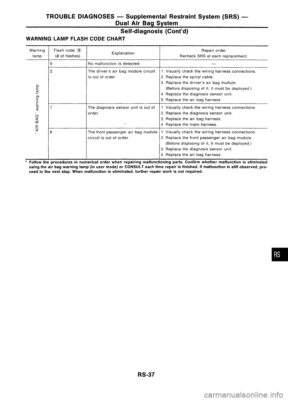
WARNING LAMPFLASH CODECHART
Warning Flashcode
@
Explanation Repair
order
lamp (#offlashes)
RecheckSRSateach replacement.
0
Nomalfunction isdetected.
-
2 The
driver's airbag module circuit
1.Visually checkthewiring harness connections.
is out oforder.
2.Replace thespiral cable.
D.
3.
Replace thedriver's airbag module.
E
(Before
disposing ofit,itmust bedeployed.)
(Ij
-
4.Replace thediagnosis sensorunit.
en
c
5.Replace theairbag harness.
c
ca
7
The
diagnosis sensorunitisout of 1.Visually checkthewiring harness connections.
~
order. 2.
Replace thediagnosis sensorunit.
C)
3.Replace theairbag harness.
«
OJ
.
4.Replace themain harness .
cr:
;:(
8
The
front passenger airbag module 1.Visually checkthewiring harness connections.
circuit isout oforder. 2.Replace thefront passenger airbag module.
(Before disposing of
it,it
must bedeployed.)
3. Replace thediagnosis sensorunit.
4. Replace theairbag harness.
* Follow theprocedures innumerical orderwhen repairing malfunctioning parts.Confirm whether malfunction iseliminaled
using theairbag warning lamp(inuser mode) orCONSULT eachtimerepair isfinished. Ifmalfunction isstill observed, pro-
ceed tothe next step. When malfunction iseliminated, furtherrepairworkisnol required.
RS-37
•
Page 1665 of 1701
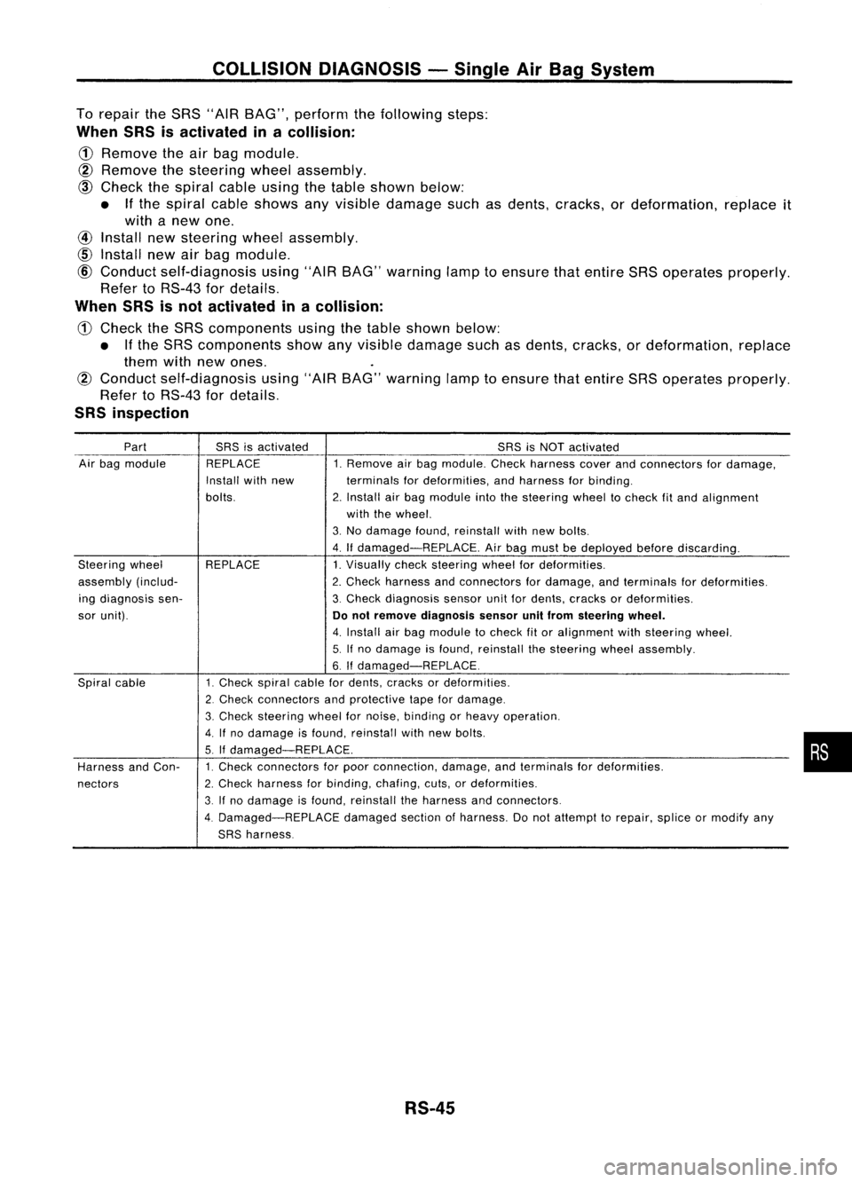
COLLISIONDIAGNOSIS -Single AirBag System
To repair theSRS "AIR BAG", perform thefollowing steps:
When SRSisactivated inacollision:
CD
Remove theairbag module.
@
Remove thesteering wheelassembly.
@)
Check thespiral cableusingthetable shown below:
• Ifthe spiral cableshows anyvisible damage suchasdents, cracks, ordeformation, replaceit
with anew one.
@
Install newsteering wheelassembly.
CID
Install newairbag module.
@
Conduct self-diagnosis using"AIRBAG" warning lamptoensure thatentire SRSoperates properly.
Refer toRS-43 fordetails.
When SRSisnot activated inacollision:
CD
Check theSRS components usingthetable shown below:
• Ifthe SRS components showanyvisible damage suchasdents, cracks, ordeformation, replace
them withnewones.
@
Conduct self-diagnosis using"AIRBAG" warning lamptoensure thatentire SRSoperates properly.
Refer toRS-43 fordetails.
SRS inspection
Part SRSisactivated SRSisNOT activated
Air bag module REPLACE 1.Remove airbag module. Checkharness coverandconnectors fordamage,
Install withnew terminalsfordeformities, andharness forbinding.
bolts. 2.Install airbag module intothesteering wheeltocheck fitand alignment
with thewheel.
3. No damage found,reinstall withnewbolts.
4. Ifdamaged-REPLACE. Airbag must bedeployed beforediscarding.
Steering wheel REPLACE 1.Visually checksteering wheelfordeformities.
assembly (includ- 2.Check harness andconnectors fordamage, andterminals fordeformities.
ing diagnosis sen- 3.Check diagnosis sensorunitfordents, cracks ordeformities.
sor unit).
Donot remove diagnosis sensorunitfrom steering wheel.
4. Install airbag module tocheck fitor alignment withsteering wheel.
5. Ifno damage isfound, reinstall thesteering wheelassembly.
6.
If
damaged-REPLACE.
Spiral cable 1.Check spiralcablefordents, cracks ordeformities.
2. Check connectors andprotective tapefordamage.
3. Check
steering wheelfornoise, binding orheavy operation.
4.
If
no damage isfound, reinstall withnewbolts.
5. If
damaged-REPLACE.
Harness andCon- 1.
Check connectors forpoor connection, damage,andterminals fordeformities.
nectors 2.
Check harness forbinding, chafing,cuts,ordeformities.
3. Ifno damage isfound, reinstall theharness andconnectors.
4. Damaged-REPLACE damagedsectionofharness. Donot attempt torepair, spliceormodify any
SRS harness.
RS-45
•
Page 1672 of 1701
ON-VEHICLESERVICE
Checking andAdjusting DriveBelts(Forpower
steering)
Refer to"Checking DriveBelts" for"ENGINE MAINTENANCE"
in MA section.
SST476C
S
r
SST681B Checking
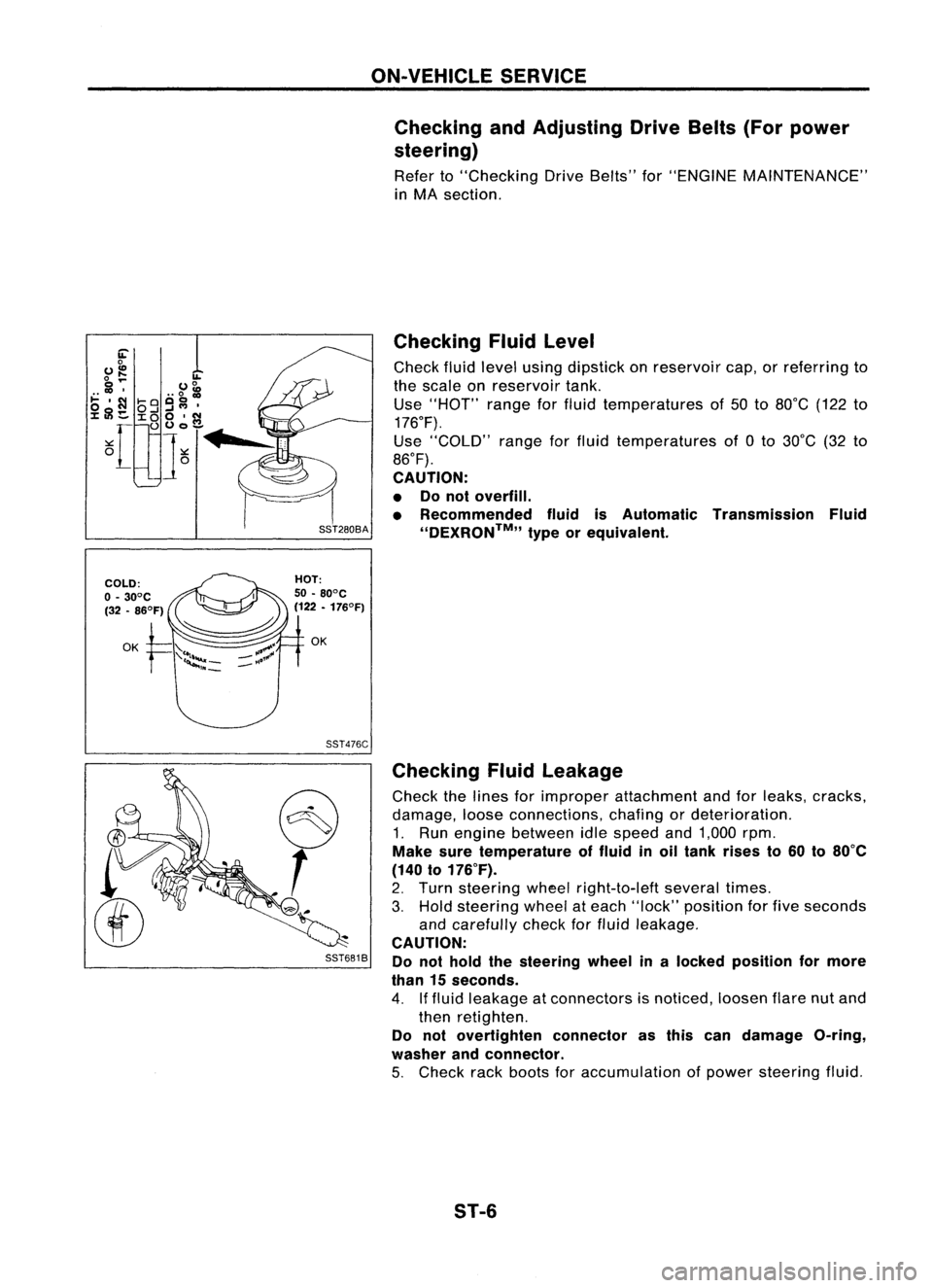
Fluidlevel
Check fluidlevel using dipstick onreservoir cap,orreferring to
the scale onreservoir tank.
Use "HOT" rangeforfluid temperatures of50 to80°C (122to
176°F).
Use "COLD" rangeforfluid temperatures of0to 30°C (32to
86°F).
CAUTION:
• Donot overfill.
• Recommended fluidisAutomatic Transmission Fluid
''DEXRON™,, typeorequivalent.
Checking Fluidleakage
Check thelines forimproper attachment andforleaks, cracks,
damage, looseconnections, chafingordeterioration.
1. Run engine between idlespeed and1,000 rpm.
Make suretemperature offluid inoil tank rises to60 to80°C
(140 to176°F).
2. Turn steering wheelright-to-Ieft severaltimes.
3. Hold steering wheelateach "lock" position forfive seconds
and carefully checkforfluid leakage.
CAUTION:
Do not hold thesteering wheelinalocked position formore
than 15seconds.
4. Iffluid leakage atconnectors isnoticed, loosenflarenutand
then retighten.
Do not overtighten connectorasthis candamage O-ring,
washer andconnector.
5. Check rackboots foraccumulation ofpower steering fluid.
ST-6