Page 1422 of 1701

TROUBLEDIAGNOSES
Preliminary Check
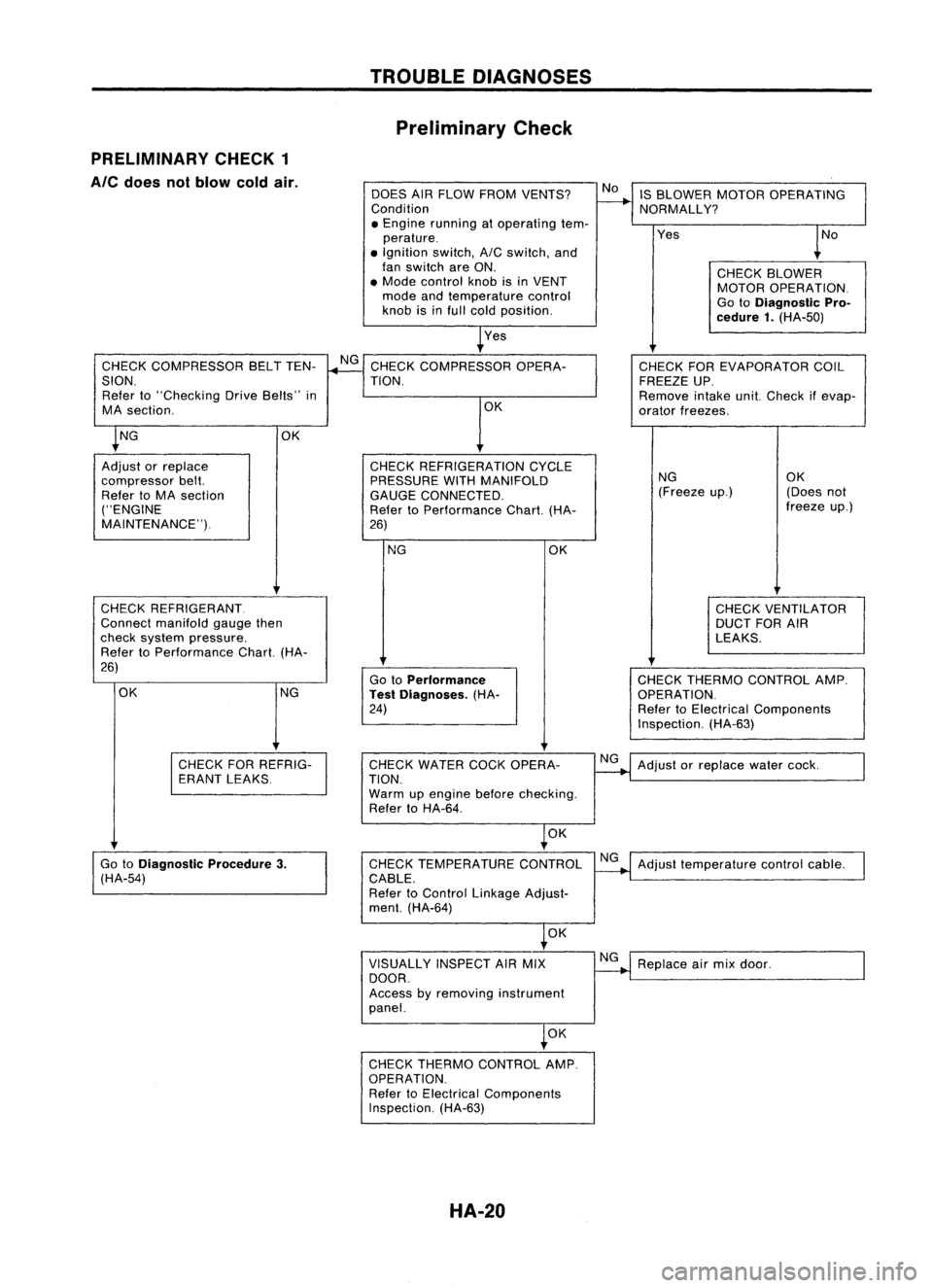
PRELIMINARY CHECK1
Ale
does notblow coldair.
DOESAIRFLOW FROM VENTS?
Condition
• Engine running atoperating tem-
perature .
• Ignition switch,AICswitch, and
fan switch areON.
• Mode control knobisin VENT
mode andtemperature control
knob isinfull cold position.
Yes IS
BLOWER MOTOROPERATING
NORMALLY?
Yes
CHECKBLOWER
MOTOR OPERATION.
Go toDiagnostic Pro-
cedure 1.(HA-50)
CHECK COMPRESSOR BELTTEN-
SION. Refer to"Checking DriveBelts" in
MA section.
CHECK REFRIGERANT.
Connect manifold gaugethen
check system pressure.
Refer toPerformance Chart.(HA-
26)
NG CHECK
THERMO CONTROL AMP.
OPERATION.
Refer toElectrical Components
Inspection. (HA-63)
CHECK
FOREVAPORATOR COIL
FREEZE UP.
Remove intakeunit.Check ifevap-
orator freezes.
NG OK
(Freeze up.) (Doesnot
freeze up.)
CHECK VENTILATOR
DUCT FORAIR
LEAKS.
OK
Go toPerformance
Test Diagnoses. (HA-
24)
NG
CHECK
REFRIGERATION CYCLE
PRESSURE WITHMANIFOLD
GAUGE CONNECTED.
Refer toPerformance Chart.(HA-
26) OK
CHECK
COMPRESSOR OPERA-
TION.
OK
OK NG
Adjust orreplace
compressor belt.
Refer toMA section
("ENGINE
MAINTENANCE").
CHECKFORREFRIG-
ERANT LEAKS CHECK
WATER COCKOPERA-
TION.
Warm upengine beforechecking.
Refer toHA-64.
NG
Adjust orreplace watercock.
OK
Go toDiagnostic Procedure3.
(HA-54) CHECK
TEMPERATURE CONTROL
CABLE.
Refer toControl Linkage Adjust-
ment. (HA-64) NG
Adjust temperature controlcable.
OK
VISUALLY INSPECTAIRMIX
DOOR.
Access byremoving instrument
panel. NG
Replace airmix door.
OK
CHECK THERMO CONTROL AMP.
OPERATION. Refer toElectrical Components
Inspection. (HA-63)
HA-20
Page 1425 of 1701

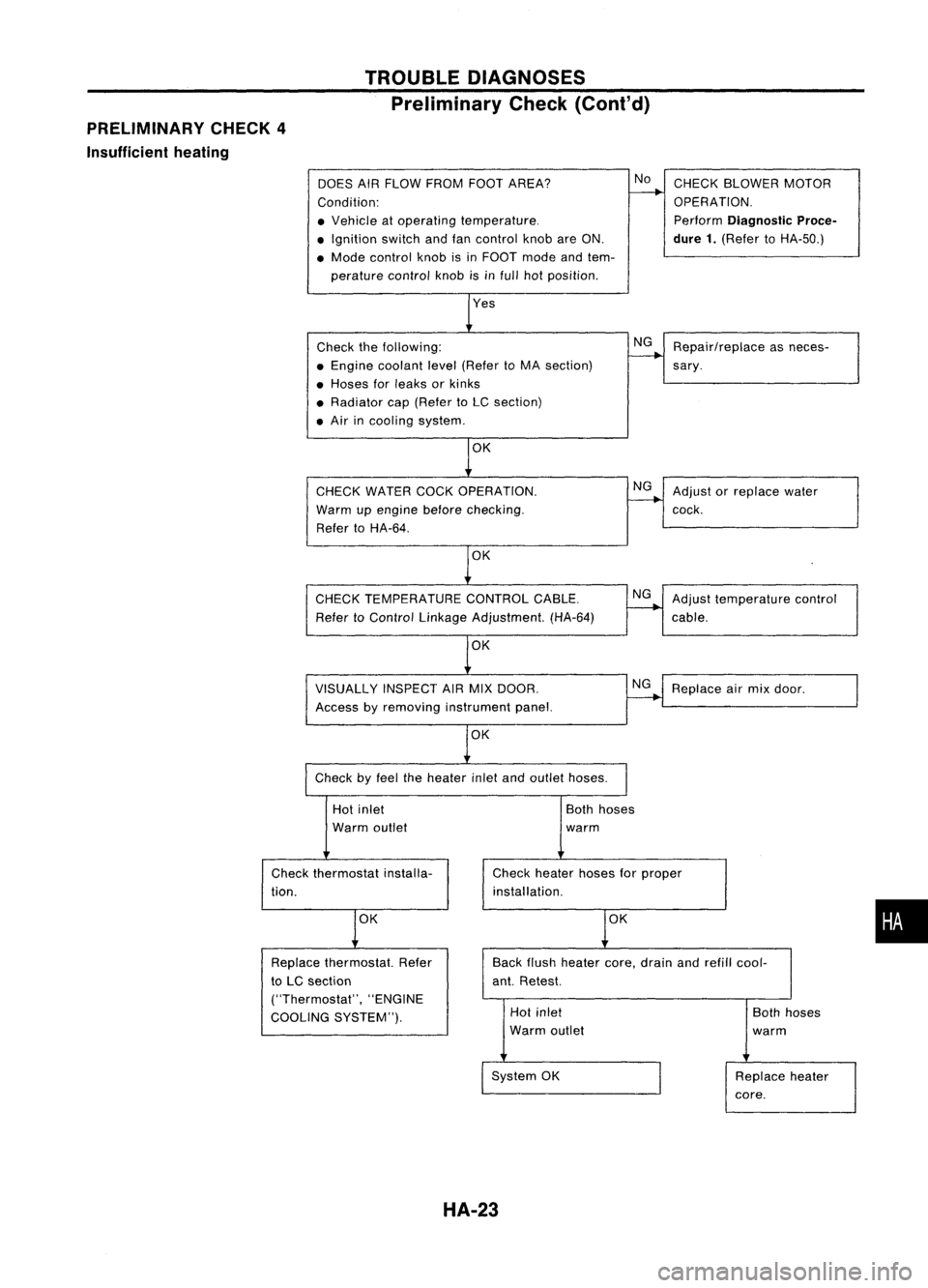
PRELIMINARY CHECK4
Insufficient heating TROUBLE
DIAGNOSES
Preliminary Check(Cont'd)
DOES AIRFLOW FROM FOOTAREA?
Condition:
• Vehicle atoperating temperature .
• Ignition switchandfancontrol knobareON.
• Mode control knobisin FOOT modeandtem-
perature controlknobisinfull hotposition.
Check thefollowing:
• Engine coolant level(Refer toMA section)
• Hoses forleaks orkinks
• Radiator cap(Refer toLC section)
• Air incooling system.
CHECK WATER COCKOPERATION.
Warm upengine before
checking.
Refer toHA-64.
OK
CHECK TEMPERATURE CONTROLCABLE.
Refer toControl Linkage Adjustment. (HA-64)
VISUALLY INSPECTAIRMIX DOOR.
Access byremoving instrument panel.
OK
Check byfeel theheater inletandoutlet hoses.
No
NG
NG
NG
NG
CHECK
BLOWER MOTOR
OPERATION.
Perform
Diagnostic Proce-
dure 1.
(Refer toHA-50.)
Repair/replace asneces-
sary .
Adjust orreplace water
cock.
Adjust temperature control
cable.
Replace airmix door.
Hot inlet
Warm outlet
Check thermostat installa-
tion.
OK
Both
hoses
warm
Check heater hosesforproper
installation.
OK
•
Back
flush heater core,drain andrefill cool-
ant. Retest.
Replace
thermostat. Refer
to LC section
("Thermostat", "ENGINE
COOLING SYSTEM"). Hot
inlet
Warm outlet
System OK
HA-23
Both
hoses
warm
Replace heater
core.
Page 1435 of 1701
Thermocontrolamp.
(M61)
\--7/
LHD
models TROUBLE
DIAGNOSES
Harness Layout
(Cont'd)
I
HA-33
,-
.....
I \
I
l~'
\
RHA324F
•
Page 1436 of 1701
TROUBLEDIAGNOSES
Circuit Diagram -Air Conditioner
DUAL-PRESSURE
SWITCH
AIR
CONDITIONER
RELAY
THERMO
CONTROL
AMP.
IT
o
f-
U1
H
~
IT
W
I
f-
AIC
SWITCH
M
BLOWER
MOTOR
FAN
RESISTOR
GE
C
FAN SWITCH
OFF1234
GA
D
o
uo
HH
[LO
IZW
>w>
U..J....J
404
HUJ>
IT
o
..JI-
«u
~w
IT
I-
wo
IIT
f-(L
IT
o
U1
U1
W
IT
(L
~
o
u
RECIRCULA
nON
SWITCH
1
AIT models
MIT
models
For Europe andIsrael
Except
@
GA engine models
Except
f
or Europe, Israe 1and Austra 1ia
GA eng ine
f
or Europe, Israe1and Austra 1ia and SReng Ine
Except
@
LHD
AIT
models forEurope without daytIme lightsystem
Except
@
41.
@
44
@:
@:
@:
@:
@:
@:
@:
@:
:
@:
*1
To
illumination
system
HHA001
HA-34
Page 1443 of 1701
TROUBLEDIAGNOSES
Wiring Diagram -
A/C -
(Cont'd)
•
OUAl-
PRESSURE
SWITCH
m:@
Refer tolast page
(Foldout page).
(~)
~
,
t
(b):
lHOmode Is
RHOmodels
@:
GAengine forEurope, Israel
o
andAustralia andSRengine
~ @:
Except@
+
R
@:
Except forEurope, Israel
'j/
andAustralia
.l,m..l:.~
*4...
(b)
G/8,
GY
I~I
II
3.e
II
*5',,@y
,@l
""'iF'
CMID CHID
G G *6...
@
S8
@
RIL
,
~OL>
@*7"'@Y,@G
"1"--1
XE*8".@G ,@R/l
~O ......-.-_.
G*8
y~}
Nextpage
-------:~
~
OUAl-
PRESSURE
SWITCH
~:@
THERMISTOR
I6j:JJ
*6
•
o
_loJt
~
S8 S8
I$ICBID 1r$J1CMID
S8
m
S8
m
* __
1>
•
S8
m
~
lOW HIGH
... ...,..
-.
NORMAL
-
Preceding
-
-
*4
0
page
~~
cftID~
2 W 12 8
3
HA-A/C-04
Preceding ~*5
---------O~ ..
-----I
page ~
+
To HA-AlC-02
lG/R ~
IFti
~--:t>
LOW•HIGH
THERMO YY ......,..-.
CONTROL
r.!"~ ~~
NORMAL
A~~FIER "¥JICHID"~AIICHID
lUll
y y
=r'
<;>
@
I
0--1,-0
~
G G
I$I~II~I~
CMID
'"T'
CBID
G G
GX .~
@
o~o--l
• ....*7
-B>
Nextpage
HHA005
HA-41
Page 1451 of 1701
TROUBLEDIAGNOSES
Main Power Supply andGround CircuitCheck
POWER SUPPLY CIRCUIT CHECKFORAICSYSTEM
Check powersupply circuitforairconditioning system.
Refer to"POWER SUPPLYROUTING" inEL section andWiring
Diagram.
Voltmeterterminal
THERMO
CONTROL AMP.CHECK
Check powersupply circuitforthermo controlamp.withignition
switch ON.
1~ Disconnect thermocontrolamp.harness connector.
2. Connect voltmeter fromharness side.
3. Measure voltageacrossterminal No.
CD
and body ground.
Ohmmeter terminal
Turn
AIC
andfanswitches ON.Check bodyground circuitfor
thermo controlamp.
1. Disconnect thermocontrolamp.harness connector.
2. Connect ohmmeter fromharness side.
3. Check forcontinuity betweenterminalNo.@and body
ground.
~I()~
Thermo controlamp.
connector@
Lom ~
RHA341F
~Iv~
Thermo controlamp.
connector
@
;
~~.
LHD 2 \... ~
models:
GIS
Uw-i
RHD [][]
models: GY
Continuity exists:OK
'="RHA342F
EB
CD
EB
@
HA-49
e
Body ground
e
Body ground Voltage
Approx. 12V
Continuity
Yes
•
Page 1457 of 1701

•
Replace
dual-pressure
switch.
Note:
If
the result isNG after
checking circuitcontinuity,
repair harness orconnector.
NG
Note
Note
OK
OK
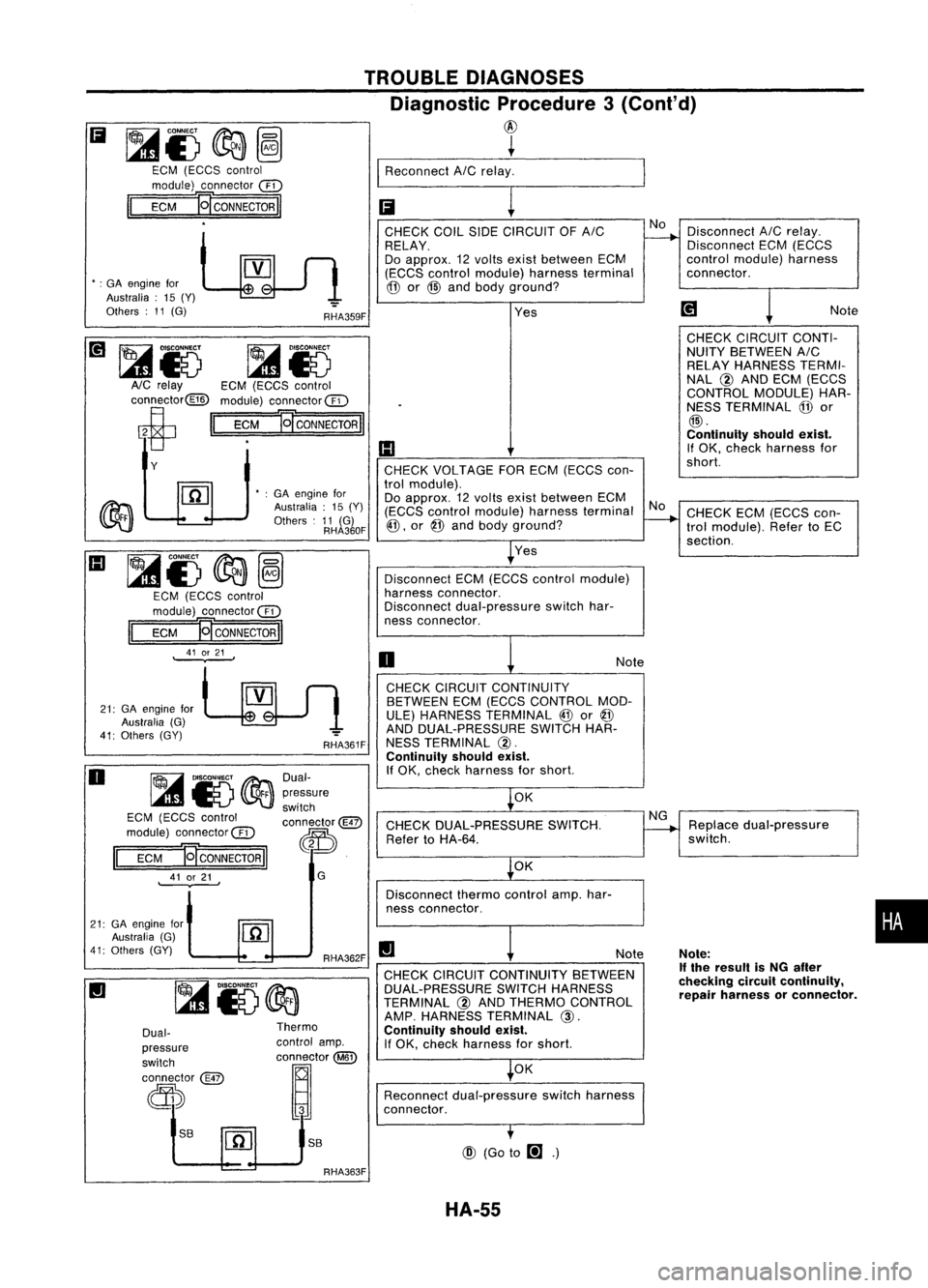
CHECK DUAL-PRESSURE SWITCH.
Refer toHA-64.
Disconnect thermocontrolamp.har-
ness connector.
CHECK
CIRCUIT CONTINUITY
BETWEEN ECM(ECCS CONTROL MOD.
ULE) HARNESS TERMINAL
@
or
@
AND DUAL-PRESSURE SWITCHHAR-
NESS TERMINAL @.
Continuity shouldexist.
If OK, check harness forshort.
OK
@ (Go to
m .)
Disconnect
ECM(ECCS contraImodule)
harness connector.
Disconnect dual-pressure switchhar-
ness connector.
CHECK CIRCUIT CONTINUITY BETWEEN
DUAL.PRESSURE SWITCHHARNESS
TERMINAL @AND THERMO CONTROL
AMP. HARNESS TERMINAL
@.
Continuity shouldexist.
If OK, check harness forshort.
Reconnect dual-pressure switchharness
connector.
o
CHECK
COILSIDECIRCUIT OFAIC No
Disconnect A/Crelay.
~
RELAY. Disconnect
ECM(ECCS
Do approx. 12volts exist between ECM control
module) harness
(ECCS control module) harnessterminal connector.
@
or@ and body ground?
l
Yes
~Note
CHECK CIRCUIT CONTI-
NUITY BETWEEN AIC
RELAY HARNESS TERMI-
NAL @AND ECM (ECCS
CONTROL MODULE)HAR-
.
NESSTERMINAL
@
or
@.
Continuity shouldexist.
(I) If
OK, check harness for
CHECK VOLTAGE FORECM (ECCS con- short.
tral module) .
Do approx. 12volts exist between ECM
NoCHECK ECM(ECCS con-
(ECCS
control module) harnessterminal
-..
@, or@ and body ground?
trolmodule). RefertoEC
section.
Yes
TROUBLE
DIAGNOSES
Diagnostic Procedure3(Conl'd)
@
~
I
Reconnect AICrelay. _
Ii
!
RHA359F
RHA362F
II
RHA361F
G
Dual-
pressure
switch
connector@
~.
S8
Thermo
control amp.
OOD
tm
@
•
:GA engine for
Australia :15 (Y)
Others :11 (G)
RHA360F
S8
Dual-
pressure
switch
connector
@
d))
~15@a
EGM (EGGS control
module) connec1or@
EGM
E[CONNECTORII
41 or21
.
II
•
:GA engine for
Australia: 15(Y)
Others :11 (G)
21: GAengine for
Australia (G)
41: Others (GY)
~&)
~Io
AlG relay EGM(EGGS control
connector@ module)connector@
ci
II
EGM
]g
CONNECTOR
II
Y
21: GAengine for
Australia (G)
41: Others (GY)
Ii
~i)@a~
EGM (EGGS control
module) connector @
II
EGM
]g
CONNECTOR
II
o
III
~i)
@a~
EGM (EGGS control
module) connector@
II
EGM 'gCONNECTORII
41 or21
.
RHA363F HA-55
Page 1458 of 1701

~CONNECT ~
(gl
l41E) ~
@
EGM (EGGS control
module) connector
@
II
EGM
J9"CONNECTORII
11 TROUBLE
DIAGNOSES
Diagnostic Procedure3
(Co nt'd)
~ ~
I
Reconnect AICrelay_. _..._
II
!
EGM (EGGS control Dual-pressure
module) connector
@
switch connector
@
II
ECM
Ej'coNNEcTORII ~
11
GSHA734E
Note
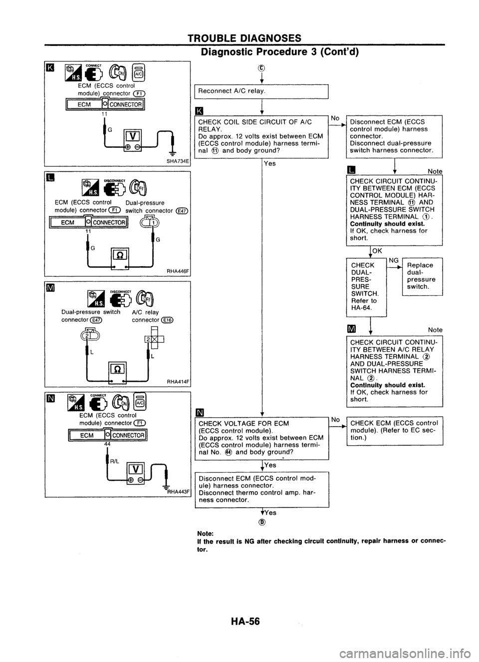
CHECK CIRCUIT CONTINU-
ITY BETWEEN ECM(ECCS
CONTROL MODULE)HAR-
NESS TERMINAL @AND
DUAL-PRESSURE SWITCH
HARNESS TERMINAL
CD.
Continuity shouldexist.
If OK, check harness for
short. Disconnect
ECM(ECCS
control module) harness
connector. Disconnect dual-pressure
switch harness connector.
II
CHECK
COILSIDECIRCUIT OFAIC
RELAY.
Do approx. 12volts exist between ECM
(ECCS control module) harnesstermi.
nal @and body ground?
Yes
G
II
G
Dual-pressure switch
connector@ RHA446F
NC relay
connector@ ~OK
CHECK
DUAL-
PRES-
SURE
SWITCH. Refer to
HA-64. NG
--+
Replace
dual-
pressure
switch.
Note
"='RHA443F
~i)~@
EGM (EGGS control
module) connector@
II
EGM
E[CONNECTORII
44
L
R/L
L
RHA414F
II
CHECK VOLTAGE FORECM
(ECCS control module).
Do approx. 12volts exist between ECM
(ECCS control module) harnesstermi-
nal No.
@
and body ground?
Yes
Disconnect ECM(ECCS control mod-
ule) harness connector.
Disconnect thermocontrol amp.har-
ness connector.
No
CHECK
CIRCUIT CONTINU-
ITY BETWEEN AICRELAY
HARNESS TERMINAL
@
AND DUAL-PRESSURE
SWITCH HARNESS TERMI-
NAL @.
Continuity shouldexist.
If OK, check harness for
short.
CHECK ECM(ECCS control
module). (RefertoEC sec-
tion.)
Yes
@
Note:
If the result isNG after checking circuilcontinuity, repairharness orconnec-
tor.
HA-56