Page 1133 of 1701
TROUBLEDIAGNOSES
Air Conditioner CutControl (Cont'd)
LHD models
EC-A/CCUT-01
Refer toEL-POWEA.
OFF
LG/R~
I
,
I
I
ON
A/C
LG/R
I
SWITCH
m
I
OFF
@
I
THERMO
CONTROL
AMP.
~
ON
L/Y
~ ~
G/B G/BG/Y
THERMISTOR
I I
m
._-~--_. rn
JUNCTION
BOX
NO.2
To compressor (JOINT
._ L/R. (Referto CONNECTORS)
I
HA-A/C.)~~
G/Y
00
~E~N~~gD
I?iJ
~~~TCH
VALVE OFF--~
IkjJ
(E64) ~
B (E65) B
I
r1
I
• .., BBB
1 ~
1
i....l
mm ~~
RIL
~
t
FUSE
BLOCK
(JIB)
~
(BOO)
R/L
IriDl
A/C
DUAL-
PRESSURE SWITCH
~
1~11I~211~1
LIB LG/R LG/R
II-~ --
LIB
L/Y
IT ~IA/C
n
RELAY
U
UID
4=JJ~
L L/R
~L
rn
I
ECM(ENGINECONTROLMODULE)
---------- @
n
LOW HIGH
... ~~_.
NORMAL
I!4Jl
G
~~1;1$1
G
m
COMP
~(E16)
T
L
JS4.ffi
(tiS)
B
~-----------.,
I I
:ITl~ ~~:
I I
L
~
IQl@
~ W
Refer
tolast page
(Foldout page).
CMID
(El0n
,
lf1@
(E106)
,
~
HEC095
EC-414
Page 1134 of 1701
TROUBLEDIAGNOSES
Air Conditioner CutControl (Cont'd)
RHO models
EC-A/CCUT-02
•
A/C
SWITCH
@
~
LG/B
ON
OFF
I
I
I
ON
I
I
OFF
I
LG/R~
Refer
toEL-POWER.
THERMISTOR
---I
THERMO
LG RCONTROL
m AMP.~
~
~GY~
R/L
~
IACV-FICD
SOLENOID
VALVE
(E101)
(BID
@!QD~
- L/R ~ L/R~ L/R-e=~Y,
B
'-B~
To compressor • LG/B
- L/R.
(~~~~/C
tf ~
I
. ffi
~~:CTOR-4 OFF--ON~~;CH
t
W ~
B B
+--,
n
I
B BB BB
1
t..lt..l
@
FUSE
BLOCK
(JIB)
@g)
R/L
Irfnl
A/C
I
ECM
(ENGINE
CONTROL
MODULE)
~---------@
UQ-lil
I
N.21
I
N.21
LIB LG/R LG/R
I
I
I
LIB L/Y
IT ]/,/c
n
RELAY
U~
~lbi=ll
L L/R
r
L..
m
L
OUAL-
LOW HIGH PRESSURE
... _e SWITCH
NORMAL
ffi
4=U
G
db (E101)
I~I(][)
G
m
COMP
r----------.,
J
I
1Ql ~
I
F.1
(B10n
B
(B102)
I
ITI:illIIITIIII
@~ ~
C!J.S)
BI~ B~ BI~ P123456 W
I I
L
.J
A~
T
L
L'Ql@
[[[g@]
W
Refer
tolast page
(Foldout page).
(BID
(E101)
,
~
,
HEC096
EC-415
Page 1139 of 1701

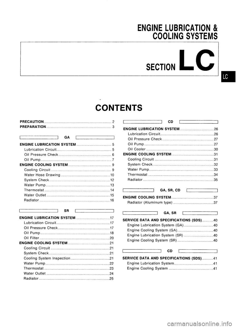
ENGINELUBRICATION
&
COOLING SYSTEMS
SECTION
LC
CONTENTS
•
PRECAUTION
2
PREPARATION
3
GA
ENGINE LUBRICATION SYSTEM
5
Lubrication Circuit.. 5
Oil Pressure Check 6
Oil Pump 7
ENGINE COOLING SySTEM 9
Cooling Circuit 9
Water HoseDrawing 10
System Check 12
Water Pump 13
Thermostat 14
Water Outlet 15
Radiator 16
SR
ENGINE LUBRICATION SYSTEM 17
Lubrication Circuit. 17
Oil Pressure Check 17
Oil Pump 18
Oil FiIter 20
ENGINE COOLING SYSTEM 21
Cooling Circuit 21
System Check 21
Cooling SystemInspection 21
Water Pump 22
Thermostat 23
Water Outlet 24
Radiator 25CO
ENGINE LUBRICATION SYSTEM 26
Lubrication Circuit... 26
Oil Pressure Check 27
Oil Pump ,27
Oil Cooler 30
ENGINE COOLING SYSTEM 31
Cooling Circuit 31
System Check 32
Water Pump ,33
Thermostat 34
Radiator 35
GA,SR,CO
ENGINE COOLING SYSTEM 37
Radiator (Aluminum type) 37
GA,SR
SERVICE DATAANDSPECIFICATIONS (SOS)40
Engine Lubrication System(GA) 40
Engine Cooling System(GA) 40
Engine Lubrication System(SR) 40
Engine Cooling System(SR) 40
CO
SERVICE DATAANDSPECIFICATIONS (SOS)41
Engine Lubrication System .41
Engine Cooling System 41
Page 1147 of 1701
ENGINECOOLING SYSTEM
Cooling Circuit
Reservoir tank
...Thermostat: OPEN
~ Thermostat: CLOSED
•
Water outlet Thermostat
housing
Throttlebody
Intake manifold Heater
SLC9S7AA
LC-9
Page 1148 of 1701
ENGINECOOLING SYSTEM
Water HoseDrawing
GA14DE andGA16DE withoutVTC
GA 16DE withVTCexcept forAustralia GA15DE
MLC084A
CD
Intake manifold tothermostat
housing-1
@
Intake manifold tothermostat
housing-2
@
Radiator lowerhosetowater
inlet
@
Intake manifold tothrottle body
LC-10
@
Throttle bodytothermostat
housing
Page 1149 of 1701
ENGINECOOLING SYSTEM
Water HoseDrawing (Cont'd)
GA16DE withVTCforAustralia
Intakemanifold
5
9
•
Q)
Intake manifold toThermostat
housing (upper)
@
Intake manifold toThermostat
housing (lower)
@
Water jacket toWater pipe
lower
@
Water pipelower
CID
Water pipelower toThrottle
body
@
Water pipelower toIntake
manifold
(J)
Water pipeupper
LC-11 @
Throttle bodytoWater pipe
upper
@
Intake manifold toWater pipe
upper
@
Water pipeupper toThermostat
housing
SLC021BA
Page 1152 of 1701
ENGINECOOLING SYSTEM
Water Pump(Cont'd)
INST ALLATION
Use ascraper toremove liquidgasket fromwater pump.
Be sure liquid gasket ingrooves isalso removed.
• Remove liquidgasket frommating surface offront cover.
• Remove alltraces ofliquid gasket usingwhitegasoline.
SLC425A
•Apply liquidgasket tomating surface ofpump housing as
shown.
SLC426A
[J
Liquid gasket
Thermostat housing
7
Ther~st~
W"",?~: .
~. ~~628-634
~ P"L' 'd
(0.641-0.851,
~ IqUI gasket 55.6_73.8)
~6.28 -8.34 (0.641 -0.851, 55.6-73.8)
~: N.m(kg-m. in-Ib) SLC990ACThermostat
INSPECTION
1. Check forvalve seating condition atordinary temperatures.
It
should seattightly.
Up
11
Jiggle
valve
(top side)
SLC499A
SLC343
2.
Check valveopening temperature andmaximum valvelift.
Valve opening temperature °C
CF)
76.5(170)
Valve
lift
mml"C(inI"F) Morethan8190(0.311194)
3. Then check ifvalve closes at5°C (9°F) below valveopening
temperature.
• After installation, runengine forafew minutes, andcheck
for leaks.
LC-14
Page 1153 of 1701
SLC428A
SLC429A
•
Water Outlet
INSPECTION
Visually inspectforwater leaks. Ifthere isleakage, applyliq-
uid gasket.
INSTALLATION
When installing wateroutlet, applyliquid gasket asshown.
ENGINE
COOLING SYSTEM
Thermostat (Cont'd)
INSTALLATION
When installing waterinletapply liquidgasket asshown .
SLC430A
2.0.3.0
mm
(0.079 •0.118 In)die.
LC-15