1995 NISSAN ALMERA N15 Throttle
[x] Cancel search: ThrottlePage 917 of 1701
TROUBLEDIAGNOSIS FORNON-DETECTABLE ITEMS
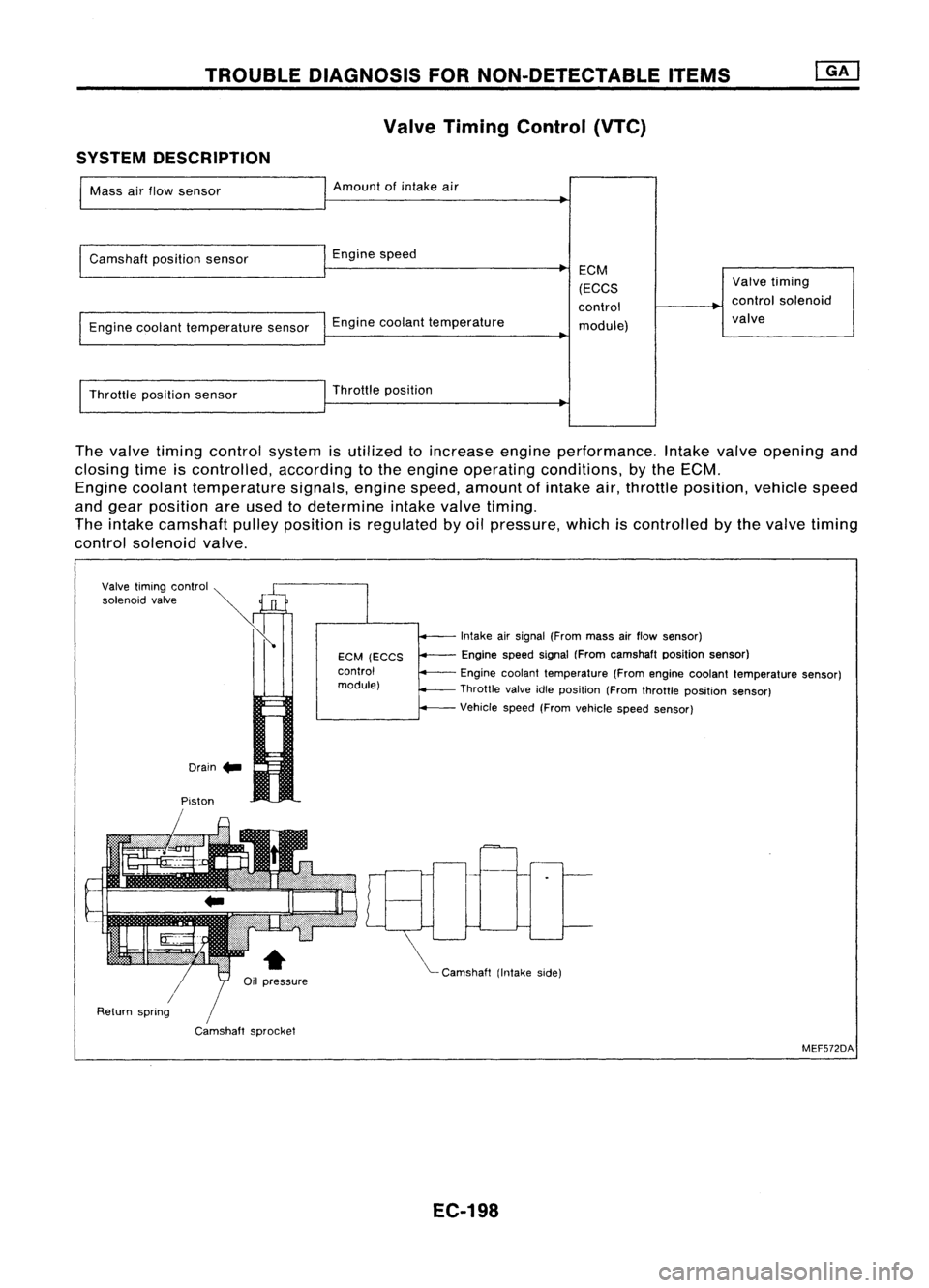
Valve Timing Control (VTC)
SYSTEM DESCRIPTION
Mass airflow sensor Amount
ofintake air
Camshaft positionsensor Enginespeed
Engine coolant temperature sensorEnginecoolant temperature ECM
(ECCS
control module) Valve
timing
control solenoid
valve
Throttle positionsensor Throttle
position
The valve timing control system isutilized toincrease engineperformance. Intakevalveopening and
closing timeiscontrolled, accordingtothe engine operating conditions, bythe ECM.
Engine coolant temperature signals,enginespeed,amount ofintake air,throttle position, vehiclespeed
and gear position areused todetermine intakevalvetiming.
The intake camshaft pulleyposition isregulated byoil pressure, whichiscontrolled bythe valve timing
control solenoid valve.
Drain .. Intake
airsignal (From massairflow sensor)
Engine speedsignal(From camshaft positionsensor)
Engine coolant temperature (Fromengine coolant temperature sensor)
Throttle valveidleposition (Fromthrottle position sensor)
Vehicle speed(Fromvehicle speedsensor)
"'- Camshaft (Intakeside)
EGM
(EGGS
control
module)
/
Camshaft sprocket
Piston
Valve
timing control ~
»
'o'""oid ,,',"
Ii
/
Return spring
MEF572DA
EC-198
Page 940 of 1701
TROUBLEDIAGNOSIS FORNON-DETECTABLE ITEMS~
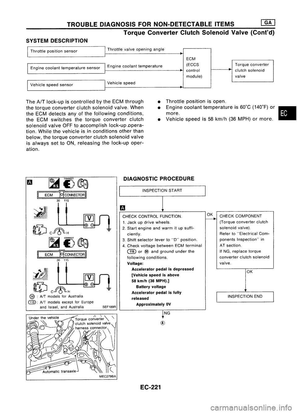
Torque Converter ClutchSolenoid Valve(Cont'd)
SYSTEM DESCRIPTION
Throttle position sensor Throttle
valveopening angle
Engine coolant temperature sensorEnginecoolant temperature ECM
(ECCS
control
module) Torque
converter
clutch solenoid
valve
Vehicle speedsensor Vehicle
speed
The
AfT
lock-up iscontrolled bythe ECM through
the torque converter clutchsolenoid valve.When
the ECM detects anyofthe following conditions,
the ECM switches thetorque converter clutch
solenoid valveOFFtoaccomplish lock-upDpera-
tion. While thevehicle isin conditions otherthan
below, thetorque converter clutchsolenoid valve
is always settoON, releasing thelock-up oper-
ation.
•
•
•
Throttle
position isopen .
Engine coolant temperature is60°C (140°F) or•
more.
Vehicle speedis58 kmfh (36MPH) ormore .
m ~
i3~
II
ECM
HCONNECTORII
30 115
ID
cf6~H
~i3~
II
ECM E
CONNECTOR
II
30 115
iIJ
ID
cf6~H
@> :
AIT
models forAustralia
@:
AlTmodels exceptforEurope
and Israel, andAustralia
SEF189RDIAGNOSTIC
PROCEDURE
INSPECTION START
CHECK CONTROL FUNCTION.
1. Jack updrive wheels.
2. Start engine andwarm itup suffi-
ciently.
3. Shift selector leverto"D" position.
4. Check voltage between ECMterminal
GID
or
@
and ground underthe
following conditions.
Voltage: Accelerator pedalisdepressed
[Vehicle speedisabove
58 km/h (36MPH).]
Battery voltage
Accelerator pedalisfully
released ApprOXimately OV
OK
CHECK COMPONENT
(Torque converter clutch
solenoid valve).
Refer to"Electrical Com-
ponents Inspection" in
AT section.
If NG, replace torque
converter clutchsolenoid
valve.
OK
INSPECTION END
MEC279BA NG
EC-221
Page 950 of 1701
ENGINEANDEMISSION CONTROLOVERALLSYSTEM
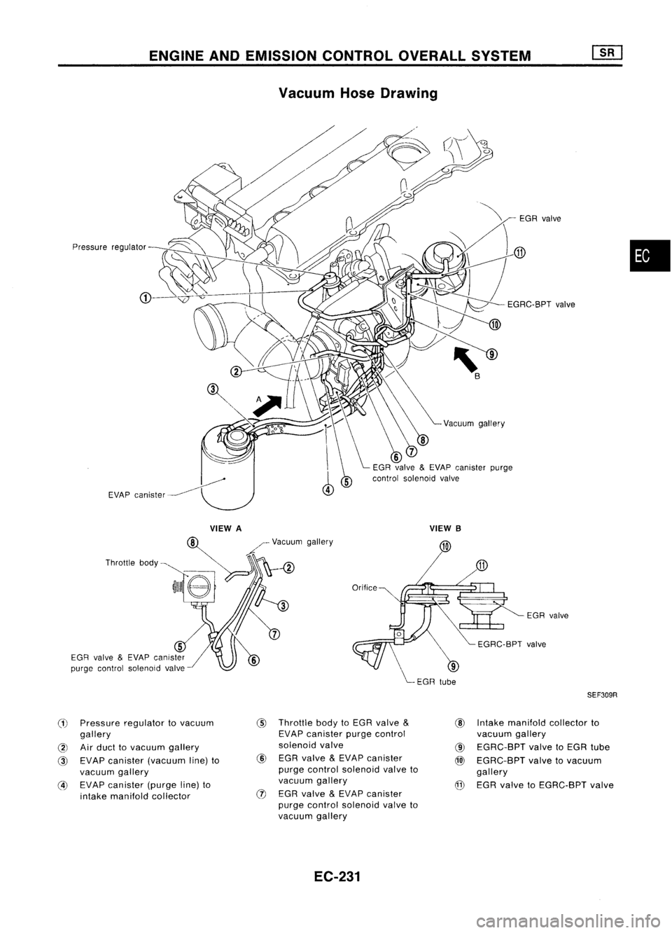
Vacuum HoseDrawing
Pressure regulator
VIEWA
Throttle body~
5
EGR valve
&
EVAP canister
purge control solenoid valve
(1)
Pressure regulator tovacuum
gallery
@
Airduct tovacuum gallery
@
EVAP canister (vacuum line)to
vacuum gallery
@
EVAP canister (purgeline)to
intake manifold collector /-
Vacuum gallery
A
@
Throttle bodytoEGR valve
&
EVAP canister purgecontrol
solenoid valve
@
EGR valve
&
EVAP canister
purge control solenoid valveto
vacuum gallery
(J)
EGR valve
&
EVAP canister
purge control solenoid valveto
vacuum gallery
EC-231 EGR
valve
VIEW B
EGRvalve
SEF309R
@ Intake manifold collectorto
vacuum gallery
@
EGRC-BPT valvetoEGR tube
@
EGRC-BPT valvetovacuum
gallery
@ EGR valve toEGRC-BPT valve
•
Page 951 of 1701
ENGINEANDEMISSION CONTROLOVERALLSYSTEM
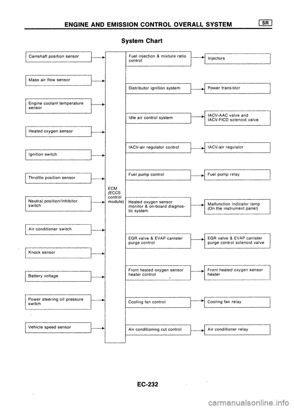
System Chart
Camshaft positionsensor Fuel
injection
&
mixture ratio
•
I
I
control Injectors
Mass airflow sensor
I
Distributorignitionsystem
r
~1
Power transistor
Engine coolant temperature
.
sensor
I
IACV-AAC valveand
Idle aircontrol system
IACV-FICDsolenoidvalve
Heated oxygen sensor
I
IACV-airregulator control
~--..j
IACV-air regulator
I
Ignition switch
I
I
Throttle position sensor
~-+
Fuel
pump control Fuel
pump relay
ECM
(ECCS
control
Neutral position/Inhibitor
.
module) Heatedoxygen sensor
switch monitor
&
on-board diagnos-
~-+
Malfunction
indicatorlamp
tic system (On
theinstrument panel)
I
Air conditioner switch
t~
EGRvalve
&
EVAP canister
1---+
EGR
valve
&
EVAP canister
purge control purge
control solenoid valve
Knock sensor
.....
Frontheated oxygen sensor Front
heated oxygen sensor
Battery voltage
.
heater
control heater
I
.
Power steering oilpressure
~
Coolingfancontrol
--
Cooling
fanrelay
switch
Vehicle speedsensor
.....
Airconditioning cutcontrol Air
conditioner relay
EC-232
Page 952 of 1701
ENGINEANDEMISSION BASICCONTROL SYSTEMDESCRIPTION
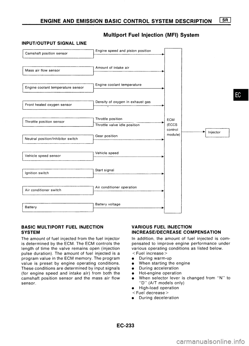
Multiport FuelInjection (MFI)System
INPUT/OUTPUT SIGNALLINE
Camshaft positionsensor
Mass airflow sensor
Engine coolant temperature sensor
Front heated oxygen sensor
Throttle position sensor
Neutral position/lnhibitor switch
I
Vehicle speedsensor
Ignition switch
Air conditioner switch
Battery Engine
speedandpiston position
Amount ofintake air
Engine coolant temperature
Density ofoxygen inexhaust gas
Throttle position
Throttle valveidleposition
Gear position
I
Vehicle speed
Start signal
Air conditioner operation
Battery voltage ECM
(ECCS
control
module) Injector
•
BASIC MULTIPORT FUELINJECTION
SYSTEM
The amount offuel injected fromthefuel injector
is determined bythe ECM. TheECM controls the
length oftime thevalve remains open(injection
pulse duration). Theamount offuel injected isa
program valueinthe ECM memory. Theprogram
value ispreset byengine operating conditions.
These conditions aredetermined byinput signals
(for engine speedandintake air)from boththe
camshaft positionsensorandthemass airflow
sensor.
VARIOUS
FUELINJECTION
INCREASE/DECREASE COMPENSATION
In addition, theamount offuel injected iscom-
pensated toimprove engineperformance under
various operating conditions aslisted below.
<
Fuel increase>
• During warm-up
• When starting theengine
• During acceleration
• Hot-engine operation
• When selector leverischanged from"N"to
"0" (AfT models only)
• High-load operation
<
Fuel decrease>
• During deceleration
EC-233
Page 954 of 1701
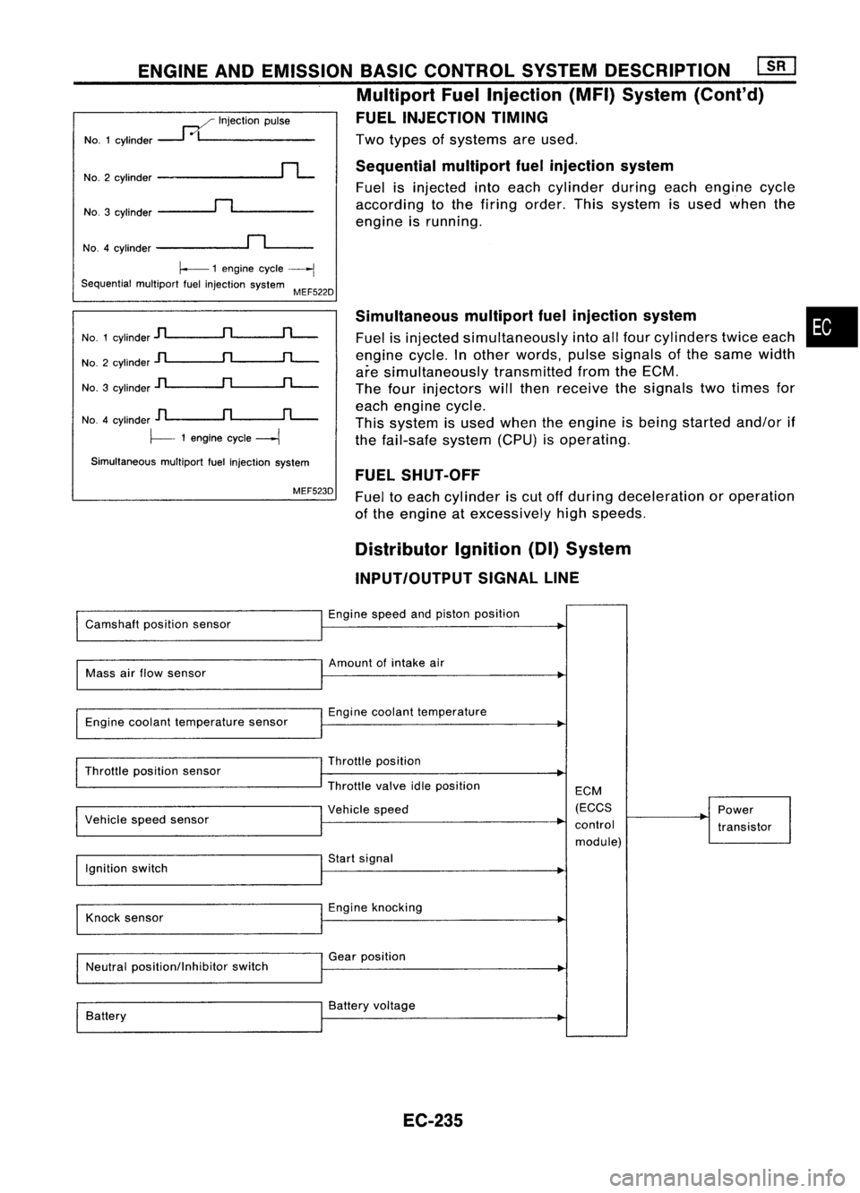
Twotypes ofsystems areused.
Sequential multiportfuelinjection system
Fuel isinjected intoeach cylinder duringeachengine cycle
according tothe firing order. Thissystem isused when the
engine isrunning.
ENGINE
ANDEMISSION BASICCONTROL SYSTEMDESCRIPTION ~
Multiport FuelInjection (MFI)System (Cont'd)
FUEL INJECTION TIMING
..--./ Injection pulse
NO.1 cylinder
---1
0/1 _
NO.3 cylinder
~n~ _
No.2
cylinder
rL
NO.4 cylinder
~n~_
~ 1engine cycle
----j
Sequential multiportfuelinjection system
MEF522D
No. 1cylinder
jl
n
rL-
No. 2cylinder
jl
n
rL-
No. 3cylinder
]l
n
rL-
NO.4 cylinder
D
n
fL-.
~- 1engine cycle
---1
Simultaneous multiportfuelinjection system
MEF523D Simultaneous
multipartfuelinjection system
Fuel isinjected simultaneously intoallfour cylinders twiceeach
engine cycle.Inother words, pulsesignals ofthe same width
are simultaneously transmittedfromtheECM.
The four injectors willthen receive thesignals twotimes for
each engine cycle.
This system isused when theengine isbeing started and/orif
the fail-safe system(CPU)isoperating.
FUEL SHUT-OFF
Fuel toeach cylinder iscut offduring deceleration oroperation
of the engine atexcessively highspeeds.
•
Distributor Ignition(DI)System
INPUT/OUTPUT SIGNALLINE
Camshaft positionsensor Engine
speedandpiston position
Mass airflow sensor Amount
ofintake air
Engine coolant temperature sensor Engine
coolant temperature
Throttle position sensor
I
Vehicle speedsensor Throttle
position
Throttle valveidleposition
I
Vehicle speed ECM
(ECCS
control module) Power
transistor
Ignition switch Start
signal
Knock sensor Engine
knocking
Neutral position/Inhibitor switchGear
position
Battery Battery
voltage
EC-235
Page 955 of 1701
A
N
600 1,000 1,4001,8002,200
Engine speed(rpm) SEF742M
Tp
(msec)
1.75
~ 1.50
.~
3l
1.25
:;
a.
c:
1.00
.Q
~ 0.75
E ENGINE
ANDEMISSION BASICCONTROL SYSTEMDESCRIPTION
Distributor Ignition(01)System (Cont'd)
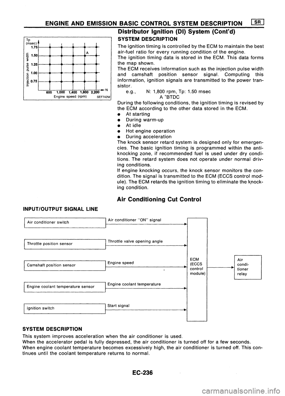
SYSTEM DESCRIPTION
The ignition timingiscontrolled bythe ECM tomaintain thebest
air-fuel ratioforevery running condition ofthe engine.
The ignition timingdataisstored inthe ECM. Thisdataforms
the map shown.
The ECM receives information suchasthe injection pulsewidth
and camshaft positionsensorsignal.Computing this
information, ignitionsignalsaretransmitted tothe power tran-
sistor.
e.g., N:1,800 rpm,Tp:1.50 msec
AOBTDC
During thefollowing conditions, theignition timingisrevised by
the ECM according tothe other datastored inthe ECM.
• Atstarting
• During warm-up
• Atidle
• Hot engine operation
• During acceleration
The knock sensor retardsystem isdesigned onlyforemergen-
cies. Thebasic ignition timingisprogrammed withintheanti-
knocking zone,ifrecommended fuelisused under drycondi-
tions. Theretard system doesnotoperate undernormal driv-
ing conditions.
If engine knocking occurs,theknock sensor monitors thecon-
dition. Thesignal istransmitted tothe ECM (ECCS control mod-
ule). TheECM retards theignition timingtoeliminate thek.nock-
ing condition.
Air Conditioning CutControl
INPUT/OUTPUT SIGNALLINE
Air conditioner switch
Throttle position sensor
Camshaft positionsensor
Engine coolant temperature sensor
Ignition switch Air
conditioner "ON"signal
Throttle valveopening angle
Engine speed
Engine coolant temperature
Start signal
ECM
(ECCS
control module)
Air
condi-
tioner
relay
SYSTEM DESCRIPTION
This system improves acceleration whentheairconditioner isused.
When theaccelerator pedalisfully depressed, theairconditioner isturned offfor afew seconds.
When engine coolant temperature becomesexcessively high,theairconditioner isturned off.This con-
tinues untilthecoolant temperature returnstonormal.
EC-236
Page 957 of 1701
EVAPORATIVEEMISSIONSYSTEM
Description
yAir.. Fuelvapor
EGR
valve
&
EVAP canister purgecontrol
solenoid valve
-
EVAP canister
Vapor
ventline
-
Fuel fillercap
with vacuum
relief valve
t
Fuel tank
MEF609DC
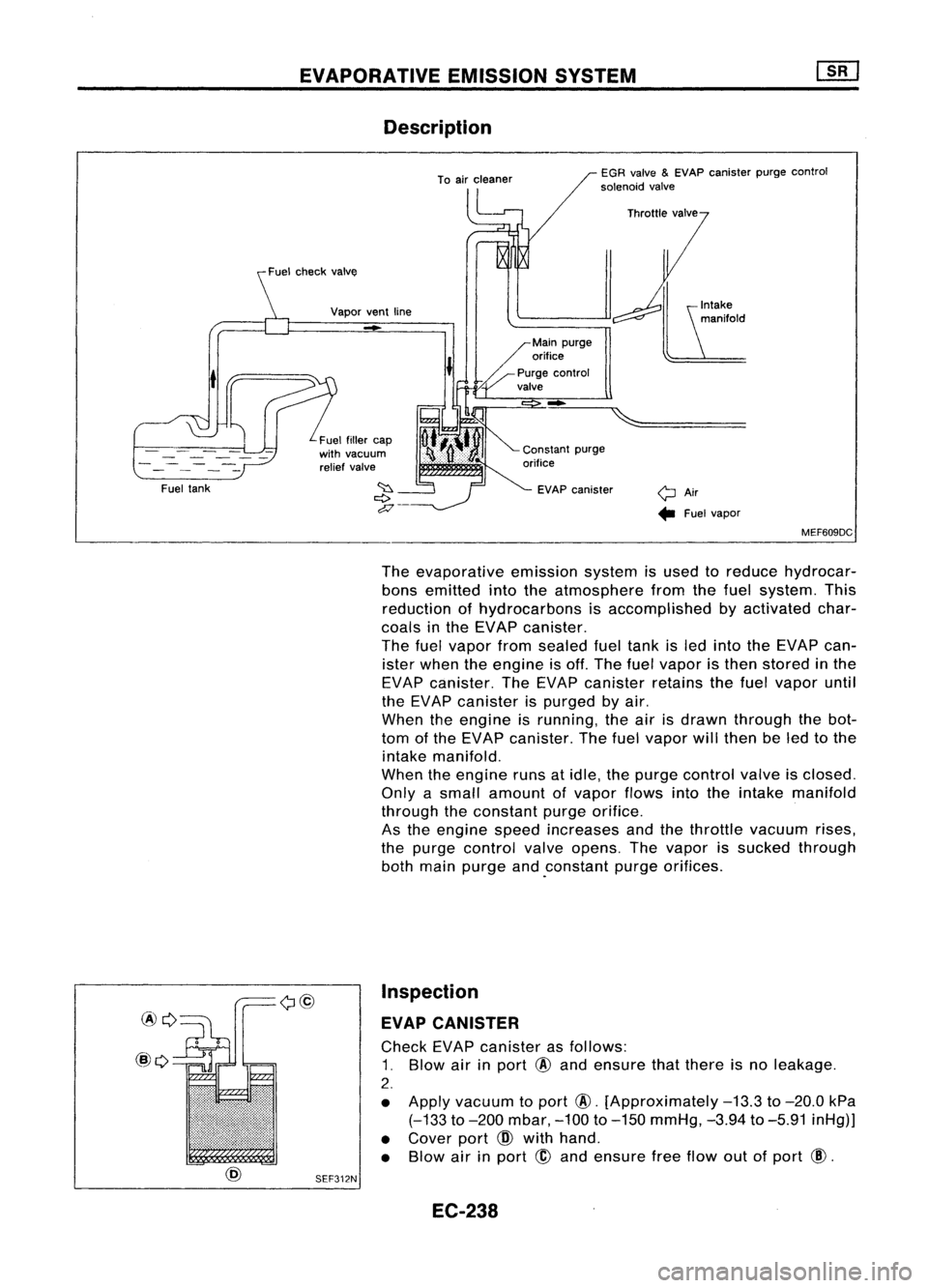
The evaporative emissionsystemisused toreduce hydrocar-
bons emitted intotheatmosphere fromthefuel system. This
reduction ofhydrocarbons isaccomplished byactivated char-
coals inthe EVAP canister.
The fuelvapor fromsealed fueltank isled into theEVAP can-
ister when theengine isoff. The fuelvapor isthen stored inthe
EVAP canister. TheEVAP canister retainsthefuel vapor until
the EVAP canister ispurged byair.
When theengine isrunning, theairisdrawn through thebot-
tom ofthe EVAP canister. Thefuelvapor willthen beled tothe
intake manifold.
When theengine runsatidle, thepurge control valveisclosed.
Only asmall amount ofvapor flowsintotheintake manifold
through theconstant purgeorifice.
As the engine speedincreases andthethrottle vacuum rises,
the purge control valveopens. Thevapor issucked through
both main purge and.constant purgeorifices.
Inspection
EVAP CANISTER
Check EVAPcanister asfollows:
1. Blow airinport
@
and ensure thatthere isno leakage.
2.
• Apply vacuum toport
@.
[Approximately
-13.3
to
-20.0
kPa
(-133
to
-200
mbar,
-100
to
-150
mmHg,
-3.94
to
-5.91
inHg)]
• Cover port
CID
with hand.
• Blow airinport
@
and ensure freeflow outofport
@.
SEF312N
EC-238