1995 NISSAN ALMERA N15 Throttle
[x] Cancel search: ThrottlePage 995 of 1701
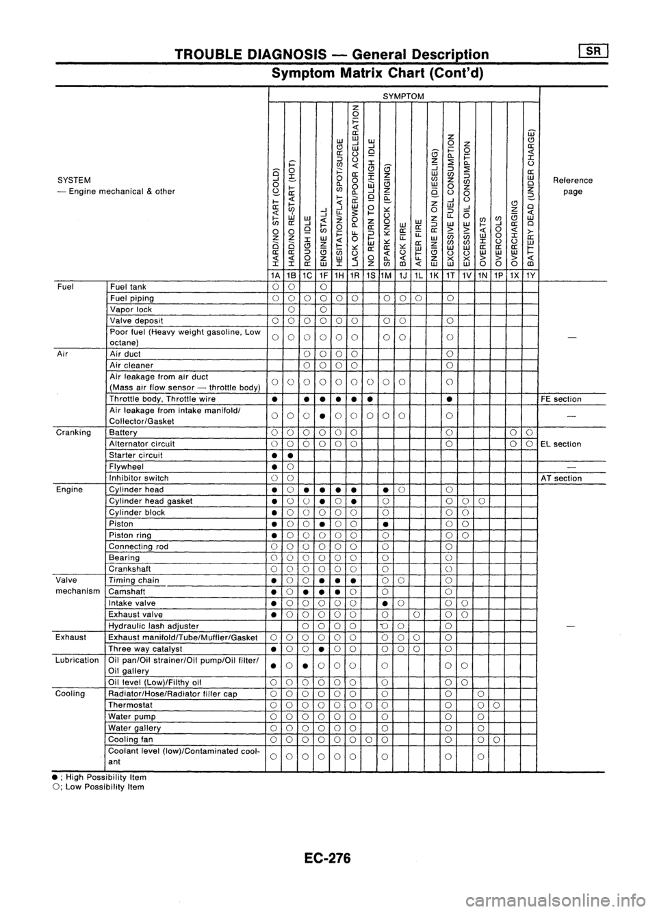
TROUBLEDIAGNOSIS -General Descrip_tio_n
1s_R_1
Symptom MatrixChart(Cont'd)
SYMPTOM
z
0
i=
«
W
a:
z
w
w
w
CJ
CJ
....J
....J
0
Z
a:
w
i=
0
a:
(.)
9
8
«
0.. i=
:I:
::J
(.)
z
:2
i='
en
«
:I:
8
:J
0..
(.)
Q
0
f:::.
CJ
:J
:2
a:
a:
:E
z
w
en
SYSTEM
....J
~
0
0
en
z
:J
w
Reference
0
0..
W
a
w
en
Cl
- Engine mechanical
&
other
I-
en
0
z
0
z
z
S:?-
a: 0..
....J
e-
(.)
0
page
I-
«
l-
ii.
9
~
....J
(.)
2-
a:
~
«
w
0
z
w
CJ
Cl
....J ....J
:.:::
0
:J
....J
Z
«
....J
u.
~
I-
(.)
u..
0
a
«
I-
w
«
Z
0
z
enen
w
en
a:
....J
I-
0..
Z
0
WW
:J
W
W
I-
....J
a:
Cl
0 0
9
en
0
a:
z
a:a:
a:
> >
«
0
«
>-
i=
u..
:J
:.:::
ii:
enen
0
:I:
Z Z
W
0
l-
ii:
w w
a:
Ci Ci
:I:
Z
«
w
:.:::
a:
z
en
en
:I:
(.)
(.)
w
CJ
a
I-
:.:::
a:a:
:.:::
w
a
w
w
a:
a:a:
~
a:
a:
:J
en
(.)
«
(.)
I-
(.)
(.)
w
w
w
« «
0
z
w
«
0
0..
«
u..
Z
x x
>>>
«
:I: :I:
a:
w
:I:
....J
Z
en
(l)
«
w w
w
00 0
(l)
1A 1B
1C 1F1H
1R 1S
1M 1J1L1K
1T
1V
1N
1P1X 1Y
Fuel Fueltank
00 0
Fuel piping
00 0000 000
0
Vapor lock
00
Valve deposit
000 000 00 0
Poor fuel(Heavy weightgasoline. Low
0000 00 00
0
-
octane)
Air Airduct
00 00 0
Air cleaner
0
0
00 0
Air leakage fromairduct
00 00 00 0
0 0
0
(Mass airflow sensor -throttle body)
Throttle body.Throttle wire
•
•
•
•
• •
•
FE
section
Air leakage fromintake
manifoldl
00 0
•
0
0 0
00 0
-
Coliector/Gasket
Cranking Battery
0
0
00 0
0 0
0
0
Alternator circuit
00
00
0
0 0
00
EL
section
Starter circuit
••
Flywheel
•
0
-
Inhibitor switch
00
ATsection
Engine Cylinderhead
•
0
•
•
••
•
0
0
Cylinder headgasket
•
0
()
•
0
•
0
0
00
Cylinder block
•
0
()
0 00 0 00
Piston
•
0
0
•
0
0
•
0
0
Piston ring
•
0
00 0
0 0 00
Connecting rod
00 00
00 0 0
Bearing
000 000 0
0
Crankshaft
00
0 0
0
0 0
0
Valve Timingchain
•
0
0
••
•
0
0 0
mechanism Camshaft
•
0
•• •
0
0 0
Intake valve
•
0
00 0
0
•
0
0
0
Exhaust valve
•
0
00 00 0000
Hydraulic lashadjuster
0000
'0
0 0
-
Exhaust Exhaust
manifoldlTube/Mulfler/Gasket
00
00 0
0
00
0 0
Three waycatalyst
•
0
0
•
0
0 000 0
Lubrication Oilpan/Oil strainer/Oil pump/Oilfilterl
000
0
0 0
0
Oil gallery
••
Oil level (Low)/Filthy oil
00 0000
0 0
0
Cooling Radiator/Hose/Radiator fillercap
00
0 00
0 0 00
Thermostat
00
00 0
0 00 0
00
Water pump
000 000 0 0
0
Water gallery
00 00 00
0 0
0
Cooling fan
00 0
00
0 0
0 0
0
0
Coolant level(low)/Contaminated cool-
00
0000
0 0
0
ant
• ;High Possibility Item
0; Low Possibility Item
EC-276
Page 996 of 1701
TROUBLEDIAGNOSIS -General Description
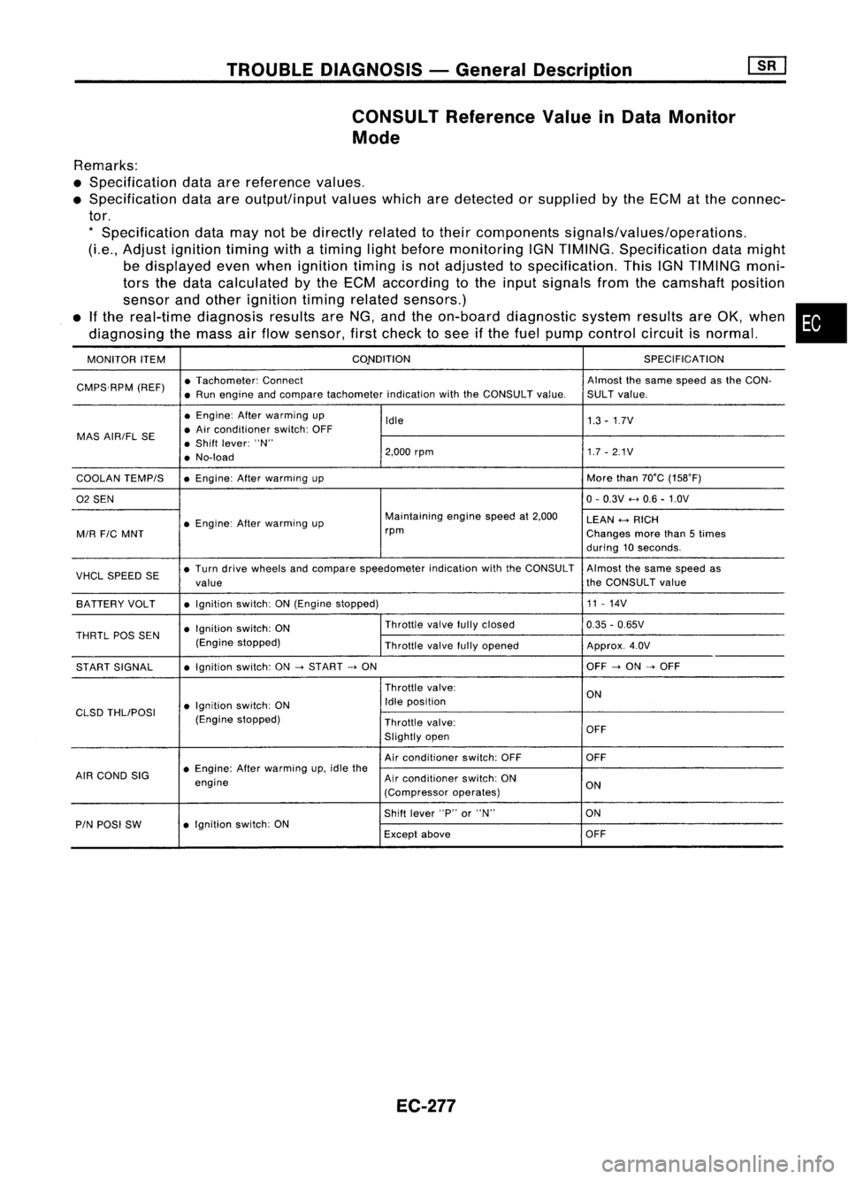
CONSULT Reference ValueinData Monitor
Mode
Remarks:
• Specification dataarereference values.
• Specification dataareoutput/input valueswhicharedetected orsupplied bythe ECM atthe connec-
tor.
*
Specification datamaynotbedirectly relatedtotheir components signals/values/operations.
(Le., Adjust ignition timingwithatiming lightbefore monitoring IGNTIMING. Specification datamight
be displayed evenwhen ignition timingisnot adjusted tospecification. ThisIGNTIMING moni-
tors thedata calculated bythe ECM according tothe input signals fromthecamshaft position
sensor andother ignition timingrelated sensors.)
• Ifthe real-time diagnosis resultsareNG, andtheon-board diagnostic systemresultsareOK, when •
diagnosing themass airflow sensor, firstcheck tosee ifthe fuel pump control circuitisnormal.
MONITOR ITEM CONDITION
SPECIFICATION
CMPS.RPM (REF)•
Tachometer: Connect Almostthesame speed asthe CON-
• Run engine andcompare tachometer indicationwiththeCONSULT value.SULTvalue.
• Engine: Afterwarming up
Idle 1.3-1.7V
MAS AIR/FL SE •
Air conditioner switch:OFF
• Shift lever: "N"
• No-load 2,000
rpm 1.7-2.1V
COOLAN TEMPIS •
Engine: Afterwarming up More
than70°C (15S0F)
02 SEN 0-
0.3V .....0.6 -1.0V
• Engine: Afterwarming up Maintaining
enginespeedat2,000
LEAN
+-->
RICH
MIR
FIC
MNT rpm
Changesmorethan5times
during 10seconds.
VHCL SPEED SE•
Turn drive wheels andcompare speedometer indicationwiththeCONSULT Almostthesame speed as
value the
CONSULT value
BATTERY VOLT •
Ignition switch:ON(Engine stopped) 11
-14V
• Ignition switch:ON Throttle
valvefullyclosed
0.35-0.65V
THRTL
pas
SEN
(Enginestopped)
Throttlevalvefullyopened Approx.4.0V
START SIGNAL •
Ignition switch:ON
->
START
->
ON OFF
->
ON
->
OFF
Throttle valve:
ON
• Ignition switch:ON Idle
position
CLSD THLIPOSI
(Enginestopped)
Throttlevalve:
Slightly open OFF
Air conditioner switch:OFF OFF
AIR COND SIG •
Engine: Afterwarming up,idle the
engine Air
conditioner switch:ON
ON
(Compressor operates)
Shift lever "P"or"N" ON
PIN POSI SW •
Ignition switch:ON
Exceptabove OFF
EC-277
Page 1002 of 1701
TROUBLEDIAGNOSIS -General Description
[ill
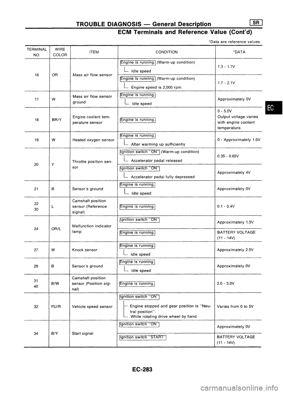
ECM Terminals andReference Value(Conl'd)
*Data arereference values.
TERMINAL WIRE
NO. COLOR ITEM
CONDITION *DATA
IEngine isrunning.1 (Warm-up condition)
1.3-1.7V
L
Idle speed
16 OR Mass
airflow sensor
IEngineisrunning.1 (Warm-up condition)
1.7-2.1V
L
Engine speedis2,000 rpm.
17 W Mass
airflow sensor IEngine
isrunning.!
ApproximatelyOV
ground
L
Idle speed
0-5.0V
18 BRIY Engine
coolant tem-
IEngineisrunning.! Output
voltage varies
perature sensor with
engine coolant
temperature.
19 W
Heatedoxygen sensor IEngine
isrunning.1
0-Approximately 1.OV
L
After warming upsufficiently
Ilgnition switch"ON"I(Warm-up condition)
0.35-0.65V
Throttle position sen-
L
Accelerator pedalreleased
20 Y
sor Ilgnitionswitch"ON"I
L
Approximately
4V
Accelerator pedalfullydepressed
21 B Sensor'sground IEngine
isrunning.1
ApproximatelyOV
L
Idle speed
22 Camshaft
position
30 L
sensor
(Reference IEngineisrunning.1 0.1
-O.4V
signal)
jlgnitionswitch"ON"!
Approximately1.5V
24 ORIL Malfunction
indicator
lamp IEngineisrunning.1 BATTERY
VOLTAGE
(11 -14V)
27 W Knock
sensor IEngine
isrunning.1
Approximately2.5V
L
Idle speed
29 B Sensor's
ground IEngine
isrunning.1
ApproximatelyOV
L
Idle speed
31 Camshaft
position
40
S/W
sensor
(Position sig-
IEngineisrunning.! 2.0
-3.0V
nal)
Ilgnitionswitch"ON"I
32 PUIR
Vehiclespeedsensor
t
Eng;ne "opped andge., po,;!;on ;,"Neo-
Variesfrom0to 5V
tral position".
While rotating drivewheel byhand
Ilgnition switch"ON"!
ApproximatelyOV
34
BIY
Start
signal
Ilgnitionswitch"START"I SA
TTERY VOLTAGE
(11 -14V)
EC-283
•
Page 1003 of 1701
![NISSAN ALMERA N15 1995 Service Manual TROUBLEDIAGNOSIS -General Description
[]:KJ
ECM Terminals andReference Value(Cont'd)
*Data arereference values.
TERMINAL WIRE
ITEM CONDITION *
DATA
NO. COLOR
/Ignitionswitch"ON'"
t NISSAN ALMERA N15 1995 Service Manual TROUBLEDIAGNOSIS -General Description
[]:KJ
ECM Terminals andReference Value(Cont'd)
*Data arereference values.
TERMINAL WIRE
ITEM CONDITION *
DATA
NO. COLOR
/Ignitionswitch"ON'"
t](/manual-img/5/57349/w960_57349-1002.png)
TROUBLEDIAGNOSIS -General Description
[]:KJ
ECM Terminals andReference Value(Cont'd)
*Data arereference values.
TERMINAL WIRE
ITEM CONDITION *
DATA
NO. COLOR
/Ignitionswitch"ON'"
t
"N" or"P" position
(A/T)
OV
35
G/OR
Neutral
position
Neutralposition
(M/T)
switch/lnhibitor switch
I'gnitionswitch"ON"I
BATTERYVOLTAGE
L
Except theabove gearposition (11
-14V)
I'gnition switch"OFF"I
OV
36 B/R Ignition
switch
Ilgnitionswitch"ON"I BATTERY
VOLTAGE
(11 -14V)
37 P/L Throttle
position sen-
pgnition switch"ON"I
Approximately5V
sor power supply
38 Powersupply forECM
Ilgnition switch"ON"I BATTERY
VOLTAGE
47 W/R
(11-14V)
39 B ECCSground IEngine
isrunning.1
Engineground
L
Idle speed
IEngine isrunning.!
L
Both airconditioner switchandblower fanApproximately
OV
41 G Air
conditioner switch switch
are"ON".
IEngine isrunning.1
BATTERYVOLTAGE
L
Airconditioner switchis"OFF". (11
-14V)
IEngine isrunning.1
OV
Power steering oil
L
Steering wheelisbeing turned.
43 PUlW
pressureswitch
IEngineisrunning.1
L
Steering wheelisnot being turned. 7
-9V
46 W/L Power
supply
I'gnitionswitch
"0FFj
BATTERY
VOLTAGE
(Back-up) (11-14V)
48 B ECCSground IEngine
isrunning.1
Engineground
L
Idle speed
109 W/L Currentreturn
Ilgnitionswitch"OFF"I BATTERY
VOLTAGE
(11 -14V)
101 RIB InjectorNo.1
103
G/B
InjectorNo.3
BATTERYVOLTAGE
110 Y/B InjectorNO.2 IEngine
isrunning.1
(11-14V)
112 LIB InjectorNO.4
EC-284
Page 1028 of 1701
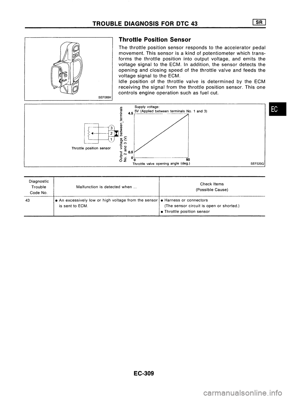
TROUBLEDIAGNOSIS FORDTC43
SEF089K Throttle
Position Sensor
The throttle position sensorresponds tothe accelerator pedal
movement. Thissensor isakind ofpotentiometer whichtrans-
forms thethrottle position intooutput voltage, andemits the
voltage signaltothe ECM. Inaddition, thesensor detects the
opening andclosing speedofthe throttle valveandfeeds the
voltage signaltothe ECM.
Idle position ofthe throttle valveisdetermined
by
the ECM
receiving thesignal fromthethrottle position sensor.Thisone
controls engineoperation suchasfuel cut.
•
SEF520Q
VI
Supplyvoltage:
~ 4.55V (Applied be~VoIee~_terminals NO.1and3)
.~
2
[f~.. ~
L
L
1
&c
~ ~M
Throttle position sensor g
-g
:; ~ 0.5
0.
8 ~
00 -~---_. 90
Throttle valveopening angle(deg.)
Diagnostic Trouble
Code No. Malfunction
isdetected when... Check
Items
(Possible Cause)
43
•
An excessively loworhigh voltage fromthesensor •Harness orconnectors
is sent toECM. (Thesensor circuitisopen orshorted.)
• Throttle position sensor
EC-309
Page 1029 of 1701
TROUBLEDIAGNOSIS FORDTC43
Throttle Position Sensor(Cont'd)
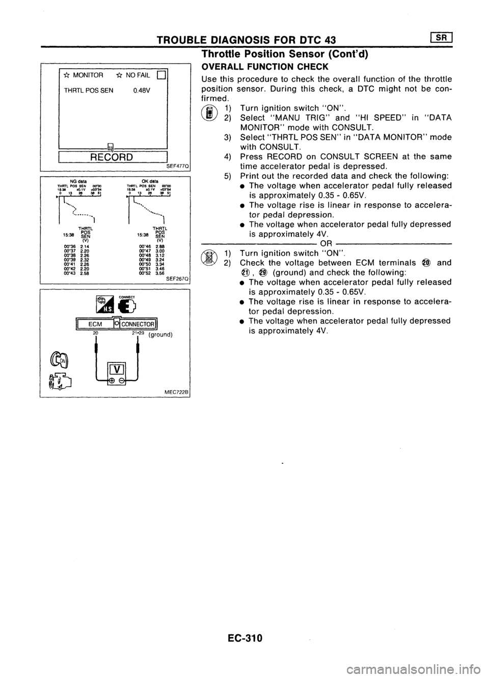
OVERALL FUNCTION CHECK
"*
MONITOR *NO FAIL
0
THRTL
pas
SEN 0.48V
I- I~-----..l
~-R-E-CO-R-D-~I
SEF477QUse
thisprocedure tocheck theoverall function ofthe throttle
position sensor.Duringthischeck, aDTC might notbecon-
firmed.
rij\
1)
~ 2)
Turn
ignition switch"ON".
Select "MANU TRIG"and"HISPEED" in"DATA
MONITOR" modewithCONSULT.
3) Select "THRTL POSSEN" in"DATA MONITOR" mode
with CONSULT.
4) Press RECORD onCONSULT SCREENatthe same
time accelerator pedalisdepressed.
5) Print outthe recorded dataandcheck thefollowing:
• The voltage whenaccelerator pedalfullyreleased
is approximately 0.35-0.65V .
• The voltage riseislinear inresponse toaccelera-
tor pedal depression .
• The voltage whenaccelerator pedalfullydepressed
is approximately 4V.
---------- OR----------
1) Turn ignition switch"ON",
2) Check thevoltage between ECMterminals
@J
and
@,
@
(ground) andcheck thefollOWing:
• The voltage whenaccelerator pedalfullyreleased
is approximately 0.35-0.65V.
• The voltage riseislinear inresponse toaccelera-
tor pedal depression.
• The voltage whenaccelerator pedalfullydepressed
is approximately 4V,
THRTL
15:38 ~~~
(V)
00"46 2.88
00"47 3.00
00"48 3.12
00"49 3.24
00"50 3.34
00"51 3.46
00"52 3.56
SEF267Q
OK
data
THRTL
pos
SEN
OO~
~~~'3. 1
'g;v :":'
................. 1
MEC7228
~i)
ECM
El'coNNEcTORII
LelJ
(9"oodl
II
THRTl
15:38 ~~~
(V)
00"36 214
00"37 2.20
00"38 2.26
00"39 2.32
00"41 2.26
00"42 2.20
00"43 2.58
NG
data
THFm.
pos
SEN 00"00
'~U. '3
~v ~:'
•
")
•...•..•..• 1
EC-310
Page 1030 of 1701
~@
TROUBLE
DIAGNOSIS FORDTC43
Throttle Position Sensor(Cont'd)
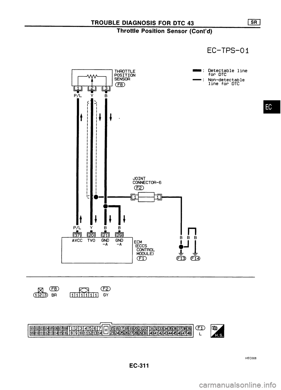
EC-TPS-01
THROTTLE
--
Detectable
line
POSITION for
DTC
SENSOR
-:
Non-detectable
@
line
forDTC
(
1
•
I
I
t
I~
~
I
I
I
I
I
I
I
I
I
I
I
I
I
I
I
I
I
I
JOINT
I
I
CONNECTOR-6
I
I
@
I
I
I I
~~
'::::
.-
t
~
i~.
P/L
Y
B
B
n
13-71 12.01
~
12-91
B
B
B
AVCC TVOGNDGND
ECM
t
J
1
-A
-A
(ECCS
CONTROL
MODULE)
CED
0:13)
m
~@
IIIillIIIIIIl
GY
CED
L
HECOOB
EC-311
Page 1031 of 1701
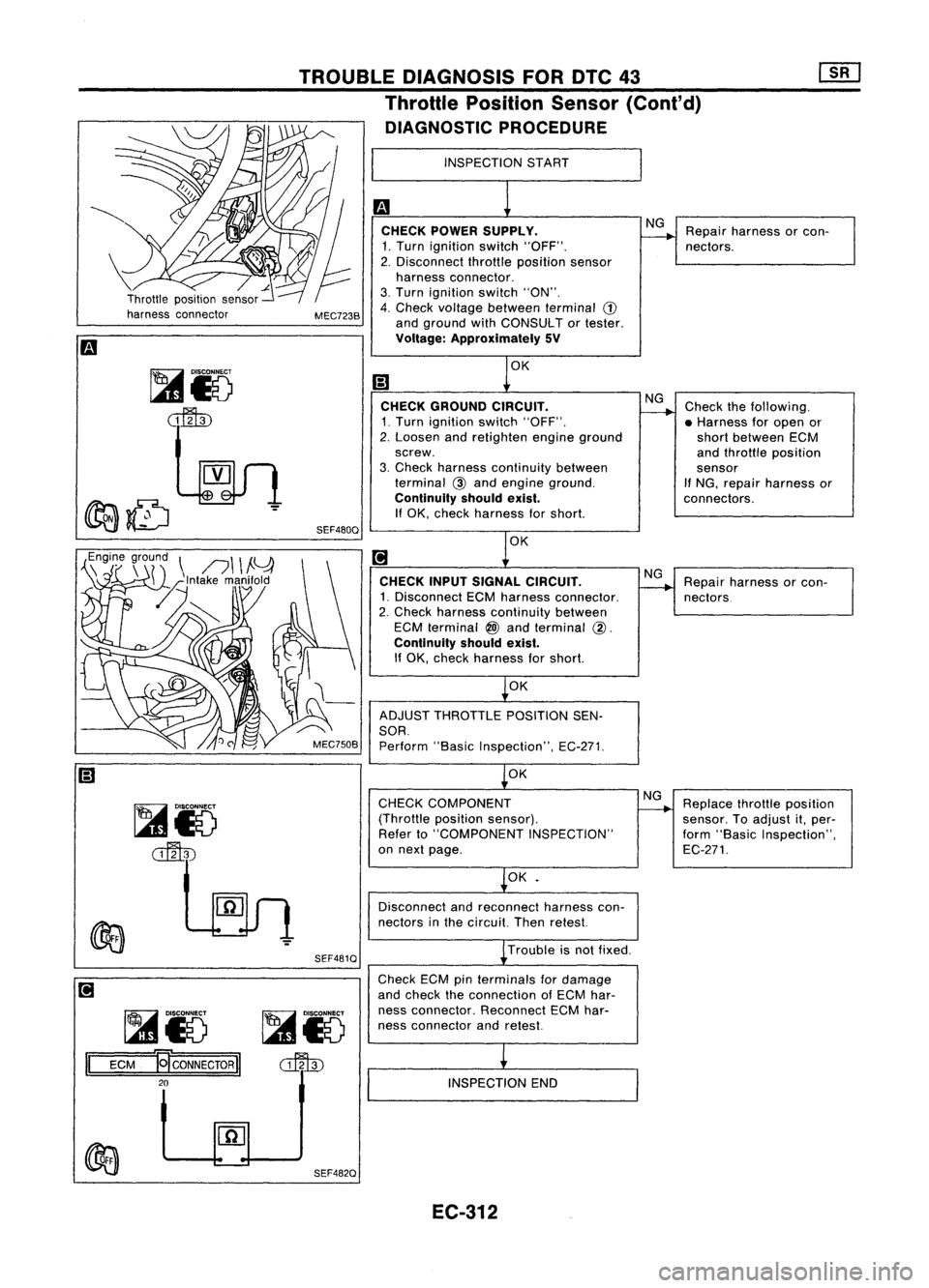
Repairharness orcon-
nectors.
NG
CHECK POWER SUPPLY.
1. Turn ignition switch"OFF".
2. Disconnect throttleposition sensor
harness connector.
3. Turn ignition switch"ON".
4. Check voltage between terminal
(1)
and ground withCONSULT ortester.
Voltage: Approximately 5V
INSPECTION
START
TROUBLE
DIAGNOSIS FORDTC43
Throttle Position Sensor(Cont'd)
DIAGNOSTIC PROCEDURE
MEC723B
,,~n~7
r~r~\
n\ \
!Y
-z~lntake manifold
[L~
SEF480QOK
CHECK GROUND CIRCUIT.
1. Turn ignition switch"OFF".
2. Loosen andretighten engineground
screw.
3. Check harness continuity between
terminal
@
and engine ground.
Continuity shouldexist.
If
OK, check harness forshort.
OK
CHECK INPUTSIGNAL CIRCUIT.
1. Disconnect ECMharness connector.
2. Check harness continuity between
ECM terminal
@)
and terminal
@.
Continuity shouldexist.
If OK, check harness forshort.
OK
ADJUST THROTTLE POSITIONSEN-
SOR.
Perform "BasicInspection", EC-271.
OK NG
NG
Check
thefollowing.
• Harness foropen or
short between ECM
and throttle position
sensor
If
NG, repair harness or
connectors.
Repair harness orcon-
nectors
~io
~ SEF481Q
CHECK
COMPONENT
(Throttle positionsensor).
Refer to"COMPONENT INSPECTION"
on next page.
OK•
Disconnect andreconnect harnesscon-
nectors inthe circuit. Thenretest.
Trouble isnot fixed.
NG
Replace throttleposition
sensor. Toadjust it,per-
form "Basic Inspection",
EC-271.
~io ~i5
II
ECM
~CONNECTORII
o::fl\])
20
Check
ECMpinterminals fordamage
and check theconnection ofECM har-
ness connector. Reconnect ECMhar-
ness connector andretest.
INSPECTION END
SEF482Q EC-312