Page 1149 of 1701
ENGINECOOLING SYSTEM
Water HoseDrawing (Cont'd)
GA16DE withVTCforAustralia
Intakemanifold
5
9
•
Q)
Intake manifold toThermostat
housing (upper)
@
Intake manifold toThermostat
housing (lower)
@
Water jacket toWater pipe
lower
@
Water pipelower
CID
Water pipelower toThrottle
body
@
Water pipelower toIntake
manifold
(J)
Water pipeupper
LC-11 @
Throttle bodytoWater pipe
upper
@
Intake manifold toWater pipe
upper
@
Water pipeupper toThermostat
housing
SLC021BA
Page 1189 of 1701
OUTERCOMPONENT PARTS
tOJ:
N.m (kg-m, ft-Ib)
iii :
N'm (kg-m, in-Ib)
Tighten innumerical order.
Engine
A
Iront
y
*
Throttle bodyboltstightening procedure
1) Tighten allbolts to9to 11 N.m (0.9 to
1.1
kg-m, 6.5to8.0 fl-Ib)
2) Tighten allbolts to18 to22 N'm (1.8to2.2 kg-m, 13to16 ft-Ib)
Tighten innumerical order.
GA16DE
WITHOUT VTe,14DE AND15DE
SEC. 140-147-163-164
GA15DE
SEM220F
CD
Throttle position sensor
@ Mass airflow sensor
@
IACV-AAC valve
@ IACV-FICD solenoidvalve
@ Throttle body @
Engine coolant temperature
sensor
IJ)
Airrelief plug
@
Injector
@ Injector tube
@l
Pressure regulator
@
EGR valve (GA15DE
M/T
model only)
@ Intake manifold
@ IACV-AAC valve(GA15DE
engine models only)
EM-10
Page 1191 of 1701
GA16DEWITHVTC
SEC. 140.163.164
~ 1st.
7.85 •10.8
(0.8. 1.1,5.8.8.0)
G)
Intake manifold collector
@
Gasket
@
Throttle body
OUTER
COMPONENT PARTS
@
Collector gasket
@
Fuelgallery assembly
@
Insulator
EM-12
(J)
Pressure regulator
@
Intake manifold gasket
@
Intake manifold
SEM064FB
Page 1192 of 1701
OUTERCOMPONENT PARTS
Tightening order
*
Intake manifold collector boltstightening order
Tighten innumerical order.
*Intake
manifold boltsandnuts tightening order
Tighten innumerical order.
•
*Throttle bodybolts tightening procedure
1) Tighten allbolts to8.8 to10.8 N.m (0.90 to1.10 kg-m, 6.5to8.0 ft-Ib)
2) Tighten allbolts to17.7 to21.6 N.m (1.81 to2.20 kg-m, 13.06to15.93 ft-Ib)
• Make surethedirection ofthe gasket isas shown infigure.
Tighten innumerical order
EM-13
o
,,-0
Gasket
o
SEM066FB
Page 1194 of 1701

COMPRESSIONPRESSURE
20
mm
(O.79 In)dls.
Use compressor testerwhose end(rubber
portion) isless than 20mm (0.79 in)dia.
Otherwise, itmay becaught bycylinder
head during removal.
SEM387CMeasurement
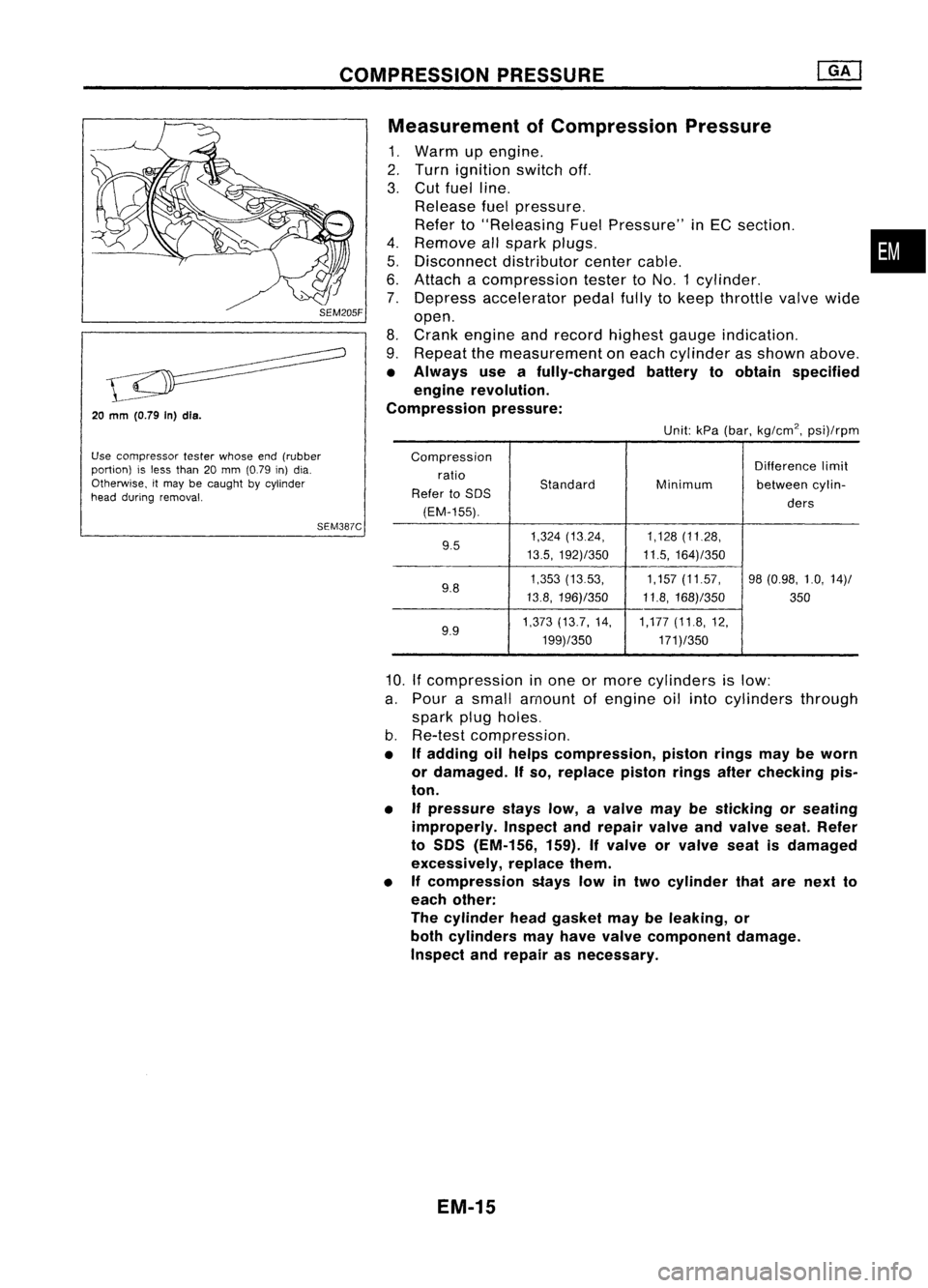
ofCompression Pressure
1. Warm upengine.
2. Turn ignition switchoff.
3. Cut fuel line.
Release fuelpressure.
Refer to"Releasing FuelPressure" inEC section. •
4. Remove allspark plugs.
5. Disconnect distributorcentercable.
6. Attach acompression testertoNO.1 cylinder.
7. Depress accelerator pedalfullytokeep throttle valvewide
open.
8. Crank engine andrecord highest gaugeindication.
9. Repeat themeasurement oneach cylinder asshown above.
• Always useafully-charged batterytoobtain specified
engine revolution.
Compression pressure:
Unit:kPa(bar, kg/cm
2,
psi)/rpm
Compression Differencelimit
ratio
Standard
Refer toSOS Minimum
betweencylin-
(EM-155). ders
9.5 1,324
(13.24, 1,128(11.28,
13.5, 192)/350 11.5,164)/350
9.8 1,353
(1353, 1,157(11.57, 98(0.98, 1.0,14)/
13.8, 196)/350 11.8,168)/350
350
9.9 1,373
(13.7, 14, 1,177(11.8,12,
199)/350 171)/350
10.
If
compression inone ormore cylinders islow:
a. Pour asmall amount ofengine oilinto cylinders through
spark plugholes.
b. Re-test compression,
• Ifadding oilhelps compression, pistonringsmaybeworn
or damaged. Ifso, replace pistonringsafterchecking pis-
ton.
• Ifpressure stayslow,avalve maybesticking orseating
improperly. Inspectandrepair valveandvalve seat.Refer
to SOS (EM-156, 159).Ifvalve orvalve seatisdamaged
excessively, replacethem.
• Ifcompression stayslowintwo cylinder thatarenext to
each other:
The cylinder headgasket maybeleaking, or
both cylinders mayhave valve component damage.
Inspect andrepair asnecessary.
EM-15
Page 1239 of 1701
OUTERCOMPONENT PARTS
SEC.
to
18
to
22
N'm
(1.8
to
2.2 kg-m,
Tighten innumerical order.13to16ft-Ib).
~
2.9.3.8
(0.30 -0.39,
26.0 -33.9.)
1
I
{O.,'OgO
J{"ogO
?
~ ;N'm (kg-m, ft-Ib)
~ :N.m (kg-m, in-Ib)
SEM232F
G) Injector
@
Pressure regulator
@
Intake manifold
@ EGR tube
@ EGR valve
@
EGRC-BPT valve
(J) Intake manifold collector
@ Rod
@ Accel-drum unit
@)
Throttle position sensor
EM-60 @
Throttle body
@
IACV-air regulator
@
IACV-AAC valve
@
IACV-FICD solenoidvalve
Page 1241 of 1701

COMPRESSIONPRESSURE
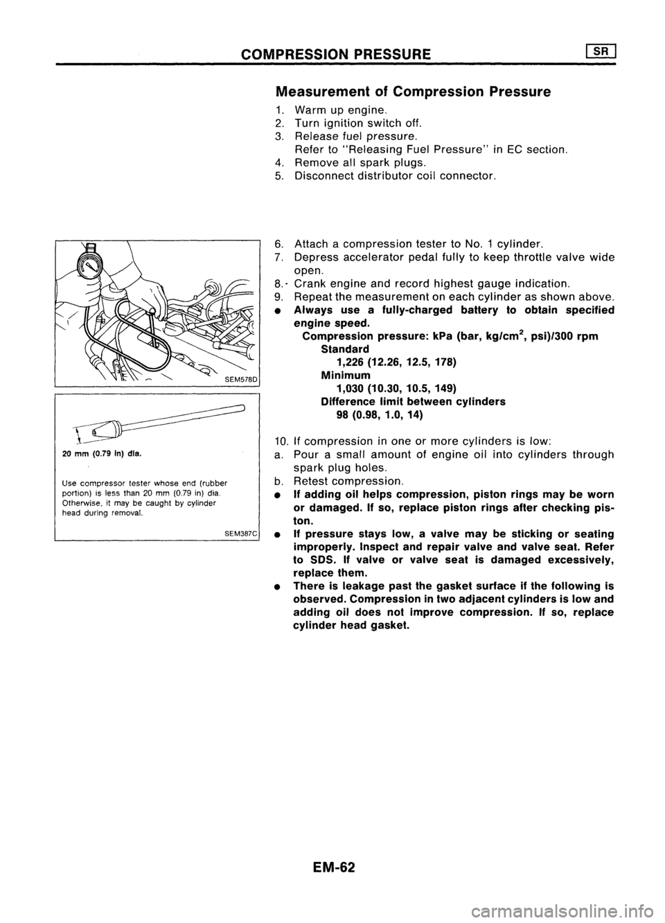
Measurement ofCompression Pressure
1. Warm upengine.
2. Turn ignition switchoff.
3. Release fuelpressure.
Refer to"Releasing FuelPressure" inEC section.
4. Remove allspark plugs.
5. Disconnect distributorcoilconnector.
20
mm (0.79
In)dls.
Use compressor testerwhose end(rubber
portion) isless than 20mm (0.79 in)dia.
Otherwise. itmay becaught bycylinder
head during removal.
SEM387C6.
Attach acompression testertoNO.1 cylinder.
7. Depress accelerator pedalfullytokeep throttle valvewide
open.
8.' Crank engine andrecord highest gaugeindication.
9. Repeat themeasurement oneach cylinder asshown above.
• Always useafully-charged batterytoobtain specified
engine speed.
Compression pressure:kPa(bar, kg/cm
2,
psi)/300 rpm
Standard 1,226 (12.26, 12.5,178)
Minimum 1,030 (10.30, 10.5,149)
Difference limitbetween cylinders
98 (0.98, 1.0,14)
10. Ifcompression inone ormore cylinders islow:
a. Pour asmall amount ofengine oilinto cylinders through
spark plugholes.
b. Retest compression.
• If
adding oilhelps compression, pistonringsmaybeworn
or damaged.
If
so, replace pistonringsafterchecking pis-
ton.
• Ifpressure stayslow,avalve maybesticking orseating
improperly. Inspectandrepair valveandvalve seat.Refer
to
50S.
If
valve orvalve seatisdamaged excessively,
replace them.
• There isleakage pastthegasket surface ifthe following is
observed. Compression intwo adjacent cylinders islow and
adding oildoes notimprove compression.
If
so, replace
cylinder headgasket.
EM-62
Page 1263 of 1701

..:;:r--
Coupling
Ii!
Grease
Rod
Throttle body
Coupling
LCOUPJing
~ 9
Ii!
Grease ~
When closed 4a'"link
SEM205D
Tr;rn ~Adjusting serew
_ /- Aeeel-drum
"""7'i'i\.
Stopperlever
SEM208D ACCEL-DRUM
UNIT
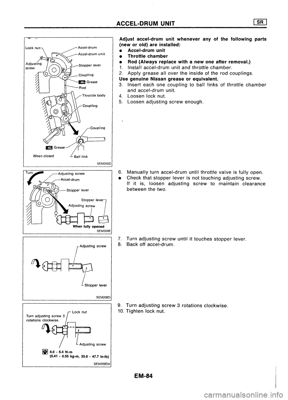
Adjust accel-drum unitwhenever anyofthe following parts
(new orold) areinstalled:
• Accel-drum unit
• Throttle chamber
• Rod (Always replacewithanew oneafter removal.)
1. Install accel-drum unitand throttle chamber.
2. Apply grease allover theinside ofthe rod couplings .
Use genuine Nissangrease orequivalent.
3. Insert eachonecoupling toball links ofthrottle chamber
and accel-drum unit.
4. Loosen locknut.
5. Loosen adjusting screwenough.
6. Manually turnaccel-drum untilthrottle valveisfully open.
• Check thatstopper leverisnot touching adjusting screw.
If itis, loosen adjusting screwtomaintain clearance
between thetwo.
7. Turn adjusting screwuntil
it
touches stopperlever.
8. Back offaccel-drum.
Turn adjusting screw3
rotations clockwise. Lock
nut 9.
Turn adjusting screw3rotations clockwise.
10. Tighten locknut.
~ 4.0-5.4 N.m
(0.41 -0.55 kg-m, 35.6-47.7 In-rb)
SEM209DA
EM-84