1995 NISSAN ALMERA N15 pcv valve
[x] Cancel search: pcv valvePage 750 of 1701
POSITIVECRANKCASE VENTILATION
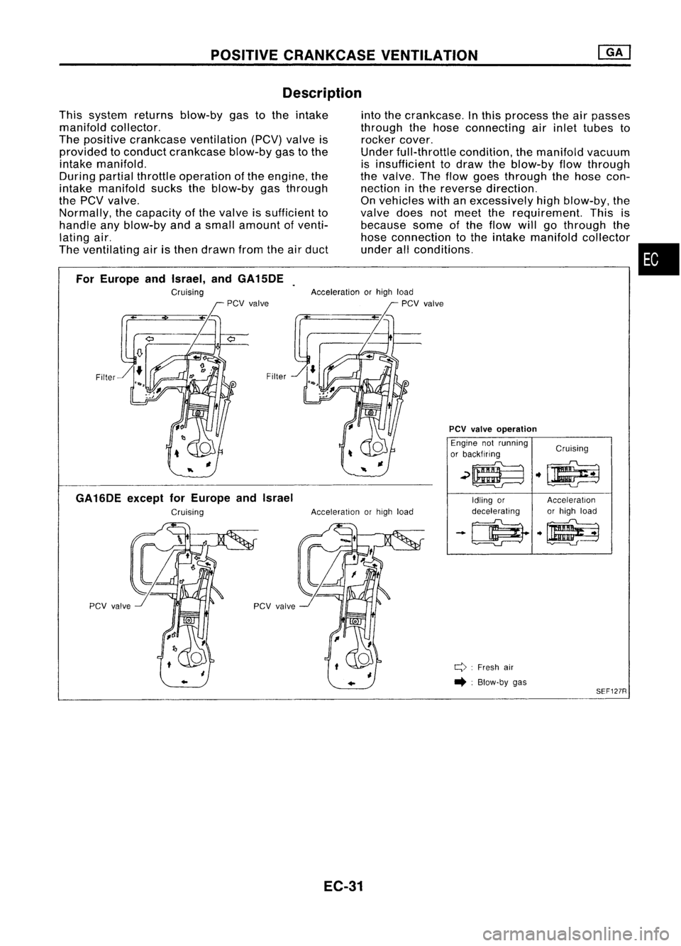
Description
intothecrankcase. Inthis process theairpasses
through thehose connecting airinlet tubes to
rocker cover.
Under full-throttle condition,themanifold vacuum
is insufficient todraw theblow-by flowthrough
the valve. Theflow goes through thehose con-
nection inthe reverse direction.
On vehicles withanexcessively highblow-by, the
valve doesnotmeet therequirement. Thisis
because someofthe flow willgothrough the
hose connection tothe intake manifold collector
under allconditions.
This
system returnsblow-by gastothe intake
manifold collector.
The positive crankcase ventilation (peV)valveis
provided toconduct crankcase blow-bygastothe
intake manifold.
During partialthrottle operation ofthe engine, the
intake manifold suckstheblow-by gasthrough
the
pev
valve.
Normally, thecapacity ofthe valve issufficient to
handle anyblow-by andasmall amount ofventi-
lating air.
The ventilating airisthen drawn fromtheairduct
•
SEF127R
Q:
Fresh air
• :Blow-by gas
PCV
valve
operation
Engine notrunning
Cruising
or backfiring
~~ .~
Idling or Acceleration
decelerating or
high load
-~ .~
..
Acceleration
orhigh load
Acceleration
orhigh load
pcv valve
Filter
For
Europe andIsrael, andGA15DE
Cruising
GA16DE exceptforEurope andIsrael
Cruising
EC-31
Page 751 of 1701
POSITIVECRANKCASE VENTILATION
Inspection
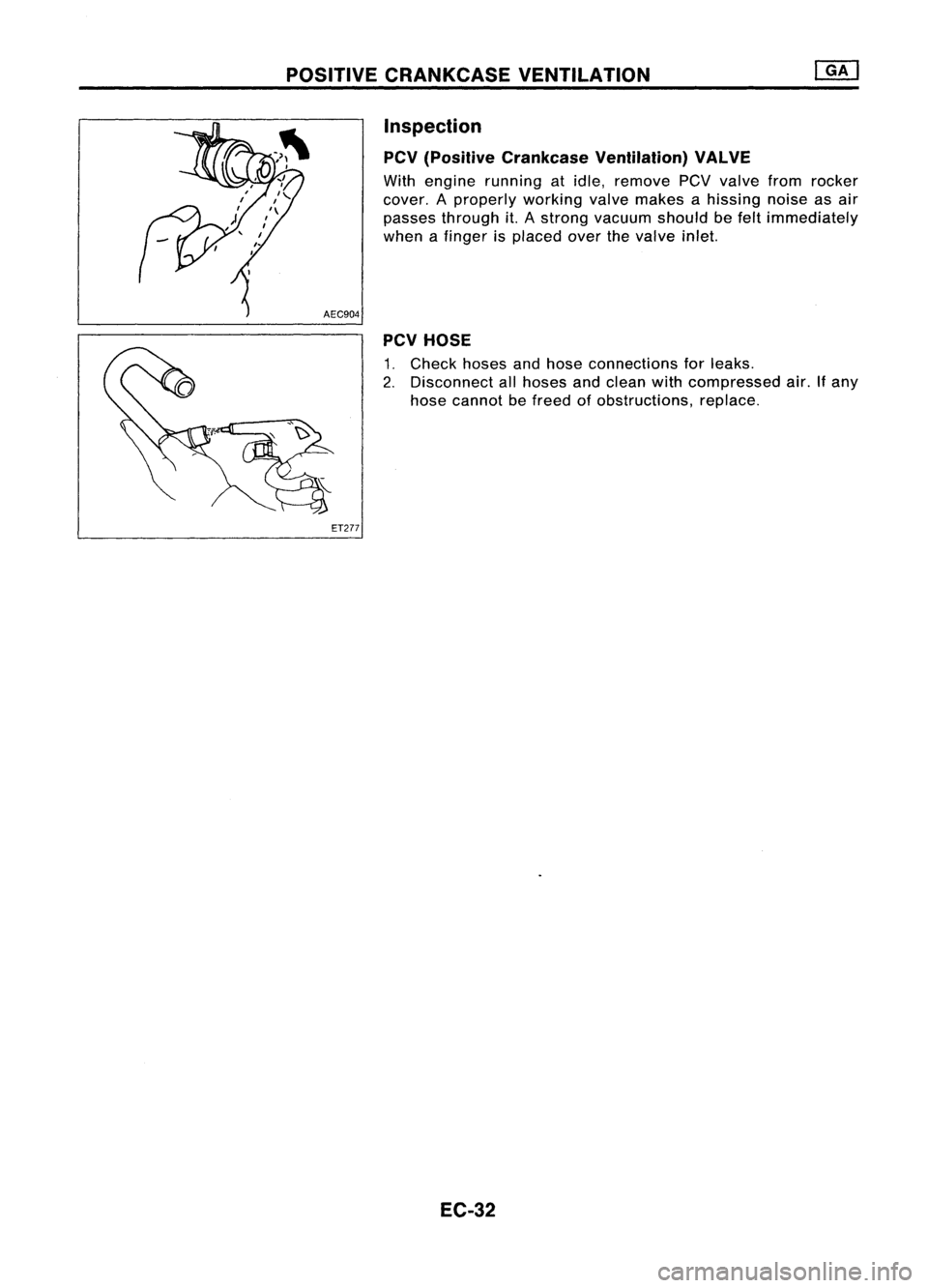
PCV (Positive Crankcase Ventilation) VALVE
With engine running atidle, remove PCVvalve fromrocker
cover. Aproperly workingvalvemakes ahissing noiseasair
passes through it.Astrong vacuum shouldbefelt immediately
when afinger isplaced overthevalve inlet.
AEC904 PCVHOSE
1. Check hosesandhose connections forleaks.
2. Disconnect allhoses andclean withcompressed air.Ifany
hose cannot befreed ofobstructions, replace.
ET277
EC-32
Page 959 of 1701
POSITIVECRANKCASE VENTILATION
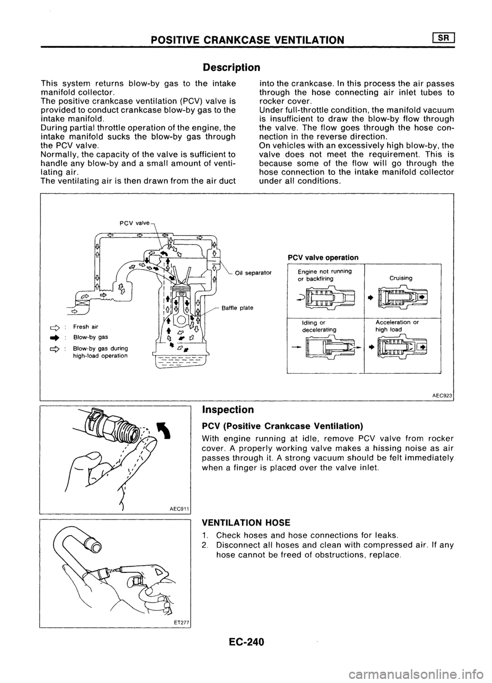
Description
This system returnsblow-by gastothe intake
manifold collector.
The positive crankcase ventilation (PCV)valveis
provided toconduct crankcase blow-bygastothe
intake manifold.
During partialthrottle operation ofthe engine, the
intake manifold suckstheblow-by gasthrough
the
pev
valve.
Normally, thecapacity ofthe valve issufficient to
handle anyblow-by andasmall amount ofventi-
lating air.
The ventilating airisthen drawn fromtheairduct into
thecrankcase. Inthis process theairpasses
through thehose connecting airinlet tubes to
rocker cover.
Under full-throttle condition,themanifold vacuum
is insufficient todraw theblow-by flowthrough
the valve. Theflow goes through thehose con-
nection inthe reverse direction.
On vehicles withanexcessively highblow-by, the
valve doesnotmeet therequirement. Thisis
because someofthe flow willgothrough the
hose connection tothe intake manifold collector
under allconditions.
Oil separator
q
Freshair
.. Blow-by gas
ct>
Blow-by gasduring
high-load operation Baffle
plate
PCV
valve operation
Engine notrunning
or backfiring Cruising
~~
.0
Idling or Acceleration
or
decelerating high
load
-~--
.~
AEC923
Inspection
PCV (Positive Crankcase Ventilation)
With engine running atidle, remove PCVvalve fromrocker
cover. Aproperly workingvalvemakes ahissing noiseasair
passes through it.Astrong vacuum shouldbefelt immediately
when afinger isplaced overthevalve inlet.
AEC911 VENTILATION HOSE
1. Check hosesandhose connections forleaks.
2. Disconnect allhoses andclean withcompressed air.Ifany
hose cannot befreed ofobstructions, replace.
ET277 EC-240
Page 1238 of 1701
OUTERCOMPONENT PARTS
•
SEM231F
SEC.
130-140-150-210-211-221
~ __to:J
13•16 (1.3 -1.6, 9.12)
to:J
16•21 (1.6. 2.1,12. 15)
to:J
20•29
(2.0 •3.0,
14 .22)
to:J
41-52 (4.2 -5.3, 30-38)
~---- D_?
. 'J ~
~~~ 0
-t::;-.....~ /,
0
to:J
21-26 ./"
(2.1. 2.7, ,./"~/'
12 -1~)
fs\
19-~~7
~ to:J
16•21
Q
to:J
18. 21 ,
to:J
45_60 (1.6-2.1, 0
Ii]
6.3 _8.3
(1.8 •2.1, (4.6•6.1, 12•15)
1
(0.64•0.85,
to:J
16•19 13-15)
to:J
16•21 33•44)
(1.6 -1.9, (1.6-2.1,
to:J
16•21
12 -14)
12•15)
t"J
16•,.
f"-~
t"J
15•21
r::!
*
H
...----4lJ
~~'. '1~
J
r \~ ~~'..,:;
1,
~Q.
/¥i-;:
--'Il
1il3.7 -5.0
J~
--A)
to:J
16-21
~11V>/
(0.38 _0.51, A~ - (1.6.2.1,12•15)\...,//
~to:J
20.29(2.0-3.0, 14-22)
33.0 •44.3)
Y
&'/-
:f~l
to:J
20•26 (2.0 •2.7, 14-20)
to:J :
N'm (kg-m, fl-Ib)
to:J
16-21 (1.6 -2.1, 12-15)~/
Ii] :
N'm (kg-m, in-Ib) •
~ :Apply
liquidgasket.
*:
Refer toLC section
("Thermostat", "ENGINECOOLING SYSTEM").
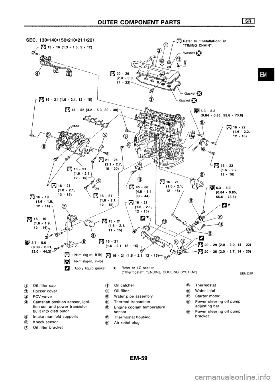
G)
Oilfiller cap
@
Oilcatcher
@
Thermostat
@
Rocker cover
@
Oilfilter
@
Water inlet
@
PCVvalve
@
Water pipeassembly
@
Starter motor
@
Camshaft
positionsensor,igni-
@
Thermal transmitter
@
Power steering oilpump
tion coiland power transistor
@
Engine coolant temperature adjusting
bar
built intodistributor
sensor
@
Power
steering oilpump
@
Intake manifold supports
@
Thermostat housing bracket
@
Knock sensor
@
Airrelief plug
rJ)
Oilfilter bracket
EM-59
Page 1493 of 1701
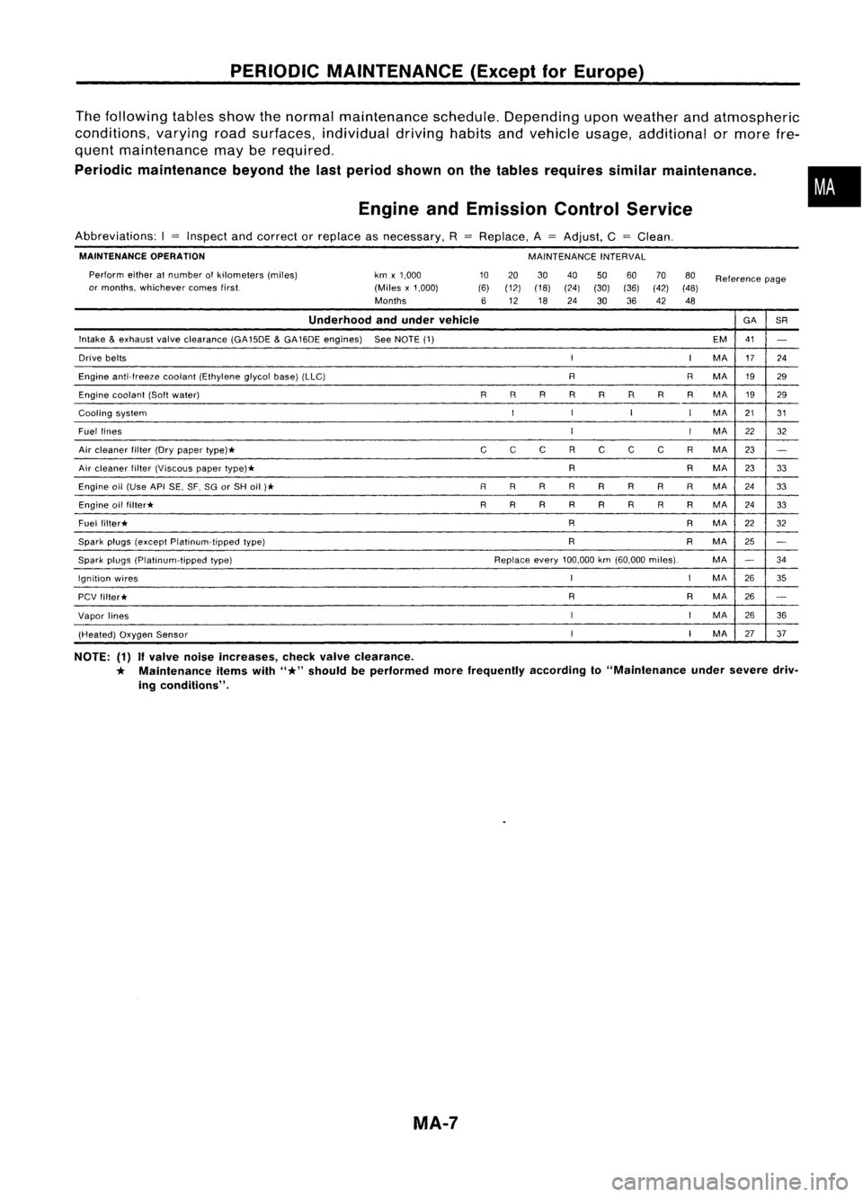
PERIODICMAINTENANCE (ExceptforEurope)
The following tablesshowthenormal maintenance schedule.Depending uponweather andatmospheric
conditions, varyingroadsurfaces, individual drivinghabitsandvehicle usage,additional ormore fre-
quent maintenance mayberequired.
Periodic maintenance beyondthelast period shown onthe tables requires similarmaintenance .
Engine andEmission ControlService
•
Abbreviations: I
=
Inspect andcorrect orreplace asnecessary. R
MAINTENANCE OPERATION
Perform eitheratnumber ofkilometers (miles)
or months, whichever comestirst. km
x1,000
(Miles x1,000)
Months
Replace.
A
=
Adjust, C
=
Clean.
MAINTENANCE INTERVAL
10 20 3040
506070
80
Reference page
(6) (12) (18)
(24)(30)(36)(42)(48)
6 12 18
24
3036
42 48
Underhood andunder vehicle GA
SR
Intake
&
exhaust valveclearance (GA15DE
&
GA16DE engines) SeeNOTE (1)
EM41
-
Drive belts
II
MA 17
24
Engine anti-Ireeze coolant(Ethylene glycolbase)(LLC) RRMA 1929
Engine coolant (Softwater) RRR
R
R R
R
RMA
1929
Cooling system
I
I
I
I
MA 2131
Fuel lines
I
I
MA
22
32
Air cleaner filter(Drypaper type)*
CC
C RC CC RMA 23
-
Air cleaner filter(Viscous papertype)* R
RMA
2333
Engine oil(Use APISE,SF.SGorSH oil)*
R
RRRR R
RR
MA 24
33
Engine oilfilter* R
R R
R
R RRRMA
2433
Fuel filter* R
RMA
22
32
Spark plugs(except Platinum-tipped type) R
RMA
25
-
Spark plugs(platinum-tipped type) Replaceevery100,000 km(60.000 miles). MA
-
34
Ignition wires
I
I
MA
2635
PCV filter* R
RMA
26
-
Vapor lines
I
I
MA
26
36
(Heated) OxygenSensor
I
I
MA 2737
NOTE: (1)
If
valve noiseincreases, checkvalveclearance.
*
Maintenance itemswith
"*"
should beperformed morefrequently accordingto"Maintenance undersevere driv-
ing conditions".
MA-7
Page 1497 of 1701
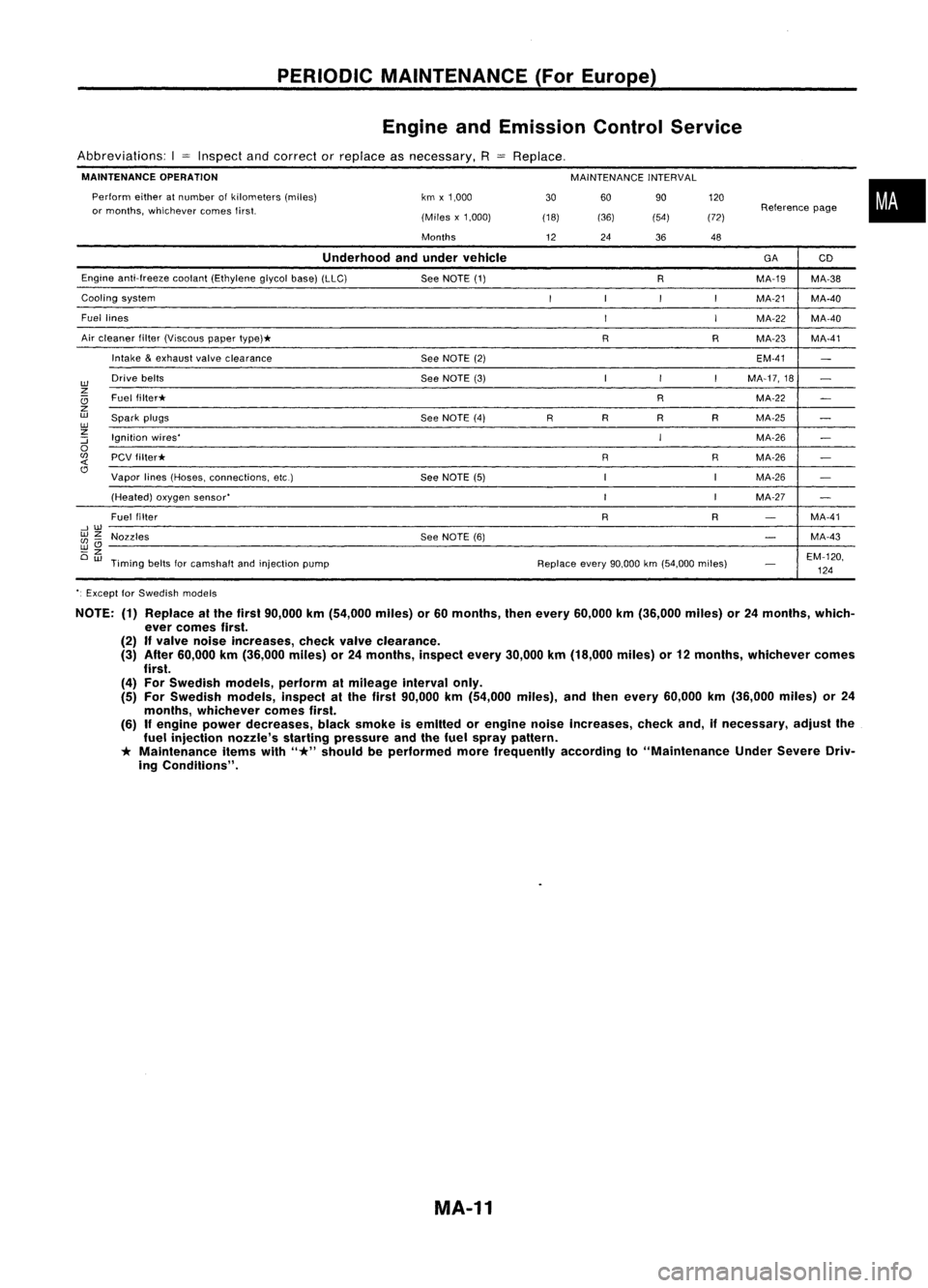
PERIODICMAINTENANCE (ForEurope)
Engine andEmission ControlService
Abbreviations: I
=
Inspect andcorrect orreplace asnecessary,
R
MAINTENANCE OPERATION
MAINTENANCEINTERVAL
60 90
(36) (54)
Perform
eitheratnumber ofkilometers (miles)
or months, whichever comesfirst. km
x1,000
(Miles x1,000)
Months
Replace,
30
(18)
12 24
36120
(72) 48
Reference
page
•
Underhood andunder vehicle
GA
CD
Engine anti-freeze cootant(Ethylene glycolbase)(LLC)
SeeNOTE (1)
RMA-19
MA-38
Cooling system
I
I
I
I
MA-21 MA-40
Fuel lines
I
I
MA-22
MA-40
Air cleaner filter(Viscous papertype)*
RRMA-23 MA-41
Intake
&
exhaust valveclearance
SeeNOTE (2) EM-41
-
w
Drive
belts
SeeNOTE (3) I
I
I
MA-17,18
-
z
Ci
Fuel
filter* RMA-22
-
z
w
Spark plugs
SeeNOTE (4)
RR
RRMA-25
-
w
z
Ignition wires'
IMA-26
:::;
-
0
(fJ
PCVfilter* RRMA-26
-
<{
Cl
Vapor lines(Hoses, connections, etc.)
SeeNOTE (5) IIMA-26
-
(Heated) oxygensensor'
I
IMA-27
-
Fuel filter
RR
-
MA-41
--,w
wz
Nozzles SeeNOTE (6)
-
MA-43
(fJ-
wCl
-z
EM-120,
Ow
Timing beltsforcamshalt andinjection pump Replaceevery90,000 km(54,000 miles)
-
124
'. Except forSwedish models
NOTE: (1)Replace atthe first 90,000 km(54,000 miles)or60 months, thenevery 60,000 km(36,000 miles)or24 months, which-
ever comes first.
(2)
If
valve noise Increases, checkvalveclearance.
(3) After 60,000 km(36,000 miles)or24 months, inspectevery30,000 km(18,000 miles)or12 months, whichever comes
first.
(4) For Swedish models,performalmileage intervalonly.
(5) For Swedish models,inspectalthe first 90,000 km(54,000 miles),andthen every 60,000 km(36,000 miles)or24
months, whichever comesfirst.
(6)
If
engine powerdecreases, blacksmoke isemitted orengine noiseincreases, checkand,ifnecessary, adjustthe
fuel injection nozzle'sstartingpressure andthefuel spray pattern.
*
Maintenance itemswith
"*"
should beperformed morefrequently accordingto"Maintenance UnderSevere Driv-
ing Conditions".
MA-11
Page 1512 of 1701
SMA476
Side
electrode
It, ENGINE
MAINTENANCE ~
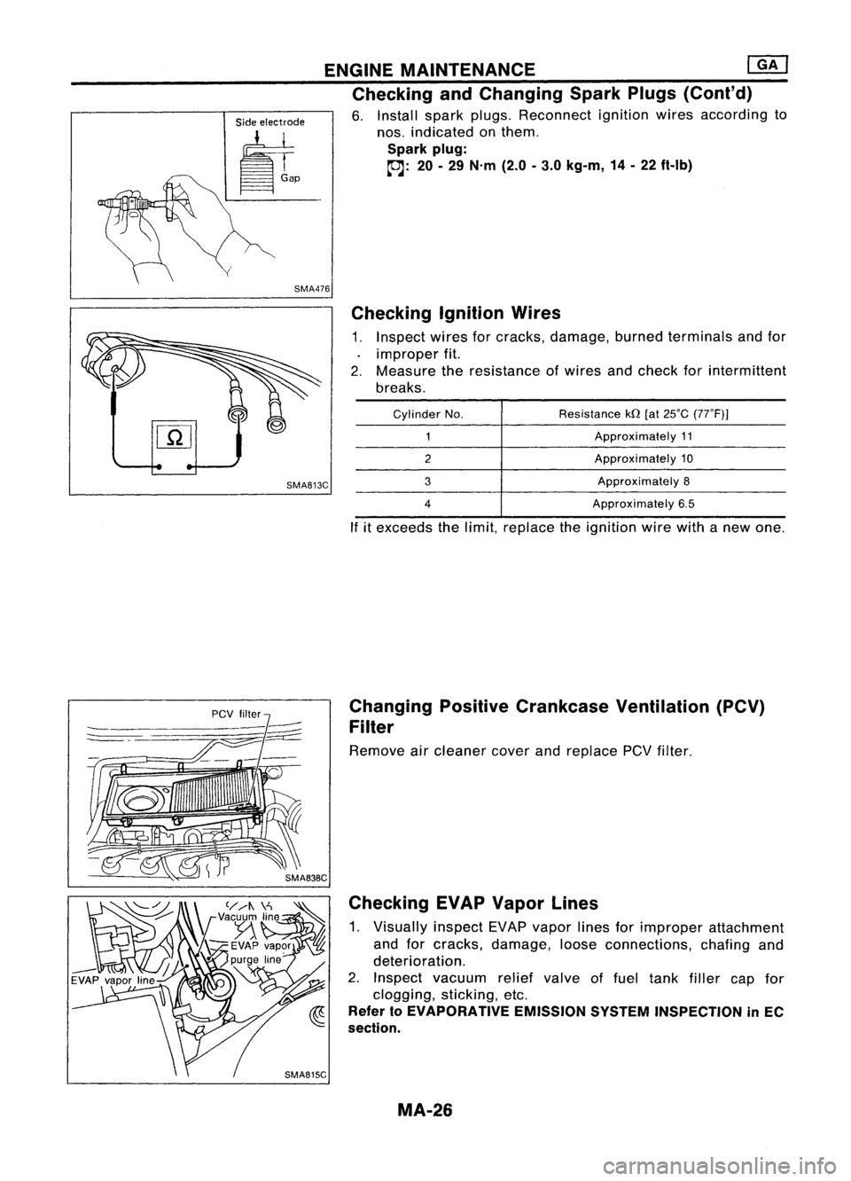
Checking andChanging SparkPlugs(Cont'd)
6. Install sparkplugs. Reconnect ignitionwiresaccording to
nos. indicated onthem.
Spark plug:
~: 20-29 N'm (2.0-3.0 kg-m, 14-22 ft-Ib)
Checking IgnitionWires
1. Inspect wiresforcracks, damage, burnedterminals andfor
improper fit.
2. Measure theresistance ofwires andcheck forintermittent
breaks.
SMA813C
Cylinder
No.
2
3
4
Resistance
kQ[at25'C (77'F)]
Approximately 11
Approximately 10
Approximately 8
Approximately 6.5
If itexceeds thelimit, replace theignition wirewithanew one.
Changing PositiveCrankcase Ventilation (PCV)
Filter
Remove aircleaner coverandreplace
pev
filter.
Checking EVAPVapor Lines
1. Visually inspectEVAPvapor linesforimproper attachment
and forcracks, damage, looseconnections, chafingand
deterioration.
2. Inspect vacuum reliefvalve offuel tank filler capfor
clogging, sticking,etc.
Refer
10
EVAPORATIVE EMISSIONSYSTEMINSPECTION inEC
section.
MA-26