1995 NISSAN ALMERA N15 change time
[x] Cancel search: change timePage 952 of 1701
ENGINEANDEMISSION BASICCONTROL SYSTEMDESCRIPTION
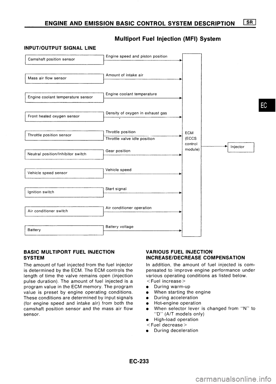
Multiport FuelInjection (MFI)System
INPUT/OUTPUT SIGNALLINE
Camshaft positionsensor
Mass airflow sensor
Engine coolant temperature sensor
Front heated oxygen sensor
Throttle position sensor
Neutral position/lnhibitor switch
I
Vehicle speedsensor
Ignition switch
Air conditioner switch
Battery Engine
speedandpiston position
Amount ofintake air
Engine coolant temperature
Density ofoxygen inexhaust gas
Throttle position
Throttle valveidleposition
Gear position
I
Vehicle speed
Start signal
Air conditioner operation
Battery voltage ECM
(ECCS
control
module) Injector
•
BASIC MULTIPORT FUELINJECTION
SYSTEM
The amount offuel injected fromthefuel injector
is determined bythe ECM. TheECM controls the
length oftime thevalve remains open(injection
pulse duration). Theamount offuel injected isa
program valueinthe ECM memory. Theprogram
value ispreset byengine operating conditions.
These conditions aredetermined byinput signals
(for engine speedandintake air)from boththe
camshaft positionsensorandthemass airflow
sensor.
VARIOUS
FUELINJECTION
INCREASE/DECREASE COMPENSATION
In addition, theamount offuel injected iscom-
pensated toimprove engineperformance under
various operating conditions aslisted below.
<
Fuel increase>
• During warm-up
• When starting theengine
• During acceleration
• Hot-engine operation
• When selector leverischanged from"N"to
"0" (AfT models only)
• High-load operation
<
Fuel decrease>
• During deceleration
EC-233
Page 971 of 1701
ON-BOARDDIAGNOSTIC SYSTEMDESCRIPTION ~
Malfunction IndicatorLamp(MIL)(Cont'd)
DIAGNOSTIC TESTMODE I-BULB CHECK
In this mode, theMALFUNCTION INDICATORLAMPonthe instrument panelshould stayON.If
it
remains
OFF, check thebulb. Refer toEL section ("WARNING LAMPSANDCHIME") orsee EC-370.
DIAGNOSTIC TESTMODE I-MALFUNCTION WARNING
MALFUNCTION INDICATORLAMP
ON
OFF Condition
Engine coolant temperature sensorcircuitmalfunction isdetected, orthe ECM's CPU
is malfunctioning.
No malfunction.
• These Diagnostic TroubleCodeNumbers areclarified inDiagnostic TestMode II(SELF-DIAGNOS-
TIC RESULTS).
DIAGNOSTIC TESTMODE II-SELF-DIAGNOSTIC RESULTS
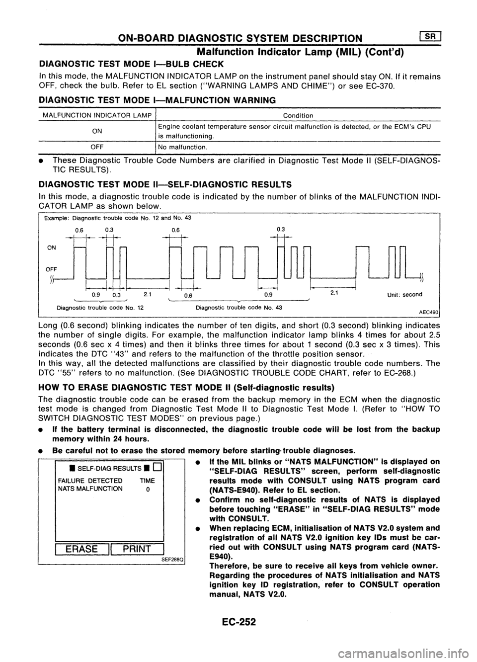
In this mode, adiagnostic troublecodeisindicated bythe number ofblinks ofthe MALFUNCTION INDI-
CATOR LAMPasshown below.
Example: Diagnostic troublecodeNo.12and No.43
0.6 0.3
ON
1111
OFF ~
0.9 0.3
0.6
--I~
2.1 0.6
0.9
0.3
Unit:second
Diagnostic troublecodeNo.12 Diagnostic
troublecodeNo.43
AEC490
• SELF-DIAG RESULTS.
0
FAILURE DETECTED TIME
NATS MALFUNCTION
0
I
ERASE
II
PRINT
I
SEF288Q
Long
(0.6second) blinkingindicates thenumber often digits, andshort (0.3second) blinkingindicates
the number ofsingle digits.Forexample, themalfunction indicatorlampblinks 4times forabout 2.5
seconds (0.6secx4times) andthen itblinks threetimes forabout 1second (0.3sec x3 times). This
indicates theDTC "43" andrefers tothe malfunction ofthe throttle position sensor.
In this way, allthe detected malfunctions areclassified bytheir diagnostic troublecodenumbers. The
DTC "55" refers tono malfunction. (SeeDIAGNOSTIC TROUBLECODECHART, refertoEC-268.)
HOW TOERASE DIAGNOSTIC TESTMODE II(Self-diagnostic results)
The diagnostic troublecodecanbeerased fromthebackup memory inthe ECM when thediagnostic
test mode ischanged fromDiagnostic TestMode IIto Diagnostic TestMode
I.
(Refer to"HOW TO
SWITCH DIAGNOSTIC TESTMODES" onprevious page.)
• Ifthe battery terminal isdisconnected, thediagnostic troublecodewillbelost from thebackup
memory within24hours.
• Becareful nottoerase thestored memory beforestarting- troublediagnoses.
• Ifthe MIL blinks or"NATS MALFUNCTION" isdisplayed on
"SELF-OIAG RESULTS"screen,perform self-diagnostic
results modewithCONSULT usingNATS program card
(NA TS-E940). RefertoEL section.
• Confirm noself-diagnostic resultsofNATS isdisplayed
before touching "ERASE" in"SELF-DiAG RESULTS"mode
with CONSULT.
• When replacing ECM,inltialisation ofNATS V2.0system and
registration ofall NATS V2.0 Ignition keyIDsmust becar-
ried outwith CONSULT usingNATS program card(NATS-
E940).
Therefore, besure toreceive allkeys from vehicle owner.
Regarding theprocedures ofNATS initialisation andNATS
ignition key
10
registration, refertoCONSULT operation
manual, NATS V2.0.
EC-252
Page 978 of 1701

ON-BOARDDIAGNOSTIC SYSTEMDESCRIPTION
CONSULT (Conl'd)
ACTIVE TESTMODE
TEST ITEM CONDITION JUDGEMENTCHECKITEM(REMEDY)
• Engine: Returntothe original
•Harness andconnector
FUEL INJECTION trouble
condition
Iftrouble symptom disappears,
•Fuel injectors
• Change theamount offuel
seeCHECK ITEM.
•Heated oxygen sensor
injection usingCONSULT .
• Engine: Afterwarming up,idle
IACV-AACIV the
engine.
Enginespeedchanges according •Harness andconnector
OPENING •
Change theIACV-AAC valve
tothe opening percent. •
IACV-AAC valve
opening percentusingCON-
SULT.
• Engine: Returntothe original
•Harness andconnector
ENG COOLANT trouble
condition
Iftrouble symptom disappears, •
Engine coolant temperature
• Change theengine coolant
.
TEMP see
CHECK ITEM. sensor
temperature indicationusing
•Fuel injectors
CONSULT .
• Engine: Returntothe original
trouble condition
Iftrouble symptom disappears,
IGNITION TIMING•Timing light:Set •
Adjust initialignition timing
• Retard theignition timingusingsee
CHECK ITEM.
CONSULT.
• Engine: Afterwarming up,idle •
Harness andconnector
the engine. •
Compression
POWER
•
AIC
switch "OFF"
Enginerunsrough ordies. •
Injectors
BALANCE •
Shift lever "N" •
Power transistor
• Cut offeach injector signalone •
Spark plugs
at atime using CONSULT . •
Ignition coils
• Ignition switch:ON
•Harness andconnector
COOLING FAN•
Turn thecooling fan"ON" andCooling
fanmoves andstops.
•Cooling fanmotor
"OFF" usingCONSULT .
• Ignition switch:ON(Engine
FUEL PUMP stopped)
Fuelpump relaymakes theoper- •
Harness andconnector
RELAY •
Turn thefuel pump relay"ON"
atingsound. •
Fuel pump relay
and "OFF" usingCONSULT
and listen tooperating sound.
EGRC •
Ignition switch:ON
• Turn solenoid valve"ON"and Solenoid
valvemakes anoperat- •
Harness andconnector
SOLENOID "OFF"withtheCONSULT andingsound. •
Solenoid valve
VALVE listentooperating sound.
SELF-LEARNING •
In this test, thecoefficient ofself-learning controlmixture ratioreturns tothe original coefficient by
CONT touching
"CLEAR" onthe screen.
EC-259
•
Page 996 of 1701
TROUBLEDIAGNOSIS -General Description
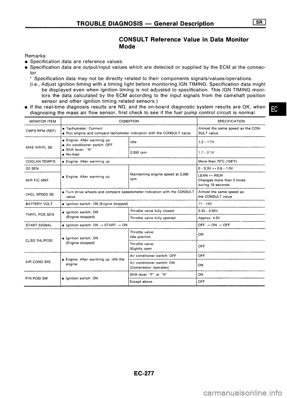
CONSULT Reference ValueinData Monitor
Mode
Remarks:
• Specification dataarereference values.
• Specification dataareoutput/input valueswhicharedetected orsupplied bythe ECM atthe connec-
tor.
*
Specification datamaynotbedirectly relatedtotheir components signals/values/operations.
(Le., Adjust ignition timingwithatiming lightbefore monitoring IGNTIMING. Specification datamight
be displayed evenwhen ignition timingisnot adjusted tospecification. ThisIGNTIMING moni-
tors thedata calculated bythe ECM according tothe input signals fromthecamshaft position
sensor andother ignition timingrelated sensors.)
• Ifthe real-time diagnosis resultsareNG, andtheon-board diagnostic systemresultsareOK, when •
diagnosing themass airflow sensor, firstcheck tosee ifthe fuel pump control circuitisnormal.
MONITOR ITEM CONDITION
SPECIFICATION
CMPS.RPM (REF)•
Tachometer: Connect Almostthesame speed asthe CON-
• Run engine andcompare tachometer indicationwiththeCONSULT value.SULTvalue.
• Engine: Afterwarming up
Idle 1.3-1.7V
MAS AIR/FL SE •
Air conditioner switch:OFF
• Shift lever: "N"
• No-load 2,000
rpm 1.7-2.1V
COOLAN TEMPIS •
Engine: Afterwarming up More
than70°C (15S0F)
02 SEN 0-
0.3V .....0.6 -1.0V
• Engine: Afterwarming up Maintaining
enginespeedat2,000
LEAN
+-->
RICH
MIR
FIC
MNT rpm
Changesmorethan5times
during 10seconds.
VHCL SPEED SE•
Turn drive wheels andcompare speedometer indicationwiththeCONSULT Almostthesame speed as
value the
CONSULT value
BATTERY VOLT •
Ignition switch:ON(Engine stopped) 11
-14V
• Ignition switch:ON Throttle
valvefullyclosed
0.35-0.65V
THRTL
pas
SEN
(Enginestopped)
Throttlevalvefullyopened Approx.4.0V
START SIGNAL •
Ignition switch:ON
->
START
->
ON OFF
->
ON
->
OFF
Throttle valve:
ON
• Ignition switch:ON Idle
position
CLSD THLIPOSI
(Enginestopped)
Throttlevalve:
Slightly open OFF
Air conditioner switch:OFF OFF
AIR COND SIG •
Engine: Afterwarming up,idle the
engine Air
conditioner switch:ON
ON
(Compressor operates)
Shift lever "P"or"N" ON
PIN POSI SW •
Ignition switch:ON
Exceptabove OFF
EC-277
Page 1098 of 1701
EF791AINJECTION
NOZZLE
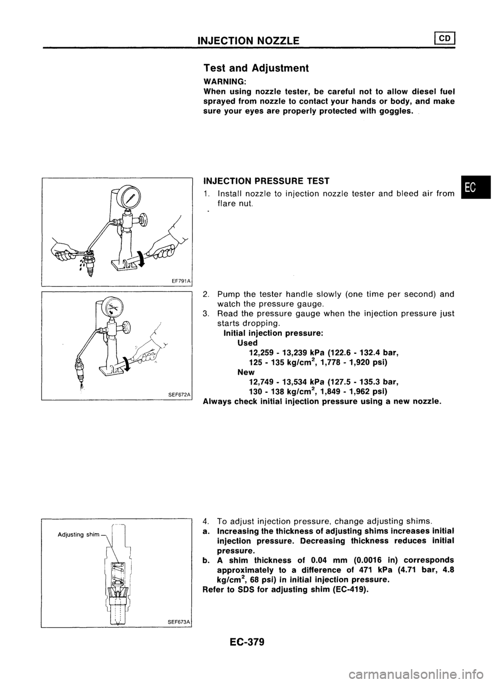
Test andAdjustment
WARNING:
When usingnozzle tester,becareful nottoallow diesel fuel
sprayed fromnozzle tocontact yourhands orbody, andmake
sure your eyes areproperly protected withgoggles .
INJECTION PRESSURE TEST
1. Install nozzle toinjection nozzletesterandbleed airfrom
flare nut.
•
SEF672A
2.
Pump thetester handle slowly(onetime persecond) and
watch thepressure gauge.
3. Read thepressure gaugewhentheinjection pressure just
starts dropping.
Initial injection pressure:
Used 12,259 -13,239 kPa(122.6 -132.4 bar,
125 -135 kg/cm
2,
1,778•1,920 psi)
New 12,749 -13,534 kPa(127.5 -135.3 bar,
130 -138 kg/cm
2,
1,849•1,962 psi)
Always checkinitialinjection pressure usinganew nozzle.
Adjusting shim
SEF673A
4.
Toadjust injection pressure, changeadjusting shims.
a. Increasing thethickness ofadjusting shimsincreases initial
injection pressure. Decreasing thicknessreducesinitial
pressure.
b. Ashim thickness of0.04 mm(0.0016 in)corresponds
approximately toadifference of471 kPa (4.71 bar,4.8
kg/cm
2,
68psi) ininitial injection pressure.
Refer toSDS foradjusting shim(EC-419).
EC-379
Page 1114 of 1701
TROUBLEDIAGNOSES
Quick-glow System(Cont'd)
@
CHECK COMPONENTS NG
(Glow relay, Glowplug,Engine coolant
temperature sensor,Key-inswitch, Igni-
tion switch).
Refer to"Component Inspection"(EC-
397).
OK
Disconnect andreconnect harnesscon-
nectors inthe circuit. Thenretest.
Trouble isnot fixed.
Check ECMpinterminals fordamage or
the connection ofECM harness connec-
tor. Reconnect ECMharness connector
and retest. Replace
malfunctioning
component(s).
•
BATIERY [
Voltage
OV
Ignition
key
START
[
ON
IN [
OUT
,
,
,
I
,
JL
SEC5558SYSTEM
OPERATION CHECK
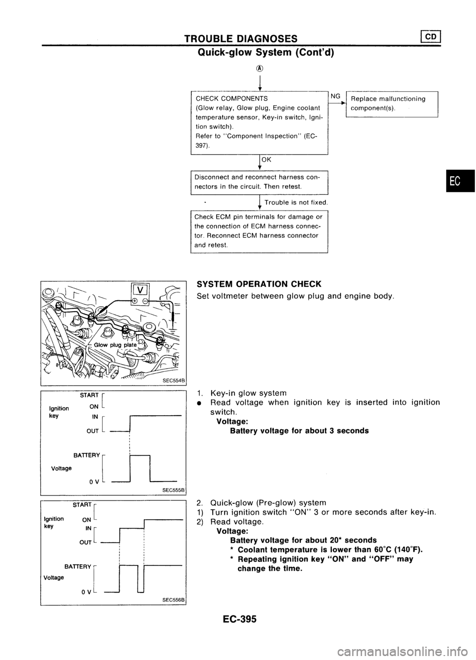
Set voltmeter betweenglowplugandengine body.
1. Key-in glowsystem
• Read voltage whenignition keyisinserted intoignition
switch.
Voltage: Battery voltage forabout 3seconds
Ignition
key
BATIERY [
Voltage
OV
SEC5568
2.
Quick-glow (Pre-glow)system
1) Turn ignition switch"ON"3or more seconds afterkey-in.
2) Read voltage.
Voltage: Battery voltage forabout 20*seconds
*
Coolant temperature islower than60°C(140°F).
* Repeating ignitionkey"ON" and"OFF" may
change thetime.
EC-395
Page 1118 of 1701
SYSTEMDESCRIPTION TROUBLE
DIAGNOSES
Partial LoadAdvance (PLA)Control
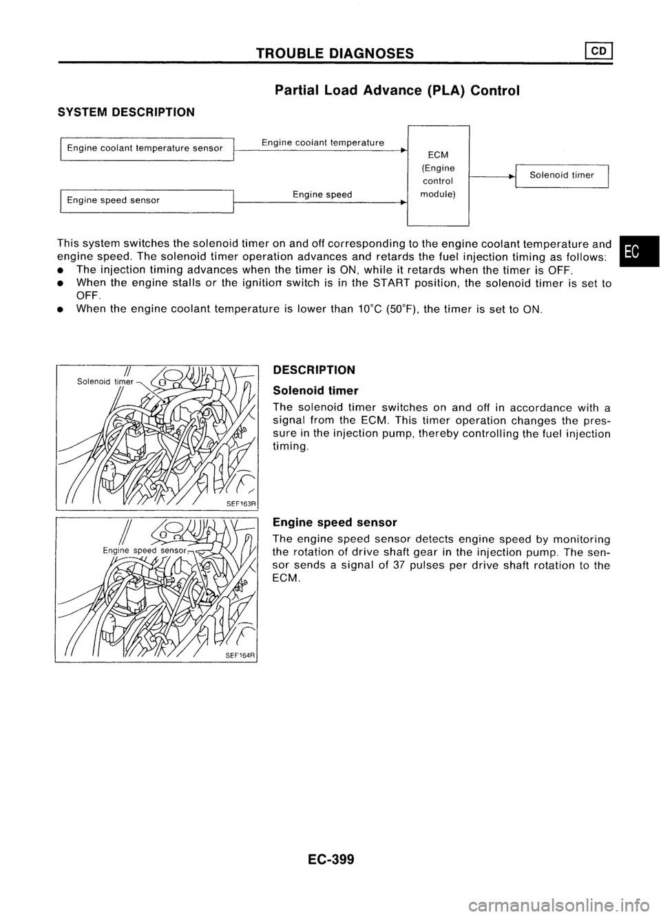
This system switches thesolenoid timeronand offcorresponding tothe engine coolant temperature and
engine speed.Thesolenoid timeroperation advancesandretards thefuel injection timingasfollows:
• The injection timingadvances whenthetimer isON, while itretards whenthetimer isOFF.
• When theengine stallsorthe ignition switchisin the START position, thesolenoid timerisset to
OFF.
• When theengine coolant temperature islower than10°C(50°F), thetimer isset toON.
Engine
coolant temperature sensor
Engine speedsensor Engine
coolant temperature
Engine speed
ECM
(Engine control
module) Solenoid
timer
•
DESCRIPTION
Solenoid timer
The solenoid timerswitches onand offinaccordance witha
signal fromtheECM. Thistimer operation changesthepres-
sure inthe injection pump,thereby controlling thefuel injection
timing.
Engine speedsensor
The engine speedsensor detects enginespeedbymonitoring
the rotation ofdrive shaftgearinthe injection pump.Thesen-
sor sends asignal of37 pulses perdrive shaftrotation tothe
ECM.
EC-399
Page 1377 of 1701
•SHORT CIRCUIT
• SHORT TOGROUND
HOW
TOPERFORM EFFICIENT DIAGNOSIS FORANELECTRICAL INCIDENT
Circuit Inspection
•
A circuit isopen when thereisno continuity throughasection ofthe circuit.
There aretwo types ofshorts.
Whenacircuit contacts anothercircuitandcauses the
normal resistance tochange.
When acircuit contacts aground sourceandgrounds the
circuit.
INTRODUCTION
In general, testingelectrical circuitsisan easy taskifitis approached inalogical andorganized method.
Before beginning itis important tohave allavailable information onthe system tobe tested. Also,get
a thorough understanding ofsystem operation. Thenyouwillbeable touse theappropriate equipment
and follow thecorrect testprocedure.
You may have tosimulate vehiclevibrations whiletesting electrical components.
Gentlyshake
thewir-
ing harness orelectrical component todo this.
OPEN
SHORT
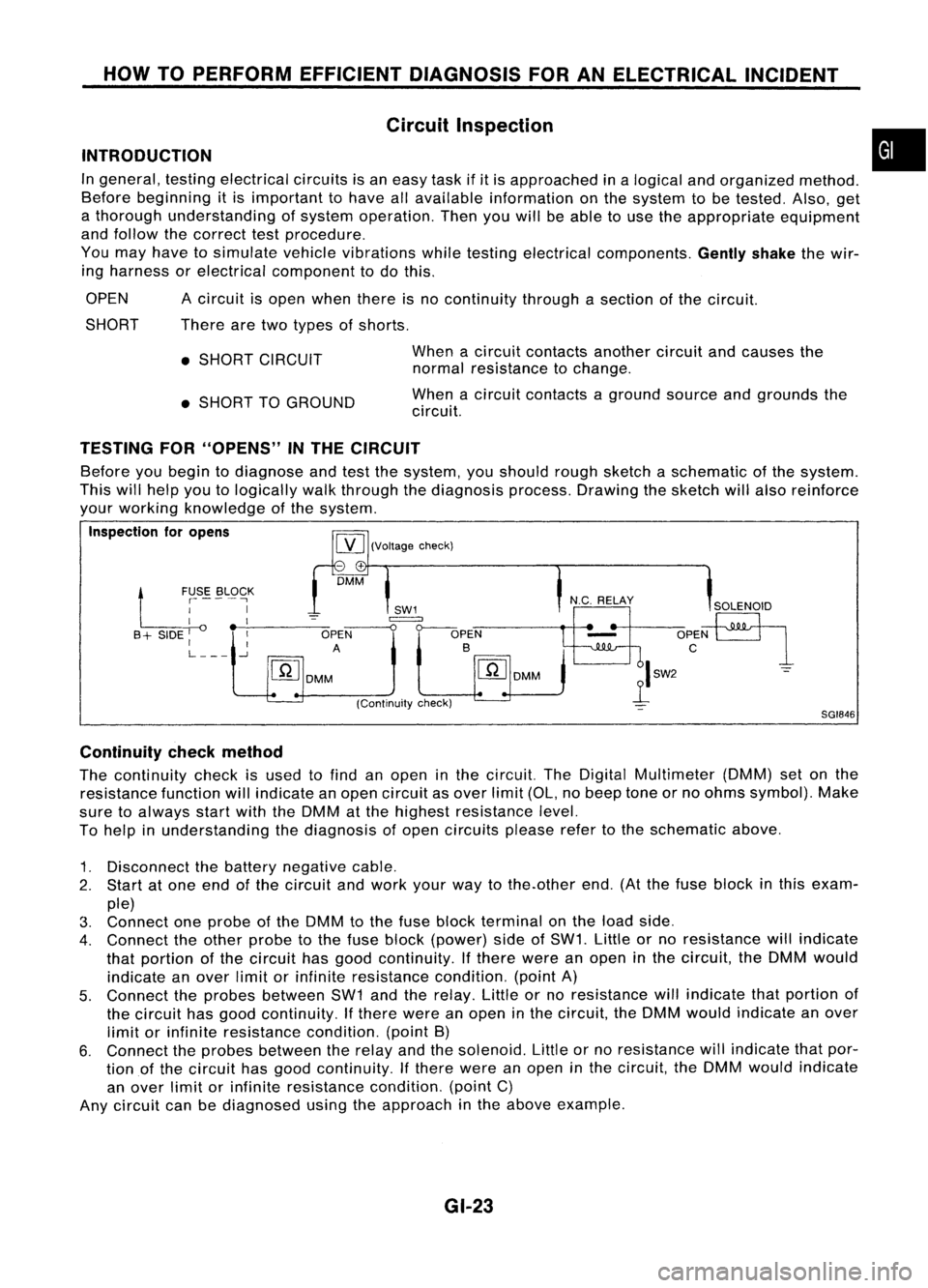
TESTING FOR"OPENS" INTHE CIRCUIT
[YJ
(Voltage check)
Before
youbegin todiagnose andtestthesystem, youshould roughsketch aschematic ofthe system.
This willhelp youtologically walkthrough thediagnosis process.Drawingthesketch willalso reinforce
your working knowledge ofthe system.
Inspection foropens
-+
DMM
Ll
~SE. ~L9~K
I
I
I __-,----
B + SIDE
I
OPEN
I I
A
L
-.J
[ill
DMM
SGI846
Continuity checkmethod
The continuity checkisused tofind anopen inthe circuit. TheDigital Multimeter (DMM)setonthe
resistance functionwillindicate anopen circuit asover limit(OL,nobeep toneorno ohms symbol). Make
sure toalways startwiththeDMM atthe highest resistance level.
To help inunderstanding thediagnosis ofopen circuits pleaserefertothe schematic above.
1. Disconnect thebattery negative cable.
2. Start atone end ofthe circuit andwork yourwaytothe.other end.(Atthe fuse block inthis exam-
ple)
3. Connect oneprobe ofthe DMM tothe fuse block terminal onthe load side.
4. Connect theother probe tothe fuse block (power) sideofSW1. Littleorno resistance willindicate
that portion ofthe circuit hasgood continuity. Ifthere wereanopen inthe circuit, theDMM would
indicate anover limitorinfinite resistance condition.(pointA)
5. Connect theprobes between SW1andtherelay. Littleorno resistance willindicate thatportion of
the circuit hasgood continuity. Ifthere wereanopen inthe circuit, theDMM would indicate anover
limit orinfinite resistance condition.(pointB)
6. Connect theprobes between therelay andthesolenoid. Littleorno resistance willindicate thatpor-
tion ofthe circuit hasgood continuity. Ifthere wereanopen inthe circuit, theDMM would indicate
an over limitorinfinite resistance condition.(pointC)
Any circuit canbediagnosed usingtheapproach inthe above example.
GI-23