Page 1371 of 1701
HOWTOREAD WIRING DIAGRAMS
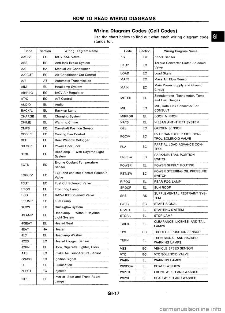
Wiring Diagram Codes(CellCodes)
Use thechart below to'find outwhat each wiring diagram code•
stands for,
Code Section WiringDiagram Name
AACIV ECIACV-AAC
Valve
ABS BR
Anti-lock BrakeSystem
A/C HAManualAirConditioner
A/CCUT ECAir
Conditioner CutControl
A/T ATAutomatic Transmission
AIM ELHeadlamp System
AIRREG ECIACV-Air Regulator
AT/C ECA/TControl
AUDIO ELAudio
BACK/L ELBack-up Lamp
CHARGE ELCharging System
CHIME ELWarning Chime
CMPS EC
Camshaft PositionSensor
COOllF ECCooling
FanControl
DEF ELRearWindow Defogger
D/LOCK ELPowerDoorLock
DTRL ELHeadlamp
-With Daytime Light
System
ECTS ECEngine
Coolant Temperature
Sensor
EGR andcanister ControlSolenoid
EGRCIV EC
Valve
FCUT ECFuel
CutSolenoid Valve
F/FOG ELFront
FogLamp
FICO ECIACV-FICD
SolenoidValve
F/PUMP ECFuel
Pump
GLOW ECQuick-glow
system
H/LAMP ELHeadlamp
-Without Daytime
Light System
H/SEAT ELHeated
Seat
HEAT HA
Heater
HLC ELHeadlamp
Washer
H02S ECHeated
Oxygen Sensor
HORN ELHorn,
Cigarette Lighter,Clock
IATS ECIntake
AirTemperature Sensor
IGN/SG ECIgnition
Signal
ILL ELIllumination
INJECT ECInjector
INT/L ELInterior,
SpotandTrunk Room
Lamps Code
Section WiringDiagram Name
KS ECKnock
Sensor
LKUP ECTorque
Converter ClutchSolenoid
Valve
LOAD ECLoadSignal
MAFS ECMass
AirFlow Sensor
MAIN ECMain
Power Supply andGround
Circuit
METER ELSpeedometer,
Tachometer,Temp.
and Fuel Gauges
MIL ECMIL,
Data LinkConnector For
CONSULT
MIRROR ELDOOR
MIRROR
NATS ELNISSAN
ANTI-THEFT SYSTEM
02S ECOXYGEN
SENSOR
EC EVAP
CANISTER PURGECON-
PGCIV TROLSOLENOID VALVE
PLA ECPARTIAL
LOADADVANCE CON-
TROL
EC PARK/NEUTRAL
POSITION
PNP/SW SWITCH
POWER ELPOWER
SUPPLY ROUTING
POWER STEERING OILPRESSURE
PST/SW EC
SWITCH
R/FOG ELREAR
FOGLAMP
SROOF ELSUN
ROOF
SUPPLEMENTAL RESTRAINTSYS-
SRS RS
TEM
S/SIG ECST
ART SIGNAL
START ELSTARTING
SYSTEM
STOP/L ELSTOP
LAMP
TAllIL ELCLEARANCE,
LICENSE,ANDTAIL
LAMPS
TPS ECTHROTTLE
POSITIONSENSOR
TURN SIGNAL ANDHAZARD
TURN EL
WARNING LAMPS
VSS ECVEHICLE
SPEEDSENSOR
VTC ECVTC
SOLENOID VALVE
WARN ELWARNING
LAMPS
WINDOW ELPOWER
WINDOW
WIPER ELFRONT
WIPERANDWASHER
WIP/R ELREAR
WIPER ANDWASHER
GI-17
Page 1380 of 1701
HOWTOPERFORM EFFICIENT DIAGNOSIS FORANELECTRICAL INCIDENT
Circuit Inspection (Cont'd)
VOLTAGE DROPTESTS
Voltage droptests areoften usedtofind components orcircuits whichhaveexcessive resistance. A
voltage dropinacircuit iscaused byaresistance
whenthecircuit isin operation.
Check thewire inthe illustration. Whenmeasuring resistancewithohmmeter, contactbyasingle strand
of wire willgive reading of0ohms. Thiswould indicate agood circuit. Whenthecircuit operates, this
single strand ofwire isnot able tocarry thecurrent. Thesingle strand willhave ahigh resistance tothe
current. Thiswillbepicked upasaslight voltage drop.
Unwanted resistance canbecaused bymany situations asfollows:
Undersized wiring(single strandexample)
Corrosion onswitch contacts
Loose wireconnections orsplices.
If
repairs areneeded alwaysusewire thatisof the same orlarger gauge.
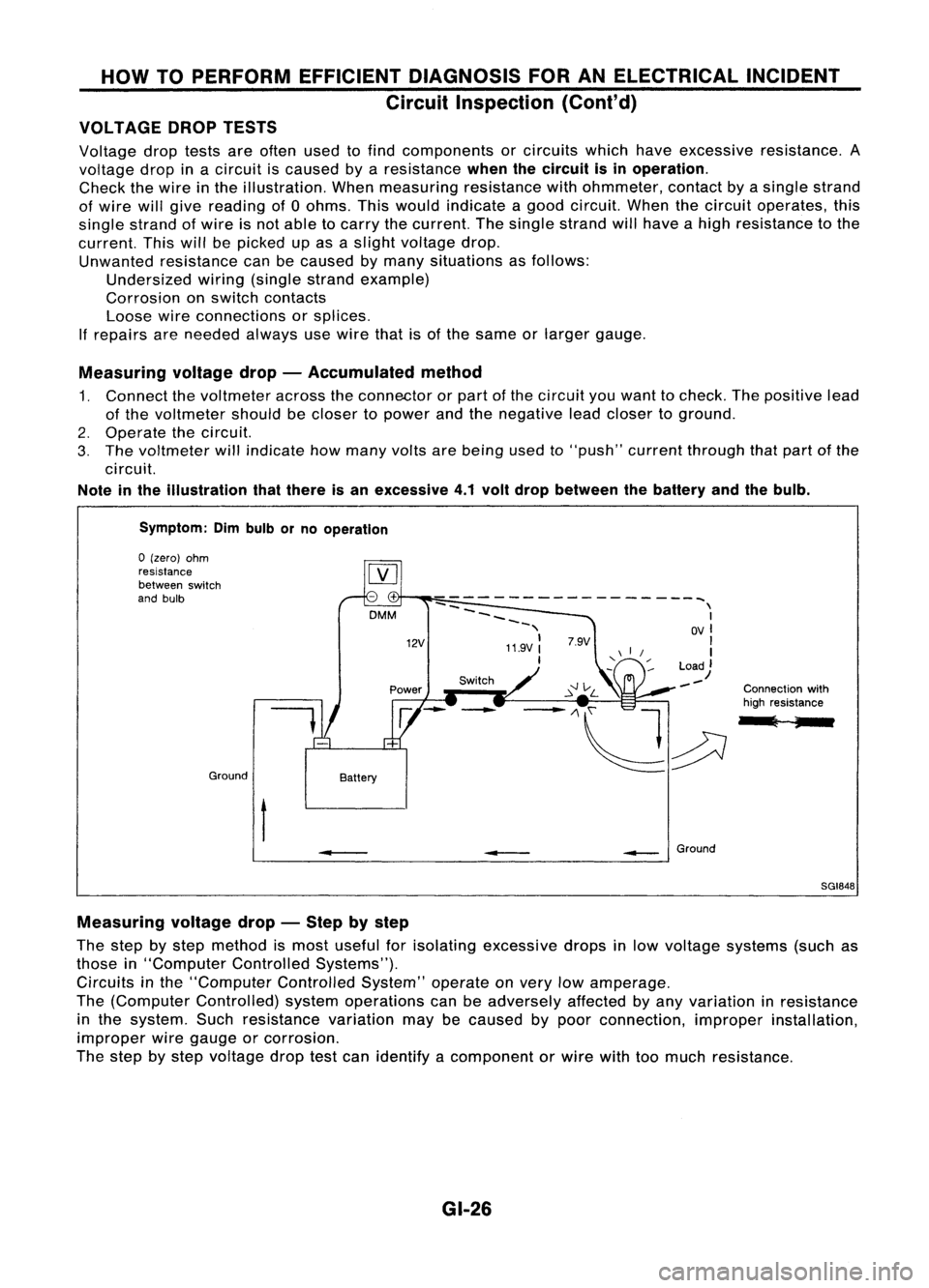
Measuring voltagedrop-Accumulated method
1. Connect thevoltmeter acrosstheconnector orpart ofthe circuit youwant tocheck. Thepositive lead
of the voltmeter shouldbecloser topower andthenegative leadcloser toground.
2. Operate thecircuit.
3. The voltmeter willindicate howmany voltsarebeing usedto"push" current through thatpart ofthe
circuit.
Note inthe illustration thatthere isan excessive 4.1volt drop between thebattery andthebulb.
Symptom: Dimbulb orno operation
Switch Connectionwith
high resistance
l ;
--
------------------~
--
\
~~~~ I
-, OVI
11.9V:
'I
I
Load)
--
12V
DMM
Battery
Ground
o
(zero) ohm
resistance
between switch
and bulb
t
•
__
Ground
SGI848
Measuring voltagedrop-Step bystep
The step bystep method ismost useful forisolating excessive dropsinlow voltage systems (suchas
those in"Computer ControlledSystems").
Circuits inthe "Computer ControlledSystem"operateonvery lowamperage.
The (Computer Controlled) systemoperations canbeadversely affectedbyany variation inresistance
in the system. Suchresistance variationmaybecaused bypoor connection, improperinstallation,
improper wiregauge orcorrosion.
The step bystep voltage droptestcan identify acomponent orwire withtoomuch resistance.
GI-26
Page 1403 of 1701
HEATER
&
AIR CONDITIONER
SECTION
HA
CONTENTS
When youread wiring diagrams:
• Read GIsection, "HOWTOREAD WIRING DIAGRAMS" .
• See ELsection, "POWER SUPPLYROUTING" forpower distribution circuit.
When youperform troublediagnoses, readGIsection, "HOWTOFOLLOW FLOWCHART
IN TROUBLE DIAGNOSES" and"HOW TOPERFORM EFFICIENT DIAGNOSIS FORAN
ELECTRICAL INCIDENT".
PRECAUTIONS
ANDPREPARATION 2
Supplemental RestraintSystem(SRS)"AIR
BAG" (DualAirBag System) 2
Supplemental RestraintSystem(SRS)"AIR
BAG", (Single AirBag System) 2
Precautions forWorking withHFC-134a (R-
134a) 3
General Refrigerant Precautions 3
Precautions forRefrigerant Connection 4
Precautions forServici ngCompressor. ..5
Special Service Tools 5
HFC-134a (R-134a)ServiceToolsand
Equipment. 6
Precautions forService Equipment 8
DESCRIPTION 10
Refrigeration Cycle .10
Component Layout 11
Discharge AirFlow 12
Control Operation 13
TROUBLE DIAGNOSES 14
Contents 14Wiring
Diagram -HEATER - 36
Wiring Diagram -
AIC - 38
SERVICE PROCEDURES 66
HFC-134a (R-134a)ServiceProcedure 66
Maintenance ofLubricant Quantityin
Compressor 68
Refrigerant Lines 70
Compressor Mounting 75
Belt Tension 76
Fast IdleControl Device(FICO) 76
Compressor -Model DKV-11D andDKV-14D
(ZEXEL make) 77
Compressor Clutch 77
Thermal Protector 80
Compressor -Model CR-14 (Calsonic make)80
Compressor Clutch ..80
Thermal Protector 82
Ventilation AirFilter 83
SERVICE DATAANDSPECIFICATIONS (SDS)84
General Specifications 84
Inspection andAdjustment 84
•
Page 1416 of 1701
TROUBLEDIAGNOSES
Contents
How toPerform TroubleDiagnoses forQuick andAccurate Repair HA-15
Operational Check HA-16
Symptom Chart HA-18
Preliminary Check HA-20
PRELIMINARY CHECK1
(A/C
does notblow coldair.) HA-20
PRELIMINARY CHECK2
(Air outlet doesnotchange.) HA-21
PRELIMINARY CHECK3
(Noise) HA-22
PRELIMINARY CHECK4
(I nsufficient heating) HA-23
Performance TestDiagnoses HA-24
INSUFFICIENT COOLING HA-24
Performance Chart HA-26
TEST CONDITION HA-26
TEST READING HA-26
Trouble Diagnoses forAbnormal Pressure HA-27
Harness Layout. HA-31
Circuit Diagram -Air Conditioner HA-34
Wiring Diagram -HEATER - HA-36
Wiring Diagram -AIC - HA-38
Main Power Supply andGround CircuitCheck HA-49
Diagnostic Procedure1
(SYMPTOM: Blowermotordoesnotrotate.) HA-50
Diagnostic Procedure2
(SYMPTOM: Intake doordoes notchange.) HA-52
Diagnostic Procedure3
(SYMPTOM: Magnetclutchdoesnotoperate when
A/C
switch andfanswitch areON.)
- For GAand SRengines HA-54
- For CDengine HA-59
Electrical Components Inspection HA-62
Control Linkage Adjustment HA-64
System Description HA-65
HA-14
Page 1621 of 1701
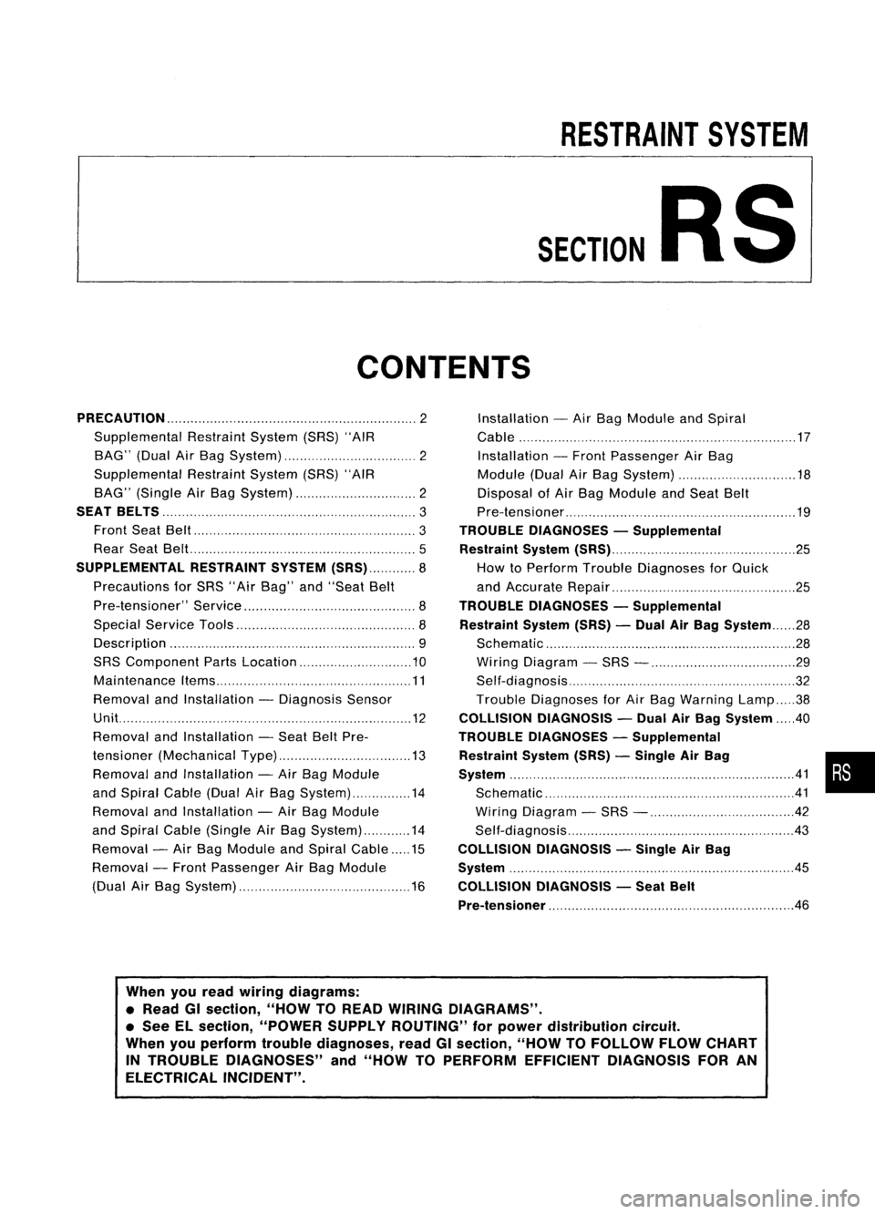
RESTRAINTSYSTEM
SECTION
RS
CONTENTS
PRECAUTION 2
Supplemental RestraintSystem(SRS)"AIR
BAG" (DualAirBag System) 2
Supplemental RestraintSystem(SRS)"AIR
BAG" (Single AirBag System) 2
SEAT BELTS
3
Front SeatBelt 3
Rear SeatBel!. 5
SUPPLEMENTAL RESTRAINTSYSTEM(SRS) 8
Precautions forSRS "AirBag" and"Seat Belt
Pre-tensioner" Service 8
Special Service Tools 8
Description 9
SRS Component PartsLocation 10
Maintenance Items 11
Removal andInstallation -Diagnosis Sensor
Unit. 12
Removal andInstallation -Seat BeltPre-
tensioner (Mechanical Type) 13
Removal andInstallation -Air Bag Module
and Spiral Cable(DualAirBag System) 14
Removal andInstallation -Air Bag Module
and Spiral Cable(Single AirBag System) 14
Removal -Air Bag Module andSpiral Cable 15
Removal -Front Passenger AirBag Module
(Dual AirBag System) 16Installation
-Air Bag Module andSpiral
Cable 17
Installation -Front Passenger AirBag
Module (DualAirBag System) 18
Disposal ofAir Bag Module andSeat Belt
Pre-tensioner 19
TROUBLE DIAGNOSES -Supplemental
Restraint System(SRS) 25
How toPerform TroubleDiagnoses forQuick
and Accurate Repair 25
TROUBLE DIAGNOSES -Supplemental
Restraint System(SRS)-Dual AirBag System 28
Schematic 28
Wiring Diagram -SRS - 29
Self-diagnosis 32
Trouble Diagnoses forAir Bag Warning Lamp38
COLLISION DIAGNOSIS -Dual AirBag System .40
TROUBLE DIAGNOSES -Supplemental
Restraint System(SRS)-Single AirBag •
System 41•
Schematic 41
Wiring Diagram -SRS - 42
Self-diagnosis 43
COLLISION DIAGNOSIS -Single AirBag
System .45
COLLISION DIAGNOSIS -Seat Belt
Pre-tensioner
.46
When youread wiring diagrams:
• Read GIsection, "HOWTOREAD WIRING DIAGRAMS" .
• See ELsection, "POWER SUPPLYROUTING" forpower distribution circuit.
When youperform troublediagnoses, readGIsection, "HOWTOFOLLOW FLOWCHART
IN TROUBLE DIAGNOSES" and"HOW TOPERFORM EFFICIENT DIAGNOSIS FORAN
ELECTRICAL INCIDENT".
Page:
< prev 1-8 9-16 17-24