Page 1297 of 1701
OILPAN
Scraper '""'\
SEM3508Removal
1. Drain oil.
2. Remove oilpan using toolasillustrated.
1) Insert Toolbetween oilpan andcylinder block.
• Do not drive sealcutter intooilpump orrear oilseal
retainer portion,oraluminum matingsurfaces willbedam-
aged.
• Do not insert screwdriver, oroil pan flange willbe
deformed.
2) Slide Toolbytapping itwith ahammer, andremove oilpan.
Installation
1. Before installing oilpan, remove alltraces ofliquid gasket
from mating surface usingascraper.
• Also remove tracesofliquid gasket frommating surface of
cylinder block.
• Besure liquid gasket is3.5 to4.5 mm (0.138 to0.177 in)
wide.
Use Genuine LiquidGasket orequivalent.
Cut here.
~--=J
Liquidgasket
SLC906
7
mm
(0.28 In)
-1
Inner
side
2.
Apply liquidgasket toinner sealing surface asshown atleft.
Groove Bolthole
SEM9098
EM-118
Page 1320 of 1701

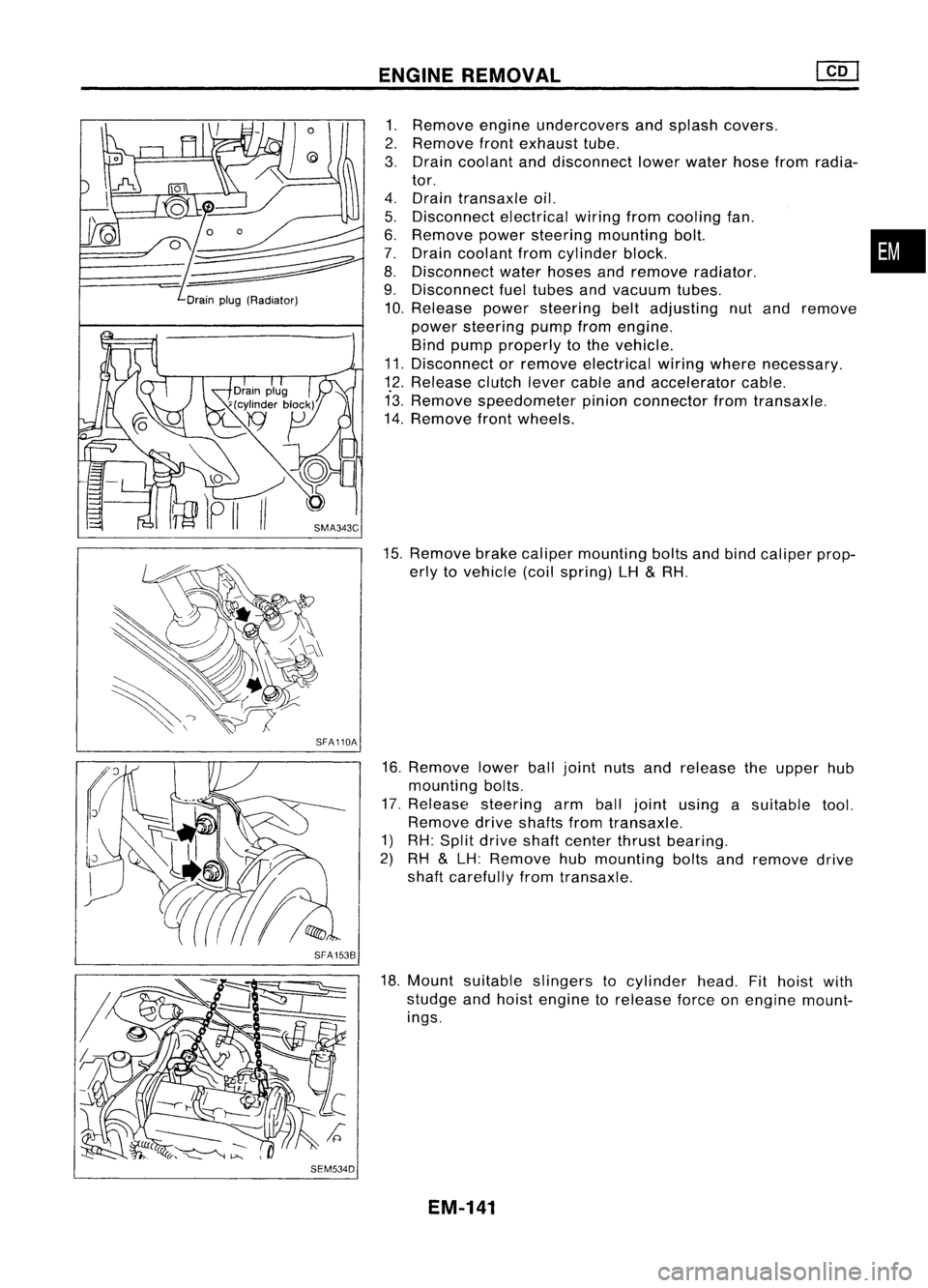
Drainplug(Radiator)
SFA110A
SFA 1538
SEM534D ENGINE
REMOVAL
1. Remove engineundercovers andsplash covers.
2. Remove frontexhaust tube.
3. Drain coolant anddisconnect lowerwater hosefromradia-
tor.
4. Drain transaxle oil.
5. Disconnect electricalwiringfromcooling fan.
6. Remove powersteering mounting bolt. •
7. Drain coolant fromcylinder block.
8. Disconnect waterhoses andremove radiator.
9. Disconnect fueltubes andvacuum tubes.
10. Release powersteering beltadjusting nutand remove
power steering pumpfromengine.
Bind pump properly tothe vehicle.
11. Disconnect orremove electrical wiringwhere necessary.
12. Release clutchlevercable andaccelerator cable.
13. Remove speedometer pinionconnector fromtransaxle.
14. Remove frontwheels.
15. Remove brakecaliper mounting boltsandbind caliper prop-
erly tovehicle (coilspring) LH
&
RH.
16. Remove lowerballjoint nutsandrelease theupper hub
mounting bolts.
17. Release steering armballjoint using asuitable tool.
Remove driveshafts fromtransaxle.
1) RH: Split drive shaftcenter thrustbearing.
2) RH
&
LH: Remove hubmounting boltsandremove drive
shaft carefully fromtransaxle.
18. Mount suitable slingers tocylinder head.Fithoist with
studge andhoist engine torelease forceonengine mount-
ings.
EM-141
Page 1541 of 1701

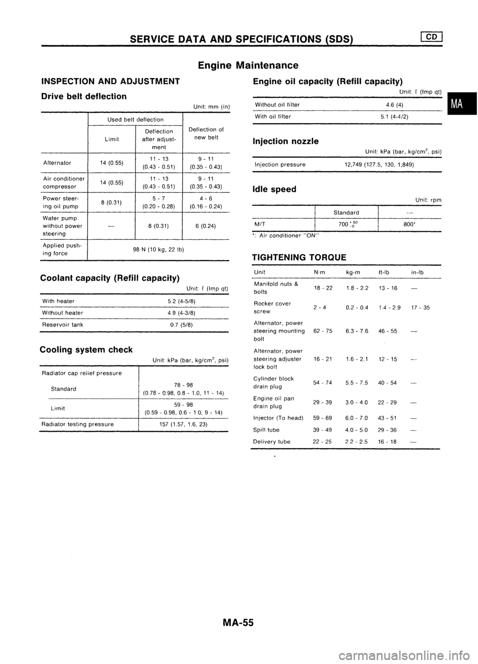
SERVICEDATAANDSPECIFICATIONS (50S)
Used beltdeflection
Deflection Deflection
of
Limit afteradjust- new
belt
ment
Alternator 14(055) 11
-13 9-11
(0.43 -0.51)
(0.35-0.43)
Air conditioner
14(0.55) 11
-13
9-11
compressor (0.43
-0.51)
(0.35-0.43)
Power steer-
8(0.31) 5
-7
4-6
ing oilpump (0.20-0.28)
(0.16-0.24)
Water pump
without power
-
8
(0.31) 6(0.24)
steering
Applied push-
98N(10 kg, 22Ib)
ing force
Coolant capacity (Refillcapacity)
INSPECTION
ANDADJUSTMENT
Drive beltdeflection
Unit:kPa(bar, kg/cm', psi)
12,749 (127.5, 130,1,849)
Without
oilfilter
With oilfilter
Injection pressure
Injection
nozzle
Idle speed
Unit:rpm
Standard
M/T
700
'go
800'
': Air conditioner "ON"
TIGHTENING TORQUE
Unit N'mkg-m
ft-Ib in-Ib
Manifold nuts
&
18-22
1.8-2.2
bolts 13
-16
Rocker cover
2-4
0.2-0.4 1.4-2.9 17-35
screw
Alternator, power
steering mounting 62-75
6.3-76 46
-55
bolt
Alternator, power
steering adjuster 16
-21
1.6-2.1
12-15
lock bolt
Cylinder block
54-74
5.5-7.5 40
-54
drain plug
Engine oilpan
29-39 3.0-4.0 22-29
drain plug
Injector (Tohead)
59-69 6.0-7.0 43-51
Spill tube 39-49
4.0-5.0 29-36
Delivery tube 22-25 2.2-2.5
16-18
Engine
Maintenance
Engine oilcapacity (Refillcapacity)
Unit:[(Imp qt)•
46 (4)
51 (4--1/2)
Unit:
mm(in)
Unit:
f
(Imp qt)
5.2 (4-5/8)
49 (4-3/8)
0.7 (5/8)
Unit: kPa(bar, kg/cm', psi)
78 -98
(0.78 -0.98, 08-1.0, 11-14)
59 -98
(0.59 -0.98, 06-10, 9-14)
157 (1.57, 1.6,23)
Standard
Limit
With
heater
Without heater
Reservoir tank
Radiator caprelief pressure
Radiator testingpressure
Cooling
systemcheck
MA-55
Page 1549 of 1701
REMOVALANDINSTALLATION
Removal
1. Remove batterynegative terminal.
2. Remove airduct.
3. Disconnect clutchcontrol cable.(Except forCD20 engine
models)
Remove clutchoperating cylinderandclutch operating cyl-
inder bracket fromtransaxle. (CD20engine models)
4. Disconnect back-uplampswitch, neutralposition switch,
speedometer sensorandground harness connectors.
5. Remove startermotorfromtransaxle.
6. Remove shiftcontrol rodand support rodfrom transaxle.
7. Drain gearoilfrom transaxle.
8. Remove driveshafts. RefertoFA section ("Removal",
"FRONT AXLE-Drive Shaft").
9. Jack uptransaxle togetherwithengine slightly andinsert
wooden blockbetween centermember andengine oilpan.
CAUTION:
Do not place jackunder oilpan drain plug.
10. Remove rearandLHmounts supporting transaxlewithjack.
11. Remove boltssecuring transaxle.
12. Lower transaxle.
MT-7
•
Page 1552 of 1701
SEC.320 MAJOR
OVERHAUL
Case Components
I
RS5F30A
&
RS5F31 A
I
.. -- RS5F31A---
~16 -21
(1.6 -2.1, 12. 15)
@ ~Mating
surface to
transmiSSion
case ----
@
~20 -29 (2.0 -3.0, 14-22)-
~ Thread ofbolt
(1)
Clutch housing
@)
O-ring
@
Input shaftoilseal
@
Case cover
@
Oilpocket
@
Back-up lampswitch
@
Bearing retainer
@
Differential oilseal
@
Bearing retainer
@
Drain plug
@
Torx screw
@l
Transmission case
(J)
Filler plug
@
Oilgutter
@
Airbreather
@
Reverse idlershaft
@
Welch plug
@
Oilchannel
MT-10
@
~
15-20 (1.5 -2.0, 11-14)
~ Thread ofbolt
Ij] :
Nom (kg-m, in-Ib)
tr'J :
Nom (kg-m, ft-Ib)
~ :Apply recommended sealant
(Nissan genuine part:KP610-00250) orequivalent.
*: :
Pay attention toits direction.
SMT755C
@
Striking rodoilseal
@J
Boot
@
Neutral position switch(GA
engine) orswitch plug(CD
engine)
@
Differential oilseal
@
O-ring
@
Speedometer pinionassembly
Page 1575 of 1701

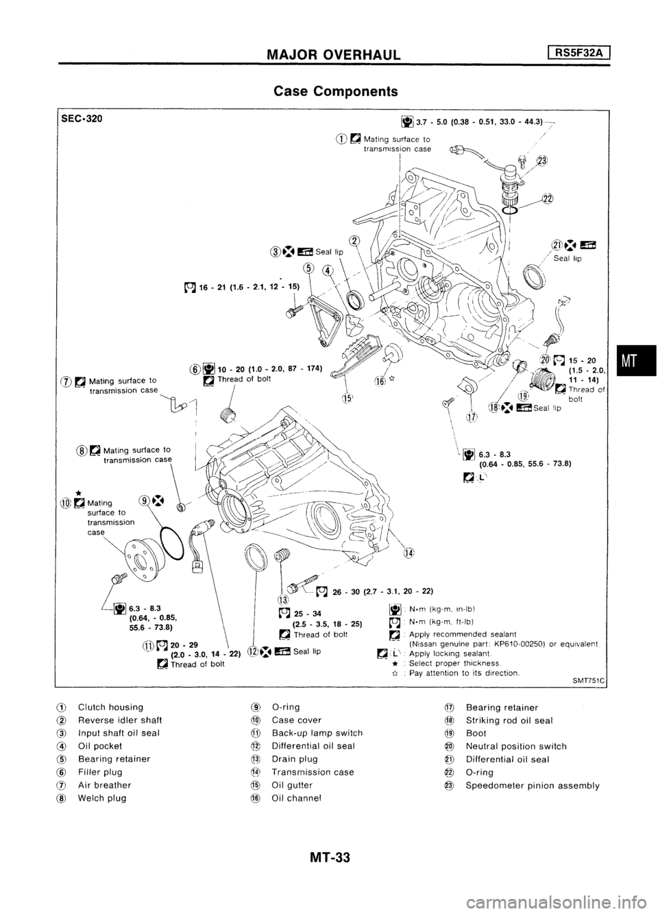
MAJOROVERHAUL
I
RS5F32A
I
Case Components
•
\
\L~
6.3.8.3
(0.64 -0.85, 55.6-73.8)
~.L'
J
(15,'
~
3.7•5.0 (0.38 •0.51, 33.0-44.3)
CD ~
Mating surface to
transmission case~
I
;1
~3J
1J2»~
o//~
d~~~
!-~~
i~=1D.
(]?
CID.:.
m
Seal lip \
\
.
~)~
//\
1~
~'
(fl)
to.J
20-29 \
- (2.0-3.0, 14-22)
~ Thread ofbolt
@
~
Mating surface to
SEC.320
@~
10.20 (1.0-2.0, 87-174)
W ~
Mating surface to ~Thread ofbolt
"""mi"ioo '""
\1:.0
1 ~ /',
. WO,,~., .,.~
~~~> '\
t,,~~~~
o
I:::t:\ ~___-- __~
j)\~
~i)~/
(ro\~\~)
. ------ ~~,/ ~Q~
I
f""\
~~~ ..~ Q{
t~A
26-30 (2.7 -3.1, 20-22)
!13i
~ 25_34 ~N.m(kg-m, In-Ib\
(2.5 -3.5, 18-25)
A
N.m(kg-m, ft-Ib)
~ Thread ofbolt ~.Apply recommended sealant
(Nissan genuine part:KP610-00250) orequivalent
12)~.
m
Seal lip ~
,.1..',
Apply locking sealant
* :
Select proper thickness.
-tI .
Pay attention toits direction,
*
@~Mating
SMT751C
G)
Clutch housing
@
Reverse idlershaft
@
Input shaftoilseal
@
Oilpocket
@
Bearing retainer
@
Filler plug
(J)
Airbreather
@
Welch plug
(9)
O-ring
@
Case cover
CfD
Back-up lampswitch
@
Differential oilseal
@
Drain plug
@
Transmission case
@
Oilgutter
@
Oilchannel
@
Bearing retainer
@l
Striking rodoilseal
QID
Boot
@
Neutral position switch
@
Differential oilseal
@
O-ring
@
Speedometer pinionassembly
MT-33
Page 1617 of 1701

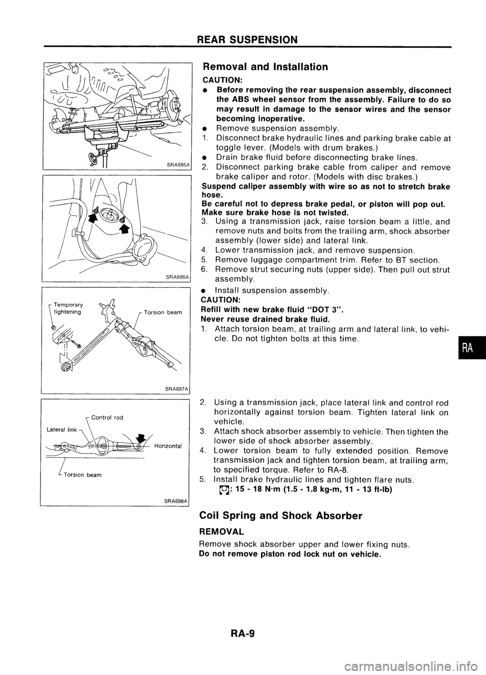
SRA696A
SRA697A
S
Control rod
Lateral link
~H";""I"
ITorsion
beam
SRA698AREAR
SUSPENSION
Removal andInstallation
CAUTION:
• Before removing therear suspension assembly,disconnect
the ABS wheel sensor fromtheassembly. Failuretodo so
may result indamage tothe sensor wiresandthesensor
becoming inoperative.
• Remove suspension assembly.
1. Disconnect brakehydraulic linesandparking brakecableat
toggle lever.(Models withdrum brakes.)
• Drain brake fluidbefore disconnecting brakelines.
2. Disconnect parkingbrakecablefromcaliper andremove
brake caliper androtor. (Models withdiscbrakes.)
Suspend caliperassembly withwire soasnot tostretch brake
hose.
Be careful nottodepress brakepedal, orpiston willpop out.
Make surebrake hoseisnot twisted.
3. Using atransmission jack,raise torsion beamalittle, and
remove nutsandbolts fromthetrailing arm,shock absorber
assembly (lowerside)andlateral link.
4. Lower transmission jack,andremove suspension.
5. Remove luggagecompartment trim.Refer toBT section.
6. Remove strutsecuring nuts(upper side).Thenpulloutstrut
assembly.
• Install suspension assembly.
CAUTION: Refill withnewbrake fluid"DOT
3".
Never reusedrained brakefluid.
1. Attach torsion beam,attrailing armandlateral link,tovehi-
cle. Donot tighten boltsatthis time.
2. Using atransmission jack,place lateral linkand control rod
horizontally againsttorsionbeam.Tighten laterallinkon
vehicle.
3. Attach shockabsorber assembly tovehicle. Thentighten the
lower sideofshock absorber assembly.
4. Lower torsion beamtofully extended position.Remove
transmission jackandtighten torsion beam,attrailing arm,
to specified torque.RefertoRA-8.
5. Install brakehydraulic linesandtighten flarenuts.
~: 15-18 N'm (1.5.1.8 kg-m,11-13 ft-Ib)
Coil Spring andShock Absorber
REMOVAL
Remove shockabsorber upperandlower fixing nuts.
Do not remove pistonrodlock nutonvehicle.
RA-9
•
Page:
< prev 1-8 9-16 17-24