Page 991 of 1701
![NISSAN ALMERA N15 1995 Service Manual
I!]
CHECK IDLEADJ. SCREW INITIALSET
NG
Adjust engine speedby
---..
RPM.
turningidleadjusting
00
1.
Select "IGNTIMING ADJ"in screw.
"WORK SUPPORT" mode.
2. When touching "STAR NISSAN ALMERA N15 1995 Service Manual
I!]
CHECK IDLEADJ. SCREW INITIALSET
NG
Adjust engine speedby
---..
RPM.
turningidleadjusting
00
1.
Select "IGNTIMING ADJ"in screw.
"WORK SUPPORT" mode.
2. When touching "STAR](/manual-img/5/57349/w960_57349-990.png)
I!]
CHECK IDLEADJ. SCREW INITIALSET
NG
Adjust engine speedby
---..
RPM.
turningidleadjusting
00
1.
Select "IGNTIMING ADJ"in screw.
"WORK SUPPORT" mode.
2. When touching "START",
does engine speedfallto
750:!: 50rpm
(AfT
in
"N"
posi-
tion)?
OR
00
Does
engine runat750:!: 50rpm
(AfT
In
"N"
position)?
OK
Reconnect throttleposition sensorhar-
ness connector.
Ii
CHECK THROTTLE POSITIONSENSOR
NG
Adjust outputvoltage to
IDLE POSITION.
---..
0.50Vbyrotating throttle
00
1.
Perform ''THRTLPOSSEN
positionsensorbody.
ADJ" in"WORK SUPPORT"
1
mode.
2. Check thatoutput voltage of
RESETIDLEPOSITION
throttle position sensoris
MEMORY.
approx. 0.35to0.65V (Throttle
1.Warm upengine suffi-
valve fullycloses.) and"CLSD ciently.
2. Turn ignition switch
THLIPOSI" stays"ON".
"OFF"andwait at
OR least5seconds.
00
Measure
outputvoltage ofthrot- 3.
Disconnect throttle
position sensorhar-
tie position sensorusing
nessconnector.
voltmeter, andcheck thatitis
4.
Start engine andwait
approx. 0.35toO.65V. (Throttle at
least 5seconds in
"N" position.
valve fullyclosed.)
5.Reconnect throttle
OK • position
sensorhar-
ness connector while
running engine.
~
1
,
THRTL
POSSEN O,52V
SEF165P
•••
ADJMONITOR •••
TROUBLE
DIAGNOSIS -General Description
Basic Inspection (Cont'd)
@
========
MONITOR
========
CMPS.RPM (REF)Orpm
CLSDTHUP ON
Ii
•
THRTL POSSENADJ
.0
I!]
•IGN TIMING ADJ.
0
IGNITION TIMINGFEEDBACK
CONTROL WILLBEHELD BY
TOUCHING START
AFTER DOING SO,ADJUST
IGNITION TIMINGWITHA
TIMING LIGHTBYTURNING
THE CAMSHAFT POSITION
SENSOR
I
START
I
SEF546N
CID
(Go tonext page)
EC-272
Page 1270 of 1701

SEM083DCYLINDER
HEAD
Inspection (Cont'd)
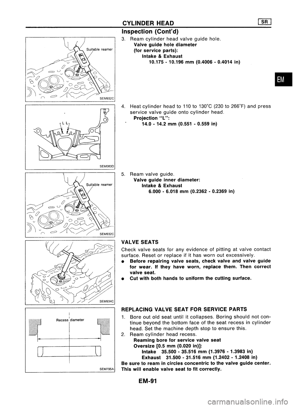
3. Ream cylinder headvalve guide hole.
Valve guide holediameter
(for service parts):
Intake
&
Exhaust
10.175 -10.196 mm(0.4006 -0.4014 in)
4. Heat cylinder headto110 to130°C (230to266°F) andpress
service valveguide ontocylinder head.
Projection
"L":
14.0 -14.2 mm(0.551 -0.559 in)
•
r
I
Recess
I
diameter
I
SEM795A
5.
Ream valveguide.
Valve guide innerdiameter:
Intake
&
Exhaust
6.000 -6.018 mm(0.2362 -0.2369 in)
VALVE SEATS
Check valveseatsforany evidence ofpitting atvalve contact
surface. Resetorreplace ifithas worn outexcessively.
• Before repairing valveseats, checkvalveandvalve guide
for wear. Ifthey have worn, replace them.Thencorrect
valve seat.
• Cut with both hands touniform thecutting surface.
REPLACING VALVESEATFORSERVICE PARTS
1. Bore outoldseat until
it
collapses. Boringshould notcon-
tinue beyond thebottom faceofthe seat recess incylinder
head. Setthemachine depthstoptoensure this.
2. Ream cylinder headrecess.
Reaming boreforservice valveseat
Oversize [0.5mm (0.020 in)]:
Intake 35.500-35.516 mm(1.3976 -1.3983 in)
Exhaust 31.500.31.516 mm(1.2402 -1.2408 in)
Be sure toream incircles concentric tothe valve guide center.
This willenable valveseattofit correctly.
EM-91
Page 1317 of 1701
![NISSAN ALMERA N15 1995 Service Manual
Unit:mm(in)
SEM529DCYLINDER
HEAD
@[]
Installation (Cont'd)
• Apply sealing compound (THREE-BOND No.10or equiva-
lent) toboth ends ofbrackets No.1andNo.5.
Selecting cylinderheadgasket
When NISSAN ALMERA N15 1995 Service Manual
Unit:mm(in)
SEM529DCYLINDER
HEAD
@[]
Installation (Cont'd)
• Apply sealing compound (THREE-BOND No.10or equiva-
lent) toboth ends ofbrackets No.1andNo.5.
Selecting cylinderheadgasket
When](/manual-img/5/57349/w960_57349-1316.png)
Unit:mm(in)
SEM529DCYLINDER
HEAD
@[]
Installation (Cont'd)
• Apply sealing compound (THREE-BOND No.10or equiva-
lent) toboth ends ofbrackets No.1andNo.5.
Selecting cylinderheadgasket
When replacing onlycylinder headgasket, installthesame
grade (Number ofnotches) gasketasthe one formerly used.
Step 1
Measure projection ofpiston tocylinder headsurface.
a) Set dial gauge andneedle oncylinder blockandadjust dial
gauge tozero.
b) Set dial gauge needle atmeasuring pointonpiston, taking
care nottodisturb itszero setting.
c) Rotate crankshaft aroundthetopdead center position.
d) Read andwrite down themaximum value.
e) Reset dialgauge oncylinder blockandconfirm thatzero
setting hasnotbeen disturbed duringmeasurement.
f) Repeat stepsbthrough dfor allmeasuring pointsasillus-
trated andforeach cylinder.
• Besure thatpiston whose projection isbeing measured is
at its TDC.
Step 2
Calculate theaverage valueofmeasurements takenforeach
piston.
Step 3
Calculate theaverage valueofmeasurements forallpistons
from thevalues obtained fromstep2.
Step 4
Round offthe value obtained.
Step 5
Determine requiredthickness ofgasket, referring tochart
A.
EM-138
Page 1613 of 1701

ON-VEHICLESERVICE
Rear Wheel Alignment
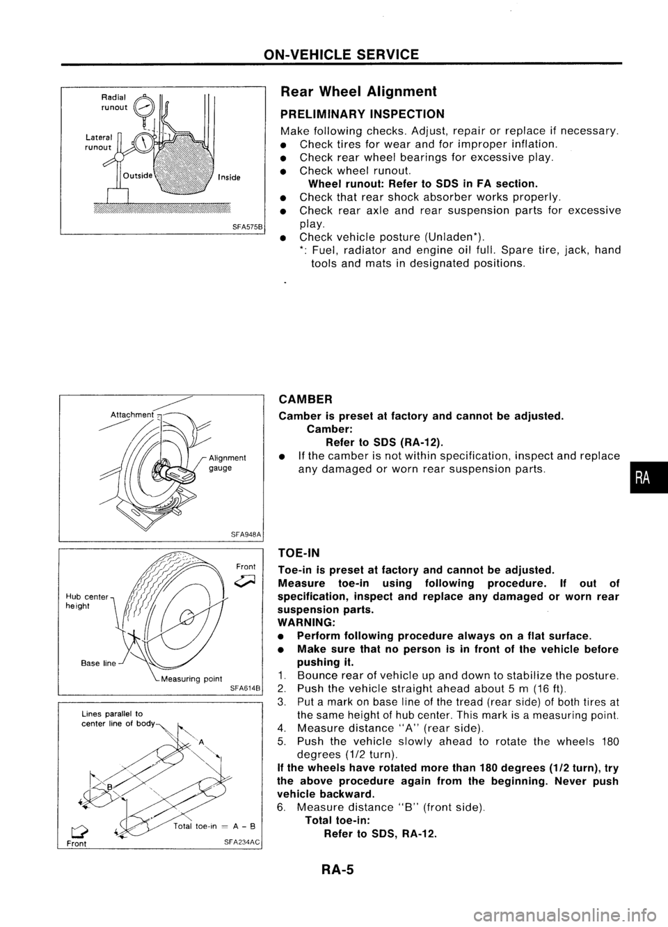
PRELIMINARY INSPECTION
Make following checks.Adjust,repairorreplace ifnecessary.
• Check tiresforwear andforimproper inflation.
• Check rearwheel bearings forexcessive play.
• Check wheelrunout.
Wheel runout: RefertoSOS inFA section.
• Check thatrear shock absorber worksproperly.
• Check rearaxleandrear suspension partsforexcessive
SFA575B
play.
• Check vehicle posture (Unladen*).
*: Fuel, radiator andengine oilfull. Spare tire,jack, hand
tools andmats indesignated positions.
•
CAMBER
Camber ispreset atfactory andcannot beadjusted.
Camber: Refer toSOS (RA-12).
• Ifthe camber isnot within specification, inspectandreplace
any damaged orworn rearsuspension parts.
TOE-IN
Toe-in ispreset atfactory andcannot beadjusted.
Measure toe-inusingfollowing procedure. Ifout of
specification, inspectandreplace anydamaged orworn rear
suspension parts.
WARNING:
• Perform following procedure alwaysonaflat surface.
• Make surethatnoperson isin front ofthe vehicle before
pushing it.
1. Bounce rearofvehicle upand down tostabilize theposture.
2. Push thevehicle straight aheadabout5m (16
ft).
3. Putamark onbase lineofthe tread (rearside) ofboth tires at
the same height ofhub center. Thismark isameasuring point.
4. Measure distance"A"(rear side).
5. Push thevehicle slowlyaheadtorotate thewheels 180
degrees (1/2turn).
If the wheels haverotated morethan180degrees (1/2turn), try
the above procedure againfromthebeginning. Neverpush
vehicle backward.
6. Measure distance"B"(front side).
Total toe-in:
Refer toSOS, RA-12.
Front
SFA948A
SFA614B
SFA234AC
Lines
parallel to
center lineofbOdY~
Q
Front
Hub
center
height
RA-5
Page 1655 of 1701

TROUBLEDIAGNOSES -Supplemental RestraintSystem(SRS)-
Dual AirBag System
Self-diagnosis (Cont'd)
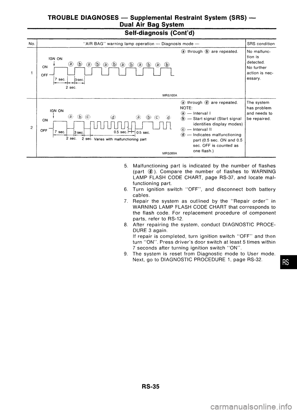
No.
ON
OFF
IGN
ON
t
"AIR
BAG" warning lampoperation -Diagnosis mode-
@
through
@
are repeated.
MRS100A
SRS
condition
No malfunc-
tion is
detected. No further
action isnec-
essary.
2 ON
OFF
IGN
ON
I
7 sec.
@)
@
(c)
3sec.
2 sec. 2sec. Varies withmalfunctioning part
MRS099A
@
through
@
are repeated.
NOTE: @ -
Interval I
@ -
Start signal (Startsignal
identifies displaymodes)
@ -
Interval II
@ -
Indicates malfunctioning
part (0.5sec. ONand 0.5
sec. OFF iscounted as
one flash.) The
system
has problem
and needs to
be repaired.
5. Malfunctioning partisindicated bythe number offlashes
(part
@).
Compare thenumber offlashes toWARNING
LAMP FLASH CODECHART, pageRS-37, andlocate mal-
functioning part.
6. Turn ignition switch"OFF", anddisconnect bothbattery
cables.
7. Repair thesystem asoutlined bythe "Repair order"in
WARNING LAMPFLASH CODECHART thatcorresponds to
the flash code. Forreplacement procedureofcomponent
parts, refertoRS-12.
8. After repairing thesystem, conduct DIAGNOSTIC PROCE-
DURE 3again.
If repair iscompleted, turnignition switch"OFF"andthen
turn "ON". Pressdriver's doorswitch atleast 5times within
7 seconds afterturning ignition switch"ON".
9. The system isreset fromDiagnostic modetoUser mode.
Next, gotoDIAGNOSTIC PROCEDURE 1,page RS-32. •
RS-35