Page 983 of 1701

TROUBLEDIAGNOSIS -General Description
Sensors
~ ECMActuators
~~.~ MEF036D
SEF234G Introduction
The engine hasanECM tocontrol majorsystems suchasfuel
control, ignitioncontrol, idleaircontrol system, etc.The ECM
accepts inputsignals fromsensors andinstantly drivesactua-
tors. Itis essential thatboth input andoutput signals areproper
and stable. Atthe same time,itis important thatthere areno
problems suchasvacuum leaks,fouled sparkplugs, orother
problems withtheengine.
It is much moredifficult todiagnose aproblem thatoccurs
intermittently ratherthancontinuously. Mostintermittent prob-
lems arecaused bypoor electric connections orimproper wir-
ing. Inthis case, careful checking ofsuspected circuitsmay
help prevent thereplacement ofgood parts.
A visual checkonlymaynotfind thecause ofthe problems. A
road testwith CONSULT oracircuit testerconnected shouldbe
performed. Followthe"Work Flow"onthe next page.
Before undertaking actualchecks, takejustafew minutes to
talk with acustomer whoapproaches withadriveability com-
plaint. Thecustomer cansupply goodinformation aboutsuch
problems, especially intermittent ones.Findoutwhat symptoms
are present andunder whatconditions theyoccur. A"Diagnos-
tic Worksheet" liketheexample onEC-267 shouldbeused.
Start yourdiagnosis bylooking for"conventional" problems
first. Thiswillhelp troubleshoot driveabilityproblemsonan
electronically controlledenginevehicle.
EC-264
Page 1102 of 1701
relay-2ENGINE
ANDEMISSION CONTROLOVERALLSYSTEM
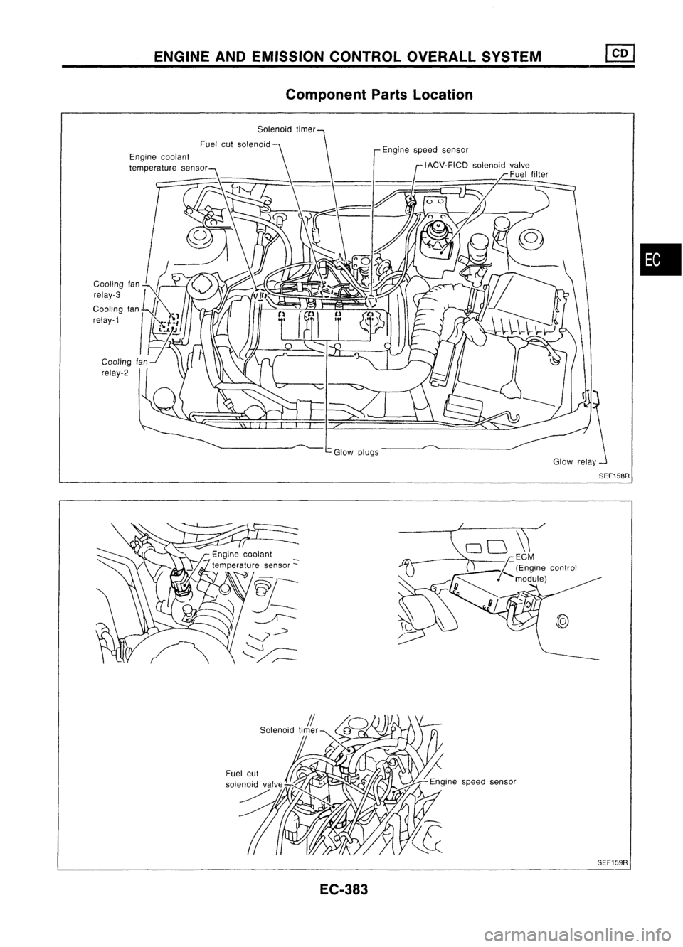
Component PartsLocation
Engine coolant
temperature sensor
Glowplugs
•
EC-383 SEF159R
Page 1109 of 1701
TROUBLEDIAGNOSES
Quick-glow System
SYSTEM DESCRIPTION
Ignition key
Engine coolant temperature sensorKey-in
switch andkeyposition
Engine coolant temperature
ECM
(Engine
control
module) Glow
relay
Glow lamp Glow
plugs
Ignition START[~
~
switch
~~[ I
11
I
1iI
Key
~
switch OUT
-II-
T,
I
!
I
I-l
Key ONe
n
Hn
JTl-
.1"l....!:.1L-
~
timer
OFF
Ir1
To
I
UL
HTo
HT'o
Lamp ON
[
..Lfl
o~~
I
I-.J
TL
I
~
I
I-l
TL
I
I
I
I
I
HTL
I-l
T'L
Relay OFF
[j
I_
L-
r--L
.f"l.-.JL
~
T.
"'
II
I
II
~
1r;,1
I II I
I,
Glow plug
temperature
Normaloperation
Operationafter
key timer isOFF Leaving
keyin
ON position Repeating
keyIN
and OUT Repeating
keyON
and OFF
TL
=
T,-T,
when T,-0.5 >T,
TL
= T,
when T,-0.5 ~T,
;a;
To
TL
=.
T,
when To
<
T, T'o
~80% ofTo
when T.
5':
3sec.
T',
=.
T,
T',
=.
T,
SEC550B
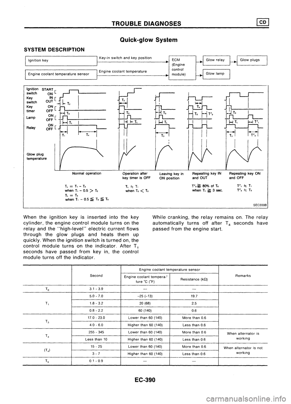
When theignition keyisinserted intothekey
cylinder, theengine control module turnsonthe
relay andthe"high-level" electriccurrentflows
through theglow plugs andheats themup
quickly. Whentheignition switchisturned on,the
control module turnsonthe indicator. AfterT
1
seconds havepassed fromkeyin,the control
module turnsoffthe indicator. While
cranking, therelay remains on.The relay
automatically turnsoffafter T
4
seconds have
passed fromtheengine start.
Engine coolant temperature sensor
Second Enginecoolant tempera-' Remarks
ture 'C('F) Resistance
(kQ)
To
3.1
-3.9
- -
5.0 -7.0 -25(-13)
19.7
T,
1.8
-3.2
20(68)
2.5
0.8 -2.2 60(140)
0.6
17.0 -23.0
Lowerthan
60(140)
Morethan
0.6
T
3
40-6.0
Higherthan
60(140)
Lessthan
0.6
255 -345
Lowerthan
60(140)
Morethan
0.6
Whenalternator is
T
4
working
Less than
10
Higherthan
60(140)
Lessthan
0.6
15 -25
Lowerthan
60(140)
Morethan
0.6
Whenalternator isnot
(T
4)
working
3 -7
Higherthan
60(140)
Lessthan
0.6
T
5
0.1-0.9
- -
EC-390
Page 1194 of 1701
COMPRESSIONPRESSURE
20
mm
(O.79 In)dls.
Use compressor testerwhose end(rubber
portion) isless than 20mm (0.79 in)dia.
Otherwise, itmay becaught bycylinder
head during removal.
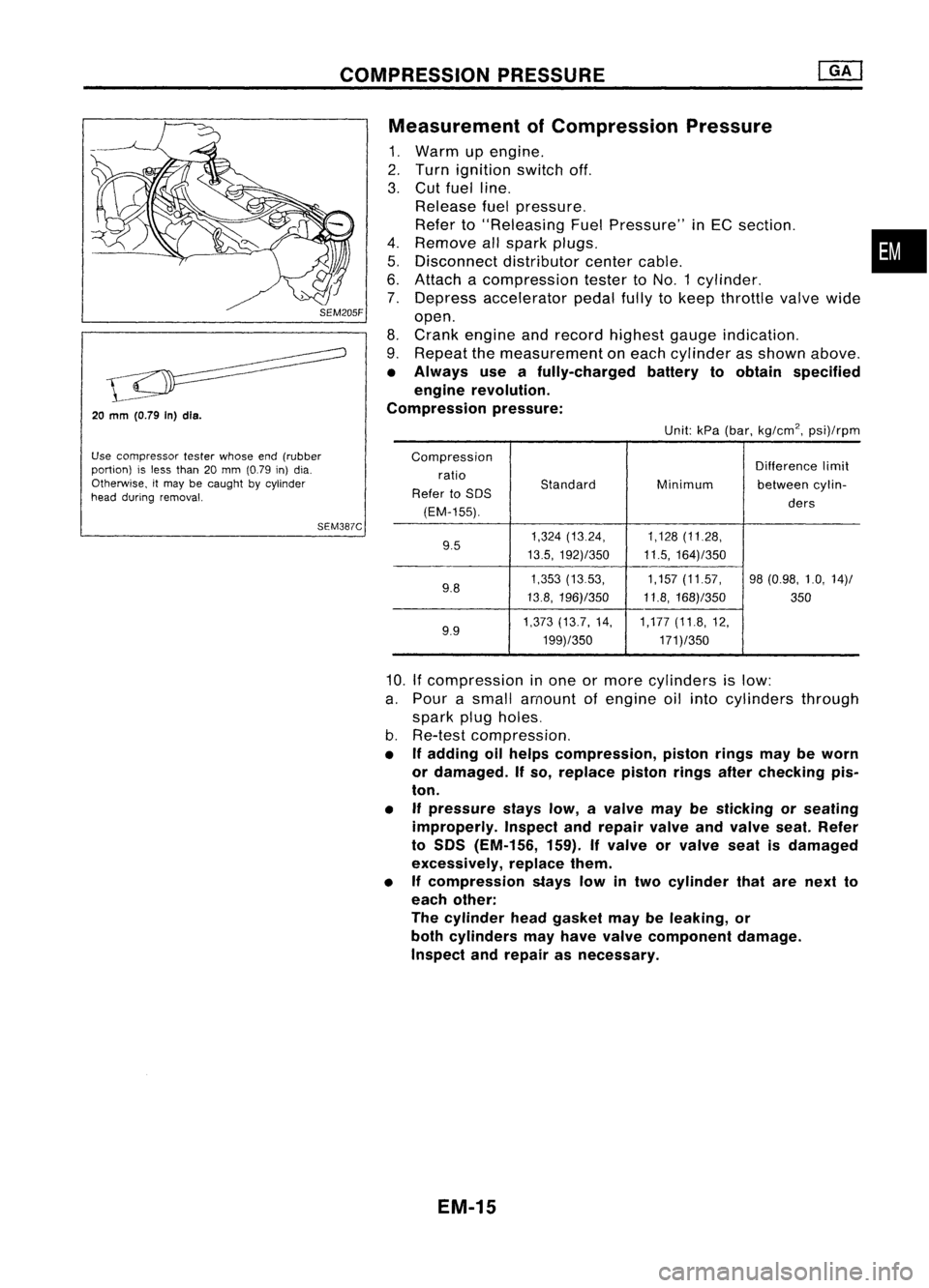
SEM387CMeasurement
ofCompression Pressure
1. Warm upengine.
2. Turn ignition switchoff.
3. Cut fuel line.
Release fuelpressure.
Refer to"Releasing FuelPressure" inEC section. •
4. Remove allspark plugs.
5. Disconnect distributorcentercable.
6. Attach acompression testertoNO.1 cylinder.
7. Depress accelerator pedalfullytokeep throttle valvewide
open.
8. Crank engine andrecord highest gaugeindication.
9. Repeat themeasurement oneach cylinder asshown above.
• Always useafully-charged batterytoobtain specified
engine revolution.
Compression pressure:
Unit:kPa(bar, kg/cm
2,
psi)/rpm
Compression Differencelimit
ratio
Standard
Refer toSOS Minimum
betweencylin-
(EM-155). ders
9.5 1,324
(13.24, 1,128(11.28,
13.5, 192)/350 11.5,164)/350
9.8 1,353
(1353, 1,157(11.57, 98(0.98, 1.0,14)/
13.8, 196)/350 11.8,168)/350
350
9.9 1,373
(13.7, 14, 1,177(11.8,12,
199)/350 171)/350
10.
If
compression inone ormore cylinders islow:
a. Pour asmall amount ofengine oilinto cylinders through
spark plugholes.
b. Re-test compression,
• Ifadding oilhelps compression, pistonringsmaybeworn
or damaged. Ifso, replace pistonringsafterchecking pis-
ton.
• Ifpressure stayslow,avalve maybesticking orseating
improperly. Inspectandrepair valveandvalve seat.Refer
to SOS (EM-156, 159).Ifvalve orvalve seatisdamaged
excessively, replacethem.
• Ifcompression stayslowintwo cylinder thatarenext to
each other:
The cylinder headgasket maybeleaking, or
both cylinders mayhave valve component damage.
Inspect andrepair asnecessary.
EM-15
Page 1199 of 1701
TIMINGCHAIN
Without
VTC
CAUTION:
• After removing timingchain,donot turn crankshaft and
camshaft separately, orvalves willstrike piston heads.
• When installing camshafts, chaintensioner, oilseals, or
other sliding parts,lubricate contacting surfaceswithnew
engine oil.
• Apply newengine oiltobolt threads andseat surfaces when
installing cylinderhead,camshaft sprocket,crankshaft
pulley, andcamshaft brackets.
Removal
1. Drain engine coolant fromradiator andcylinder block.
Be careful nottospill coolant ondrive belts.
2. Release fuelpressure. '
Refer to"Releasing FuelPressure" inEG section.
3.. Remove thefollowing belts.
• Power steering pumpdrivebelt
• Alternator drivebelt
4. Remove powersteering pulleyandpump withbracket.
5. Remove airduct tointake manifold collector.
6. Remove frontright-side wheel.
7. Remove frontright-side splashcover.
8. Remove frontundercovers.
9. Remove frontexhaust tube.
10. Remove cylinderheadfrontmounting bracket.
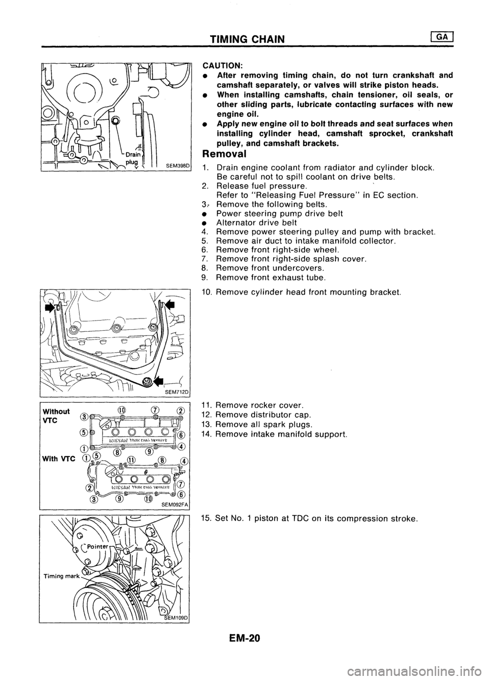
11. Remove rockercover.
12. Remove distributor cap.
13. Remove allspark plugs.
14. Remove intakemanifold support.
15. Set NO.1 piston at
TOG
onitscompression stroke.
EM-20
Page 1208 of 1701

~(0.39)
~1-J--10 (0.39)
* -\
3 (0.12)
Z~
Liquid
gasket
SEM59BEA TIMING
CHAIN
Installation (Cont'd)
29. Apply liquidgasket torocker covergasket.
•
W")
WithoutVTC
Engine front
Unit: mm(in)
~(0.39)
~1-J--10 (0.39)
* -\
3 (0.12)
Z~
Liquid
gasket
SEM59BEA TIMING
CHAIN
Installation (Cont'd)
29. Apply liquidgasket torocker covergasket.
•
With VTC
Cylinderhead
'l:tJ
~ /2.0-3.0mm
Cylinder headfront cover
(0.079-0.118 In)
With
VTC
28. Apply liquidgasket tomating surfaces ofthe cylinder head
and cylinder headfrontcovers showninthe figure.
With VTC
Engine front
Unit: mm(in)
SEM091F
7~'\
\ ..... -4'
~-'?
~'0391
~10 (0.39)
*
--1
3 (0.12)
Zr.a
liquid
gasket
SEM111F
29.
Apply liquidgasket torocker covergasket.
Without VTC
With VTC
30.
Install rocker coverandtighten innumerical orderasshown
in the figure.
31. Install allspark plugsandleads.
32. Install engine frontmounting bracketandmounting.
33. Install frontexhaust tube.
34. Install frontundercover.
35. Install frontright.splash cover.
36. Install frontrightwheel.
37. Install aircleaner.
38. Install power steering pulleyandpump withbracket.
To check power steering fluid,refertoMA section ("Check-
ing Power Steering FluidandLines", "CHASSIS ANDBODY
MAINTENANCE").
39. Drive belts.
For adjusting drivebeltdeflection, refertoMA section
("Checking DriveBelts", "ENGINE MAINTENANCE").
EM-29
Page 1220 of 1701
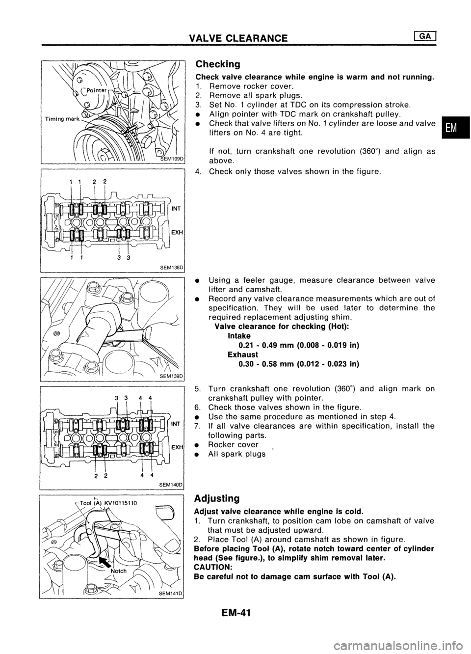
VALVECLEARANCE
1 1 22
2 2 44
SEM140D Checking
Check valveclearance whileengine iswarm andnotrunning.
1. Remove rockercover.
2. Remove allspark plugs.
3. Set
NO.1
cylinder atTOC onitscompression stroke.
• Align pointer withTOC mark oncrankshaft pulley.
• Check thatvalve lifters on
NO.1
cylinder areloose andvalve
lifters on
NO.4
aretight.
If not, turn crankshaft onerevolution (360°)andalign as
above.
4. Check onlythose valves showninthe figure.
• Using afeeler gauge, measure clearance betweenvalve
lifter andcamshaft.
• Record anyvalve clearance measurements whichareoutof
specification. Theywillbeused latertodetermine the
required replacement adjustingshim.
Valve clearance forchecking (Hot):
Intake 0.21 -0.49 mm(0.008 .0.019 in)
Exhaust 0.30. 0.58mm(0.012 -0.023 in)
5. Turn crankshaft onerevolution (360°)andalign markon
crankshaft pulleywithpointer.
6. Check thosevalves shown inthe figure.
• Use thesame procedure asmentioned instep 4.
7. Ifall valve clearances arewithin specification, installthe
following parts.
• Rocker cover
• Allspark plugs
•
"-
Tool (A}KV10115110
,
SEM141DAdjusting
Adjust valveclearance whileengine iscold.
1. Turn crankshaft, toposition camlobeoncamshaft ofvalve
that must beadjusted upward.
2. Place Tool(A)around camshaft asshown infigure.
Before placing Tool(A),rotate notchtoward centerofcylinder
head (Seefigure.), tosimplify shimremoval later.
CAUTION: Be careful nottodamage camsurface withTool (A).
EM-41
Page 1241 of 1701
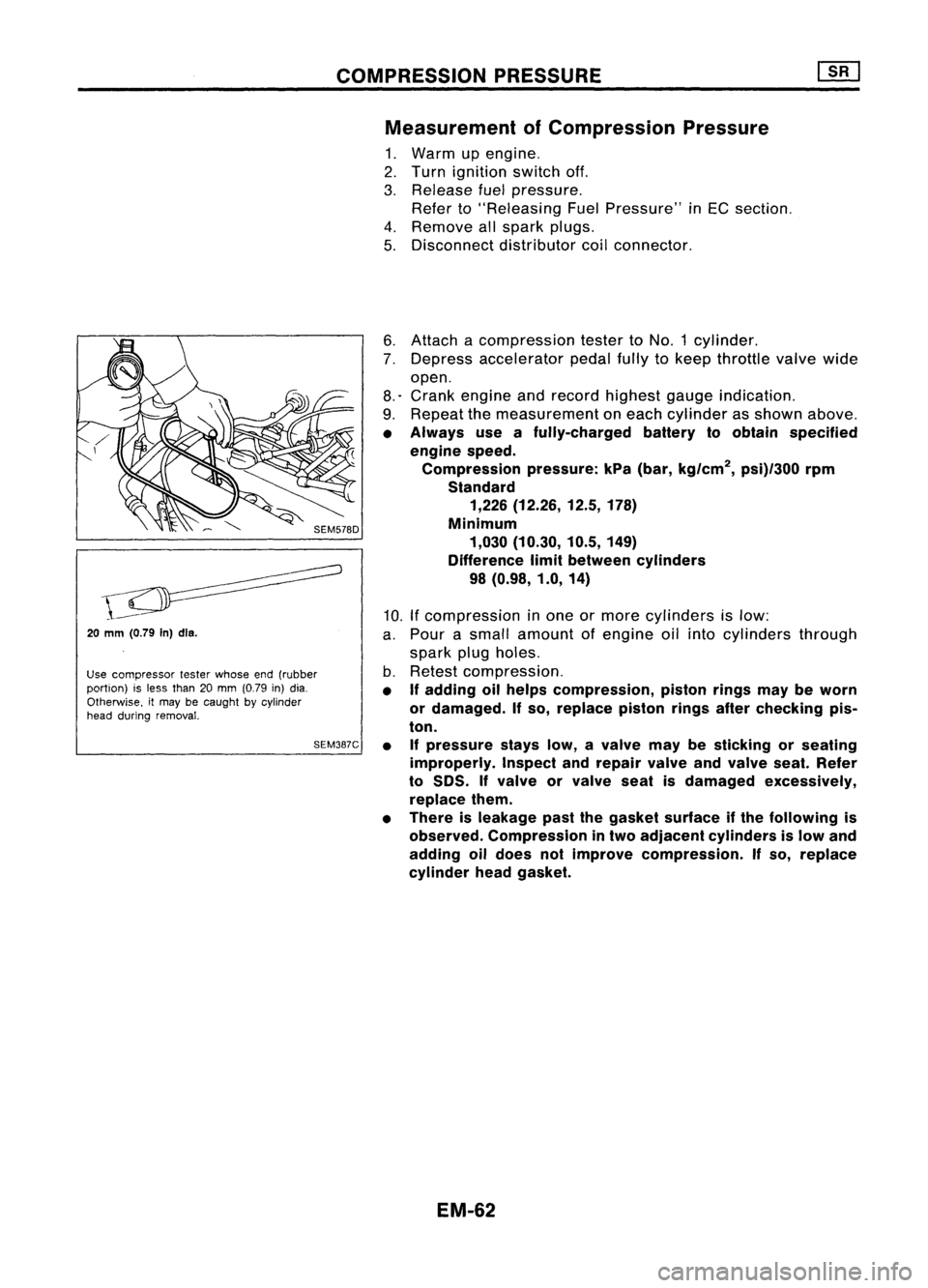
COMPRESSIONPRESSURE
Measurement ofCompression Pressure
1. Warm upengine.
2. Turn ignition switchoff.
3. Release fuelpressure.
Refer to"Releasing FuelPressure" inEC section.
4. Remove allspark plugs.
5. Disconnect distributorcoilconnector.
20
mm (0.79
In)dls.
Use compressor testerwhose end(rubber
portion) isless than 20mm (0.79 in)dia.
Otherwise. itmay becaught bycylinder
head during removal.
SEM387C6.
Attach acompression testertoNO.1 cylinder.
7. Depress accelerator pedalfullytokeep throttle valvewide
open.
8.' Crank engine andrecord highest gaugeindication.
9. Repeat themeasurement oneach cylinder asshown above.
• Always useafully-charged batterytoobtain specified
engine speed.
Compression pressure:kPa(bar, kg/cm
2,
psi)/300 rpm
Standard 1,226 (12.26, 12.5,178)
Minimum 1,030 (10.30, 10.5,149)
Difference limitbetween cylinders
98 (0.98, 1.0,14)
10. Ifcompression inone ormore cylinders islow:
a. Pour asmall amount ofengine oilinto cylinders through
spark plugholes.
b. Retest compression.
• If
adding oilhelps compression, pistonringsmaybeworn
or damaged.
If
so, replace pistonringsafterchecking pis-
ton.
• Ifpressure stayslow,avalve maybesticking orseating
improperly. Inspectandrepair valveandvalve seat.Refer
to
50S.
If
valve orvalve seatisdamaged excessively,
replace them.
• There isleakage pastthegasket surface ifthe following is
observed. Compression intwo adjacent cylinders islow and
adding oildoes notimprove compression.
If
so, replace
cylinder headgasket.
EM-62