1995 NISSAN ALMERA N15 dtc 21
[x] Cancel search: dtc 21Page 720 of 1701
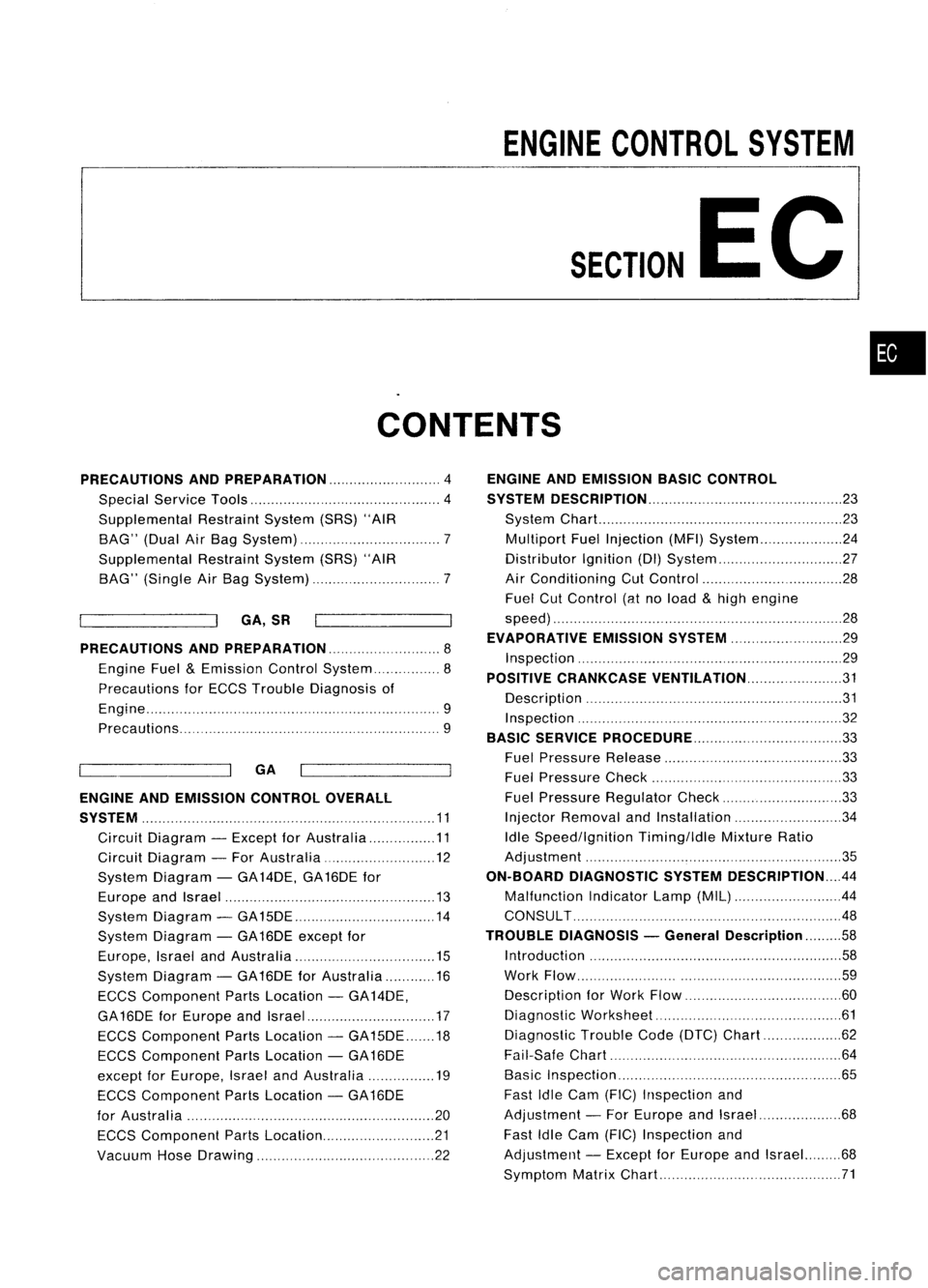
ENGINECONTROL SYSTEM
SECTION
EC
CONTENTS
•
PRECAUTIONS ANDPREPARATION
4
Special Service Tools 4
Supplemental RestraintSystem(SRS)"AIR
BAG" (DualAirBag System) 7
Supplemental RestraintSystem(SRS)"AIR
BAG" (Single AirBag System) 7
GA,SR
PRECAUTIONS ANDPREPARATION
8
Engine Fuel
&
Emission ControlSystem 8
Precautions forECCS Trouble Diagnosis of
Engine 9
Precautions 9
ENGINE ANDEMISSION CONTROLOVERALL
SYSTEM 11
Circuit Diagram -Except forAustralia 11
Circuit Diagram -For Australia 12
System Diagram -GA 14DE, GA16DE for
Europe andIsrael 13
System Diagram -GA15DE 14
System Diagram -GA 16DE except for
Europe, IsraelandAustralia 15
System Diagram -GA 16DE forAustralia 16
ECCS Component PartsLocation -GA 14DE,
GA 16DE forEurope andIsrael 17
ECCS Component PartsLocation -GA15DE 18
ECCS Component PartsLocation -GA 16DE
except forEurope, IsraelandAustralia 19
ECCS Component PartsLocation -GA 16DE
for Austral ia 20
ECCS Component PartsLocation 21
Vacuum HoseDrawing 22
c=
~
GA
ENGINE
ANDEMISSION BASICCONTROL
SYSTEM DESCRiPTION 23
System Chart.. 23
Multiport FuelInjection (MFI)System 24
Distributor Ignition(01)System 27
Air Conditioning CutControl 28
Fuel CutControl (atnoload &high engine
speed) 28
EVAPORATIVE EMISSIONSYSTEM
29
Inspection 29
POSITIVE CRANKCASE VENTILATION 31
Description 31
Inspection 32
BASIC SERVICE PROCEDURE 33
Fuel Pressure Release 33
Fuel Pressure Check 33
Fuel Pressure Regulator Check 33
Injector Removal andInstallation 34
Idle Speed/lgnition Timing/ldleMixtureRatio
Adjustment ,35
ON-BOARD DIAGNOSTIC SYSTEMDESCRIPTION .44
Malfunction IndicatorLamp(MIL) 44
CONSULT .48
TROUBLE DIAGNOSIS -General Description
58
Introduction 58
Work Flow 59
Description forWork Flow 60
Diagnostic Worksheet 61
Diagnostic TroubleCode(DTC) Chart 62
Fail-Safe Chart 64
Basic Inspection 65
Fast IdleCam (FIC) Inspection and
Adjustment -For Europe andIsrael 68
Fast IdleCam (FIC) Inspection and
Adjustment -Except forEurope andIsrael. 68
Symptom MatrixChart 71
Page 721 of 1701
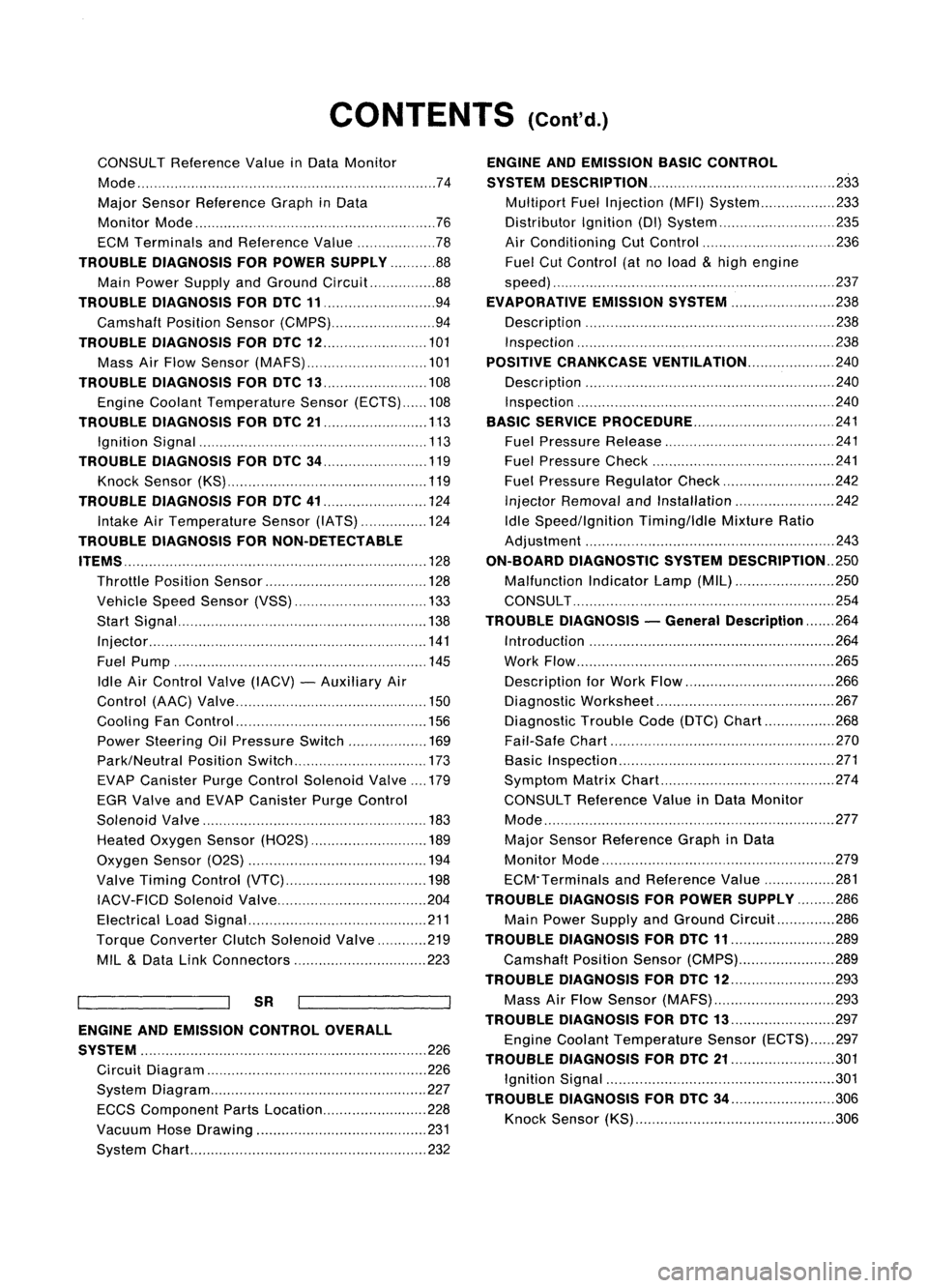
CONTENTS(Cont'd.)
CONSULT Reference ValueinData Monitor
Mode 74
Major Sensor Reference GraphinData
Monitor Mode 76
ECM Terminals andReference Value 78
TROUBLE DIAGNOSIS FORPOWER SUPPLY 88
Main Power Supply andGround Circuit.. 88
TROUBLE DIAGNOSIS FORDTC11 94
Camshaft PositionSensor(CMPS) 94
TROUBLE DIAGNOSIS FORDTC
12 101
Mass AirFlow Sensor (MAFS) 101
TROUBLE DIAGNOSIS FORDTC
13 108
Engine Coolant Temperature Sensor(ECTS) 108
TROUBLE DIAGNOSIS FORDTC
21 113
Ignition Signal 113
TROUBLE DIAGNOSIS FORDTC
34 119
Knock Sensor (KS) 119
TROUBLE DIAGNOSIS FORDTC
41 124
Intake AirTemperature Sensor(IATS) 124
TROUBLE DIAGNOSIS FORNON-DETECTABLE
ITEMS , '"
.128
Throttle Position Sensor 128
Vehicle SpeedSensor (VSS) 133
Start Signal 138
Injector 141
Fuel Pump 145
Idle AirControl Valve(IACV) -Auxiliary Air
Control (AAC)Valve 150
Cooling FanControl 156
Power Steering OilPressure Switch 169
Park/Neutral PositionSwitch 173
EVAP Canister PurgeControl Solenoid Valve179
EGR Valve andEVAP Canister PurgeControl
Solenoid Valve 183
Heated Oxygen Sensor(H02S) 189
Oxygen Sensor(02S) 194
Valve Timing Control (VTC) 198
IACV-FICD SolenoidValve 204
Electrical LoadSignal 211
Torque Converter ClutchSolenoid Valve 219
MIL
&
Data LinkConnectors 223
SR
ENGINE ANDEMISSION CONTROL OVERALL
SYSTE M
226
Circuit Diagram 226
System Diagram 227
ECCS Component PartsLocation 228
Vacuum HoseDrawing 231
System Chart... 232
ENGINE
ANDEMISSION BASICCONTROL
SYSTEM DESCRiPTION
233
Multipart FuelInjection (MFI)System 233
Distributor Ignition
(01)
System 235
Air Conditioning CutControl 236
Fuel CutControl (atnoload
&
high engine
speed) 237
EVAPORATIVE EMISSIONSYSTEM
238
Description 238
Inspection 238
POSITIVE CRANKCASE VENTILATION
240
Description 240
Inspection 240
BASIC SERVICE
PROCEDURE 241
Fuel Pressure Release 241
Fuel Pressure Check 241
Fuel Pressure Regulator Check 242
Injector Removal andInstallation 242
Idle Speed/Ignition Timing/IdleMixtureRatio
Adjustment 243
ON-BOARD DIAGNOSTIC SYSTEMDESCRIPTION ..250
Malfunction IndicatorLamp(MIL) 250
CONSULT 254
TROUBLE DIAGNOSIS -General Description
264
Introduction 264
Work Flow 265
Description forWork Flow 266
Diagnostic Worksheet 267
Diagnostic TroubleCode(DTC) Chart 268
Fail-Safe Chart 270
Basic Inspection 271
Symptom MatrixChart. 274
CONSULT Reference ValueinData Monitor
Mode 277
Major Sensor Reference GraphinData
Monitor Mode 279
ECM"Terminals andReference Value 281
TROUBLE DIAGNOSIS FORPOWER SUPPLY
286
Main Power Supply andGround Circuit.. 286
TROUBLE DIAGNOSIS FORDTC
11 289
Camshaft PositionSensor(CMPS) 289
TROUBLE DIAGNOSIS FORDTC
12 293
Mass AirFlow Sensor (MAFS) 293
TROUBLE DIAGNOSIS FORDTC
13 297
Engine Coolant Temperature Sensor(ECTS) 297
TROUBLE DIAGNOSIS FORDTC
21 301
Ignition Signal 301
TROUBLE DIAGNOSIS FORDTC
34 306
Knock Sensor (KS) 306
Page 722 of 1701
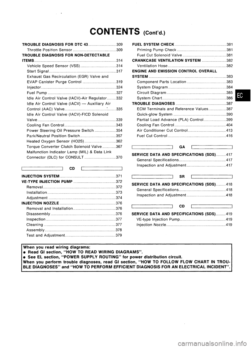
CONTENTS(Cont'd.)
TROUBLE DIAGNOSIS FORDTC
43 309
Throttle Position Sensor 309
TROUBLE DIAGNOSIS FORNON-DETECTABLE
ITEMS
314
Vehicle SpeedSensor (VSS) 314
Start Signal 317
Exhaust GasRecirculation (EGR)Valveand
EVAP Canister PurgeControl 319
Injector 324
Fuel Pump 327
Idle AirControl Valve(IACV)-Air Regulator 332
Idle AirControl Valve(IACV) -Auxiliary Air
Control (AAC)Valve :335
Idle AirControl Valve(IACV)-FICD Solenoid
Valve '"339
Cooling FanControl 343
Power Steering OilPressure Switch 354
Park/Neutral PositionSwitch 357
Heated Oxygen Sensor(H02S) 362
Torque
Converter
ClutchSolenoid Valve 367
Malfunction IndicatorLamp(MIL)
&
Data Link
Connector (DLC)forCONSULT 370
CD
INJECTION SYSTEM
371
VE.TYPE INJECTION PUMP
372
Removal 372
Installation 373
Adjustment 374
INJECTION NOZZLE
376
Removal andInstallation 376
Disassembly 376
Inspection 377
Cleaning 377
Assembly 378
Test andAdjustment 379
FUEL
SYSTEM CHECK
381
Priming PumpCheck 381
Fuel CutSolenoid Valve 381
CRANKCASE VENTILATION SYSTEM
382
Ventilation Hose 382
ENGINE ANDEMISSION CONTROLOVERALL
SYSTEM
383
Component PartsLocation 383
System Diagram 384
Circuit Diagram ,385
System Chart. 386
TROUBLE DIAGNOSES
387
ECM Terminals andReference Values 387
Quick-glow System 390
Partial LoadAdvance (PLA)Control 399
Cooling FanControl 404
Air Conditioner CutControl 413
Fuel CutControl 416
GA
SERVICE DATAANDSPECIFICATIONS
(505).417
General Specifications 417
Inspection andAdjustment.. 417
SR
SERVICE DATAANDSPECIFICATIONS
(505).418
General Specifications 418
Inspection andAdjustment.. .418
CD
SERVICE DATAANDSPECIFICATIONS
(505).419
VE-type Injection Pump 419
Injection Nozzle 419
•
When youread wiring diagrams:
• Read GIsection, "HOWTOREAD WIRING DIAGRAMS" .
• See Elsection, "POWER SUPPLYROUTING" forpower distribution circuit.
When youperform troublediagnoses, readGIsection, "HOWTOFOllOW FLOWCHART INTROU-
BLE DIAGNOSES" and"HOW TOPERFORM EFFICIENT DIAGNOSIS FORANELECTRICAL INCIDENT".
Page 729 of 1701
PRECAUTIONSANDPREPARATION
I
GA, SR
I
Precautions (Cont'd)
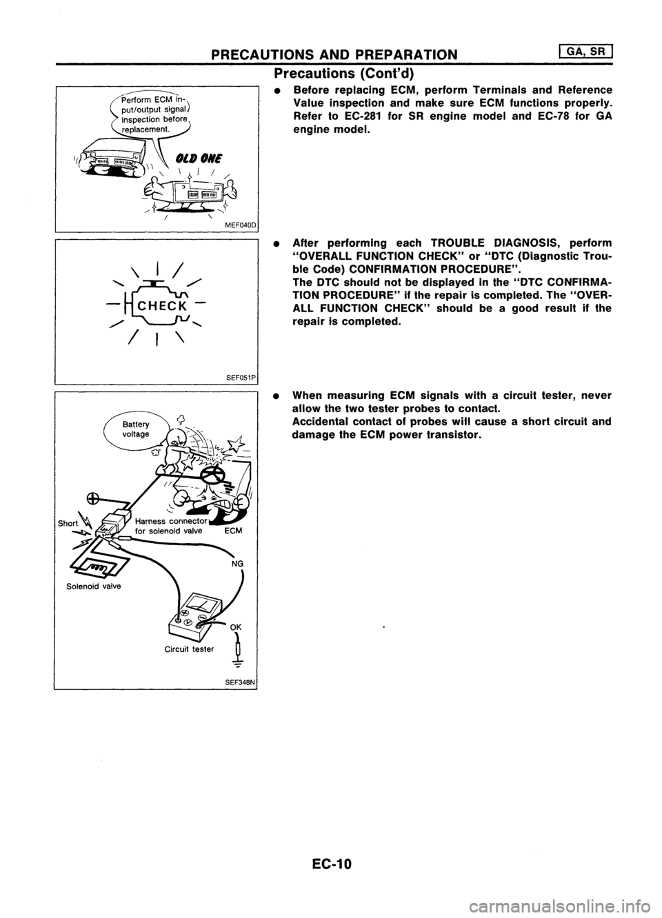
• Before replacing ECM,perform Terminals andReference
Value inspection andmake sureECM functions properly.
Refer toEC-281 forSR engine modelandEC-78 forGA
engine model.
/
"
MEF040D
\ I/
'~/"
- CHECK-
/
.......
/
,
\
SEF051P
NG
@~ )
~K
Circuit tester
.1
SEF34BN
•
After performing eachTROUBLE DIAGNOSIS, perform
"OVERALL FUNCTIONCHECK"or"DTC (Diagnostic Trou-
ble Code) CONFIRMATION PROCEDURE".
The DTC should notbedisplayed inthe "DTC CONFIRMA-
TION PROCEDURE" ifthe repair iscompleted. The"OVER-
ALL FUNCTION CHECK"shouldbeagood result ifthe
repair iscompleted.
• When measuring ECMsignals withacircuit tester, never
allow thetwo tester probes tocontact.
Accidental contactofprobes willcause ashort circuit and
damage theECM power transistor.
EC-10
Page 765 of 1701
ON-BOARDDIAGNOSTIC SYSTEMDESCRIPTION @KJ
Malfunction Indicatorlamp(Mil)(Cont'd)
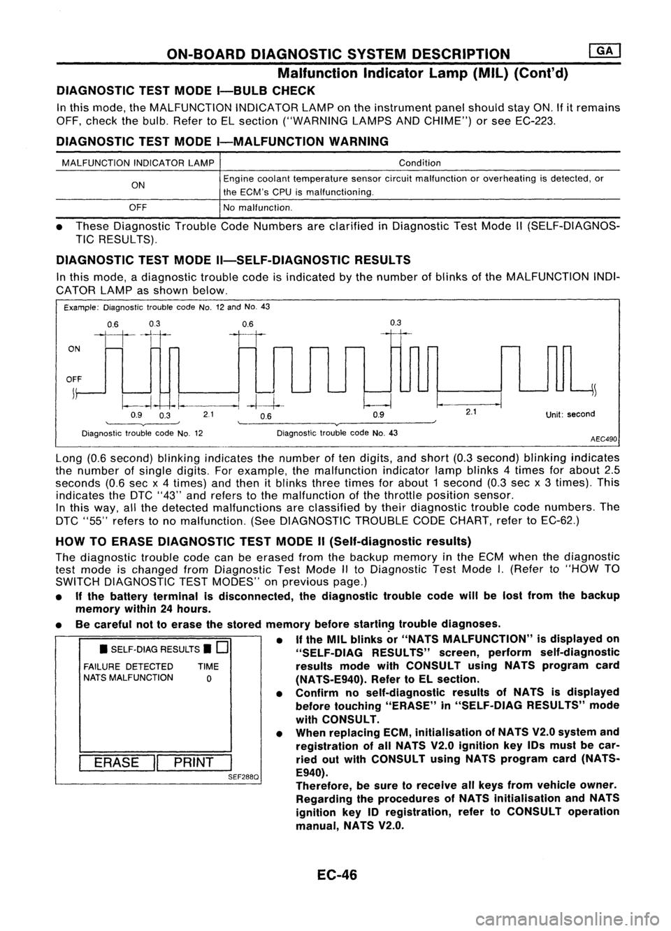
DIAGNOSTIC TESTMODE I-BULB CHECK
In this mode, theMALFUNCTION INDICATORLAMPonthe instrument panelshould stayON.Ifitremains
OFF, check thebulb. Refer toEL section ("WARNING LAMPSANDCHIME") orsee EC-223.
DIAGNOSTIC TESTMODE I-MALFUNCTION WARNING
MALFUNCTION INDICATORLAMP
ON
OFF Condition
Engine coolant temperature sensorcircuitmalfunction oroverheating isdetected, or
the ECM's CPUismalfunctioning.
No malfunction.
• These Diagnostic TroubleCodeNumbers areclarified inDiagnostic TestMode II(SELF-DIAGNOS-
TIC RESULTS).
DIAGNOSTIC TESTMODE II-SELF-DIAGNOSTIC RESULTS
In this mode, adiagnostic troublecodeisindicated bythe number ofblinks ofthe MALFUNCTION INDI-
CATOR LAMPasshown below.
Example: Diagnostic troublecodeNo.12and No.43
ON
0.6
03
111-'1
0.6
II
0.3
OFF
j
~
~~ -I.
--.1
-4--1--
Q9 O~ 21 OB Q9
'--------v----' '--------v------~
Diagnostic troublecodeNo.12 DiagnostictroublecodeNo.43
2.1
Unit:second
AEC490
• SELF-DIAG RESULTS.
0
FAILURE DETECTED TIME
NATS MALFUNCTION
0
I
ERASE
II
PRINT
I
SEF288Q
Long
(0.6second) blinkingindicates thenumber often digits, andshort (0.3second) blinkingindicates
the number ofsingle digits. Forexample, themalfunction indicatorlampblinks 4times forabout 2.5
seconds (0.6secx4 times) andthen itblinks threetimes forabout 1second (0.3secx3 times). This
indicates theDTC "43" andrefers tothe malfunction ofthe throttle position sensor.
In this way, allthe detected malfunctions areclassified bytheir diagnostic troublecodenumbers. The
DTC "55" refers tono malfunction. (SeeDIAGNOSTIC TROUBLECODECHART, refertoEC-62.)
HOW TOERASE DIAGNOSTIC TESTMODE II(Self-diagnostic results)
The diagnostic troublecodecanbeerased fromthebackup memory inthe ECM when thediagnostic
test mode ischanged fromDiagnostic TestMode IIto Diagnostic TestMode
I.
(Refer to"HOW TO
SWITCH DIAGNOSTIC TESTMODES" onprevious page.)
• Ifthe battery terminal isdisconnected, thediagnostic troublecodewillbelost from thebackup
memory within24hours.
• Becareful nottoerase thestored memory before
startin~
troublediagnoses.
• If
the MIL blinks or"NATS MALFUNCTION" isdisplayed on
"SELF-OIAG RESULTS"screen,perform self-diagnostic
results modewithCONSULT usingNATS program card
(NATS-E940). RefertoEL section.
• Confirm noself-diagnostic resultsofNATS isdisplayed
before touching "ERASE" in"SELF-DIAG RESULTS"mode
with CONSULT.
• When replacing ECM,initialisation ofNATS V2.0system and
registration ofall NATS V2.0ignition key10smust becar-
ried outwith CONSULT usingNATS program card(NATS-
E940).
Therefore, besure toreceive allkeys from vehicle owner.
Regarding theprocedures ofNATS initialisation andNATS
ignition key10registration, refertoCONSULT operation
manual, NATS V2.0.
EC-46
Page 770 of 1701
ON-BOARDDIAGNOSTIC SYSTEMDESCRIPTION
CONSULT (ConI'd)
SELF-DIAGNOSTIC MODE
Regarding itemsdetected in"SELF-DIAG RESULTS"mode,referto"Diagnostic TroubleCode(DTC)
Chart" (RefertoEC-62.)
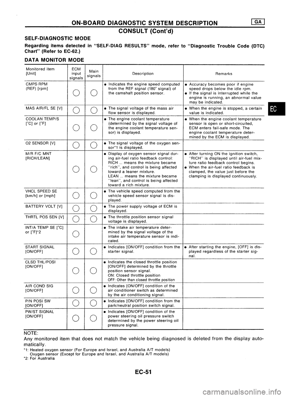
DATA MONITOR MODE
Monitored item ECM
Main
[Unit] input
signals Description
Remarks
signals
CMPS.RPM •Indicates theengine speedcomputed •Accuracy becomespoorifengine
(REF) [rpm]
00
from
theREF signal (180'signal) of
speeddropsbelow theidle rpm.
the camshaft positionsensor.
•Ifthe signal isinterrupted whilethe
engine isrunning, anabnormal value
may beindicated .
MAS AIR/FL SE[V]
0 0
•
The signal voltage ofthe mass air
•When theengine isstopped, acertain
flow sensor isdisplayed .
valueisindicated.
COOLAN TEMP/S
•The engine coolant temperature •When theengine coolant temperature
['C] or['F]
00
(determined
bythe signal voltage of
sensorisopen orshort-circuited,
the engine coolant temperature sen-ECMenters fail-safe mode.The
sor) isdisplayed.
enginecoolant temperature deter-
mined bythe ECM isdisplayed .
02 SENSOR [V]
00
•
The signal voltage ofthe oxygen sen-
sor*1 isdisplayed .
M/R F/CMNT •
Display ofoxygen sensorsignaldur-
•After turning ONthe ignition switch,
[RICH/LEAN] ingair-fuel ratiofeedback control: "RICH"isdisplayed untilair-fuel mix-
RICH ...means themixture became
tureratio feedback controlbegins.
0 0
"rich",
andcontrol isbeing affected •When theair-fuel ratiofeedback is
toward aleaner mixture.
clamped,thevalue justbefore the
LEAN ...means themixture became clampingisdisplayed continuously.
"lean", andcontrol isbeing affected
toward arich mixture .
VHCL SPEED SE
00
•
The vehicle speedcomputed fromthe
[km/h] or[mph] vehicle
speedsensor signalisdis-
played .
BATTERY VOLT[V]
0 0
•
The power supply voltage ofECM is
displayed .
THRTL POSSEN[V]
0 0
•
The throttle position sensorsignal
voltage isdisplayed.
INT/A TEMP SE['C] •The intake airtemperature deter-
or ['F]*2
0
mined
bythe signal voltage ofthe
intake airtemperature sensorisindi-
cated .
START SIGNAL
00
•
Indicates [ON/OFF] conditionfromthe•After starting theengine, [OFF]isdis-
[ON/OFF] startersignal. playedregardless ofthe starter sig-
nal.
CLSD THLIPOSI •Indicates theclosed throttle position
[ON/OFF]
00
[ON/OFF]
determined bythe throttle
position sensorsignal.
ON: Closed throttle position
OFF: Other thanclosed throttle position
AIR COND SIG
00
•
Indicates [ON/OFF] conditionofthe
[ON/OFF] air
conditioner switchasdetermined
by the airconditioning signal.
PIN POSI SW
00
•
Indicates [ON/OFF] conditionfromthe
[ON/OFF] park/neutralpositionswitchsignal.
PW/ST SIGNAL •
Indicates [ON/OFF] conditionofthe
[ON/OFF]
00
power
steering oilpressure switch
determined bythe power steering oil
pressure signal.
NOTE:
Any monitored itemthatdoes notmatch thevehicle beingdiagnosed isdeleted fromthedisplay auto-
matically.
*1: Heated oxygen sensor(ForEurope andIsrael, andAustralia A/Tmodels)
Oxygen sensor(Except forEurope andIsrael, andAustralia A/Tmodels)
*2: For Australia
EC-51
•
Page 776 of 1701
![NISSAN ALMERA N15 1995 Service Manual ON-BOARDDIAGNOSTIC SYSTEMDESCRIPTION
[]K]
CONSULT (Cont'd)
REAL TIMEDIAGNOSIS INDATA MONITOR MODE
CONSULT hastwo kinds oftriggers andthey canbeselected bytouching "SETTING" in"DATA](/manual-img/5/57349/w960_57349-775.png "NISSAN ALMERA N15 1995 Service Manual ON-BOARDDIAGNOSTIC SYSTEMDESCRIPTION
[]K]
CONSULT (Cont'd)
REAL TIMEDIAGNOSIS INDATA MONITOR MODE
CONSULT hastwo kinds oftriggers andthey canbeselected bytouching \"SETTING\" in\"DATA")
ON-BOARDDIAGNOSTIC SYSTEMDESCRIPTION
[]K]
CONSULT (Cont'd)
REAL TIMEDIAGNOSIS INDATA MONITOR MODE
CONSULT hastwo kinds oftriggers andthey canbeselected bytouching "SETTING" in"DATA
MONITOR" mode.
1. "AUTO TRIG"(Automatic trigger):
• The malfunction willbeidentified onthe CONSULT screeninreal time.
In other words, DTCandmalfunction itemwillbedisplayed atthe moment themalfunction is
detected byECM.
DATA MONITOR canbeperformed continuously untilamalfunction isdetected. However, DATA
MONITOR cannotcontinue anylonger afterthemalfunction detection.
2. "MANU TRIG"(Manual trigger):
• DTC andmalfunction itemwillnotbedisplayed automatically onCONSULT screeneventhough
a malfunction isdetected byECM. •
DATA MONITOR canbeperformed continuously eventhough amalfunction isdetected.
Use these triggers asfollows:
1. "AUTO TRIG"
• While trying todetect theDTC byperforming the"DTC CONFIRMATION PROCEDURE",besure
to select to"DATA MONITOR (AUTOTRIG)" mode.Youcanconfirm themalfunction atthe
moment itis detected.
• While narrowing downthepossible causes,CONSULT shouldbeset in"DATA MONITOR (AUTO
TRIG)" mode,especially incase theincident isintermittent.
Inspect thecircuit bygently shaking (ortwisting) suspicious connectors, components andharness
in the "DTC CONFIRMATION PROCEDURE".Themoment amalfunction isfound theDTC willbe
displayed. (RefertoGI section, "Incident Simulation Tests"in"HOW TOPERFORM EFFICIENT
DIAGNOSIS FORANELECTRICAL INCIDENT".)
2. "MANU TRIG"
• Ifthe malfunction isdisplayed assoon as"DATA MONITOR" isselected, resetCONSULT to
"MANU TRIG".Byselecting "MANUTRIG"youcanmonitor andstore thedata. Thedata canbe
utilized forfurther diagnosis, suchasacomparison withthevalue forthe normal operating con-
dition.
HISPEED
AUTO
TRIG
I
~
SELECT MONITOR ITEM
ECM INPUT SIGNALS
MAIN SIGNALS
SELECTION FROMMENU
I
~
SET RECORDING COND
I
MANU TRIG
I
LONG TIME HI
SPEED MANU
TRIG
SETTING
II
START
___ 1__ 1
"SETTIN-G" "AUTOTRIG"
A
malfunction canbe
displayed on"DATA
MONITOR" screen
automatically ifdetected.
EC-57 "MANU
TRIG"
A malfunction cannotbe
displayed on"DATA
MONITOR" screen
automatically evenif
detected.
SEF674Q
Page 778 of 1701
TROUBLEDIAGNOSIS -General Description
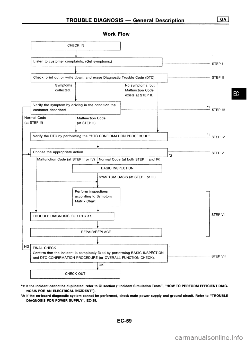
Work Flow
CHECK IN
Listen tocustomer complaints. (Getsymptoms.)
................................................STEPI
Check, printoutorwrite down, anderase Diagnostic TroubleCode(DTC).
Symptoms
collected. No
symptoms, but
Malfunction Code
exists atSTEP II. ..
STEPII
•
Verify
thesymptom bydriving inthe conditiOn the
customer described. *1
......................................................................................... STEPIII
Normal Code
(at STEP II) Malfunction
Code
(at STEP II)
Verify theDTC byperforming the"DTC CONFIRMATION PROCEDURE".
Choose theappropriate action.
Malfunction Code(atSTEP IIor IV) Normal Code(atboth STEP IIand IV)
BASIC INSPECTION
SYMPTOM BASIS(atSTEP Ior III)
Perform inspections
according toSymptom
Matrix Chart. *1
.. STEPIV
. STEPV
*2
TROUBLE DIAGNOSIS FORDTCXX. STEP
VI
REPAIR/REPLACE
NG FINAL CHECK
Confirm thattheincident iscompletely fixedbyperforming BASICINSPECTION
and DTC CONFIRMATION PROCEDURE(orOVERALL FUNCTION CHECK). ..........................................
STEPVII
CHECK OUT
*1: Ifthe incident cannotbeduplicated, refertoGI section ("Incident Simulation Tests","HOWTOPERFORM EFFICIENT DIAG-
NOSIS FORANELECTRICAL INCIDENT").
*2: Ifthe on-board diagnostic systemcannotbeperformed, checkmainpower supply andground circuit.Referto"TROUBLE
DIAGNOSIS FORPOWER SUPPLY", EC-88.
EC-59