1995 NISSAN ALMERA N15 low oil pressure
[x] Cancel search: low oil pressurePage 743 of 1701
ENGINEANDEMISSION BASICCONTROL SYSTEMDESCRIPTION
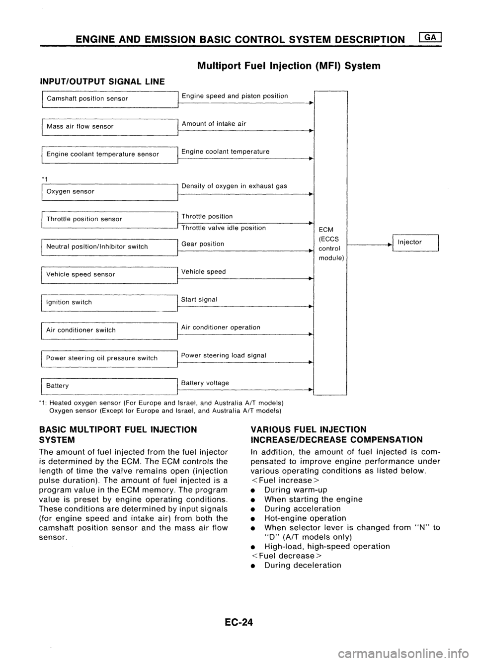
Multipart FuelInjection (MFI)System
INPUT/OUTPUT SIGNALLINE
Camshaft positionsensor
Mass airflow sensor
Engine coolant temperature sensor
*1
Oxygen sensor
Throttle position sensor
Neutral position/Inhibitor switch
Vehicle speedsensor
~gnition switch
Air conditioner switch
Power steering oilpressure switch
Battery Engine
speedandpiston position
Amount ofintake air
Engine coolant temperature
Density ofoxygen inexhaust gas
Throttle position
Throttle valveidleposition
Gear position
Vehicle speed
Start signal
Air conditioner operation
Power steering loadsignal
Battery voltage ECM
(ECCS
control module) Injector
*1: Heated oxygen sensor(ForEurope andIsrael, andAustralia A/Tmodels)
Oxygen sensor(Except forEurope andIsrael, andAustralia A/Tmodels)
BASIC MULTIPORT FUELINJECTION
SYSTEM
The amount offuel injected fromthefuel injector
is determined bythe ECM. TheECM controls the
length oftime thevalve remains open(injection
pulse duration). Theamount offuel injected isa
program valueinthe ECM memory. Theprogram
value ispreset byengine operating conditions.
These conditions aredetermined byinput signals
(for engine speedandintake air)from boththe
camshaft positionsensorandthemass airflow
sensor.
VARIOUS
FUELINJECTION
INCREASE/DECREASE COMPENSATION
In addition, theamount offuel injected iscom-
pensated toimprove engineperformance under
various operating conditions aslisted below.
<
Fuel increase>
• During warm-up
• When starting theengine
• During acceleration
• Hot-engine operation
• When selector leverischanged from"N"to
"D"
(AfT
models only)
• High-load, high-speed operation
<
Fuel decrease>
• During deceleration
EC-24
Page 754 of 1701

BASICSERVICE PROCEDURE
Idle Speedllgnition TiminglldleMixtureRatio
Adjustment
PREPARATION
• Make surethatthefollowing partsarein
good order.
(1) Battery
(2) Ignition system
(3) Engine oiland coolant levels
(4) Fuses
(5) ECM harness connector
(6) Vacuum hoses
(7) Airintake system
(Oil filler cap,oillevel gauge, etc.)
(8) Fuel pressure
(9)' Engine compression
(10) Throttle valve
(11) EGR valve operation -For Europe and
Israel andAustralia, andGA15DE M/Tmod-
els
Overall inspection sequence
INSPECTION
(12)
Evaporative emissionsystem
• On models equipped withairconditioner,
checks shouldbecarried outwhile theair
conditioner is"OFF".
• On models equipped withautomatic
transaxle, whenchecking idlespeed, ignition
timing andmixture ratio,checks shouldbe
carried outwhile shiftlever isin
"N"
position.
• When measuring
"CO"
percentage, insert
probe morethan40cm (15.7 in)into tailpipe .•
• Turn offheadlamps, heaterblower, rear
defogger.
• Keep frontwheels pointed straight ahead.
• Make thecheck afterthecooling fanhas
stopped.
Perform diagnostic testmode
1/
(Self-diagnostic results).
Check
&
adjust ignition timing.
Check
&
adjust idlespeed. NG
Repair orreplace.
Check oxygen sensor*1 function.
OK
Check
oxygen sensor*1 har-
ness.
Check CO%.
NG
NG
Repair orreplace harness.
OK Replace oxygensensor*1.
INSPECTION END Check
emission controlparts NGCheck oxygen sensor*1 function. OK
and repair orreplace ifneces-
sary.
*1: Heated oxygen sensor(ForEurope andIsrael, andAustralia AfTmodels)
Oxygen sensor(Except forEurope andIsrael, andAustralia AfTmodels)
EC-35
Page 768 of 1701
ON-BOARDDIAGNOSTIC SYSTEMDESCRIPTION
CONSULT (Cont'd)
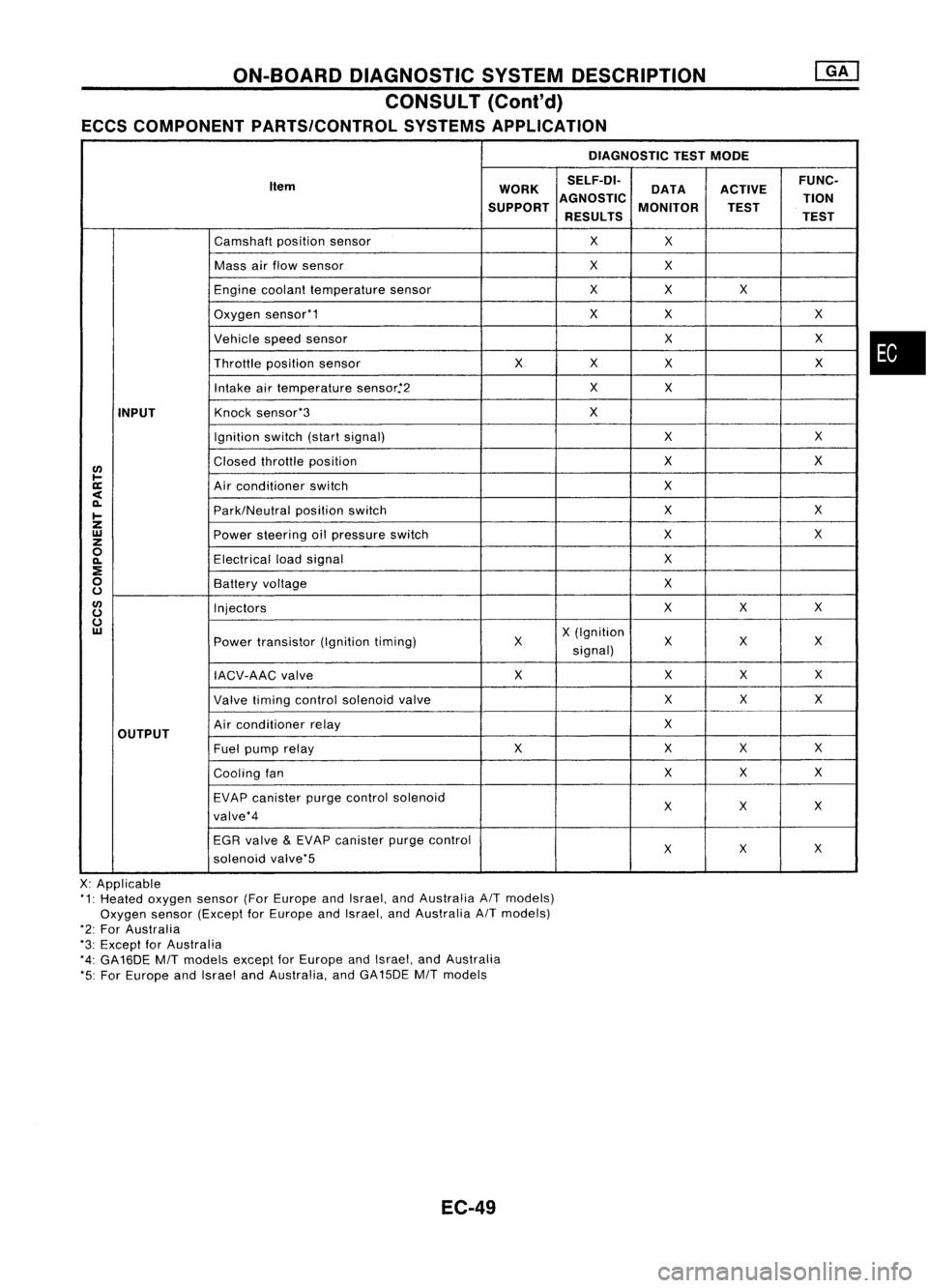
ECCS COMPONENT PARTS/CONTROL SYSTEMSAPPLICATION
DIAGNOSTICTESTMODE
Item WORKSELF-DI-
ACTIVEFUNC-
DATA
SUPPORT AGNOSTIC
MONITOR TION
TEST
RESULTS TEST
Camshaft positionsensor
X
X
Mass airflow sensor
X
X
Engine coolant temperature sensor
X
X X
Oxygen sensor'1
X
X X
Vehicle speedsensor
XX
Throttle positionsensor
XX
X X
Intake airtemperature sensor.'2
X
X
INPUT
Knock
sensor'3
X
Ignition switch(startsignal)
XX
I/)
Closed
throttle position
X
X
l-
ll:
Airconditioner switch
X
<
~
Park/Neutralpositionswitch
X
X
I-
Z
UJ
Powersteering oilpressure switch
XX
z
0
Electricalloadsignal
X
~
:E
0
Batteryvoltage
X
u
I/)
Injectors
XX
X
u
u
UJ
X(Ignition
Power transistor (Ignitiontiming) X X
XX
signal)
IACV-AAC valve X
XX
X
Valve timing control solenoid valve XX
X
OUTPUT
Air
conditioner relay
X
Fuel pump relay XX
XX
Cooling fan XX
X
EVAP canister purgecontrol solenoid
XX X
valve'4
EGR valve
&
EVAP canister purgecontrol
XX
X
solenoid valve'5
X: Applicable
'1: Heated oxygen sensor(ForEurope andIsrael, andAustralia AITmodels)
Oxygen sensor(Except forEurope andIsrael, andAustralia AITmodels)
'2: For Australia
'3: Except forAustralia
'4: GA16DE
MIT
models exceptforEurope andIsrael, andAustralia
'5: For Europe andIsrael andAustralia, andGA15DE
MIT
models
EC-49
•
Page 770 of 1701
ON-BOARDDIAGNOSTIC SYSTEMDESCRIPTION
CONSULT (ConI'd)
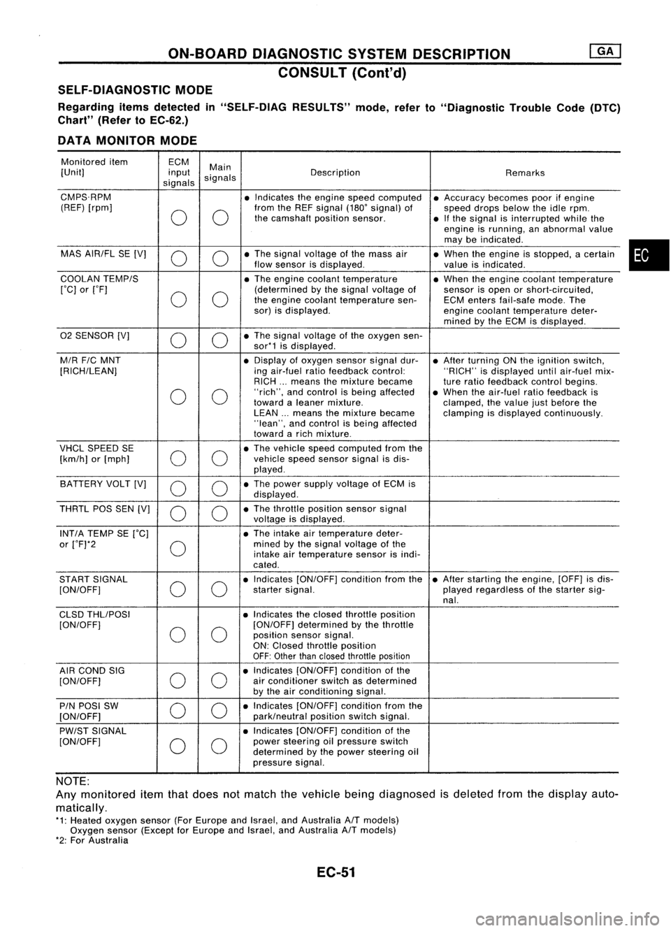
SELF-DIAGNOSTIC MODE
Regarding itemsdetected in"SELF-DIAG RESULTS"mode,referto"Diagnostic TroubleCode(DTC)
Chart" (RefertoEC-62.)
DATA MONITOR MODE
Monitored item ECM
Main
[Unit] input
signals Description
Remarks
signals
CMPS.RPM •Indicates theengine speedcomputed •Accuracy becomespoorifengine
(REF) [rpm]
00
from
theREF signal (180'signal) of
speeddropsbelow theidle rpm.
the camshaft positionsensor.
•Ifthe signal isinterrupted whilethe
engine isrunning, anabnormal value
may beindicated .
MAS AIR/FL SE[V]
0 0
•
The signal voltage ofthe mass air
•When theengine isstopped, acertain
flow sensor isdisplayed .
valueisindicated.
COOLAN TEMP/S
•The engine coolant temperature •When theengine coolant temperature
['C] or['F]
00
(determined
bythe signal voltage of
sensorisopen orshort-circuited,
the engine coolant temperature sen-ECMenters fail-safe mode.The
sor) isdisplayed.
enginecoolant temperature deter-
mined bythe ECM isdisplayed .
02 SENSOR [V]
00
•
The signal voltage ofthe oxygen sen-
sor*1 isdisplayed .
M/R F/CMNT •
Display ofoxygen sensorsignaldur-
•After turning ONthe ignition switch,
[RICH/LEAN] ingair-fuel ratiofeedback control: "RICH"isdisplayed untilair-fuel mix-
RICH ...means themixture became
tureratio feedback controlbegins.
0 0
"rich",
andcontrol isbeing affected •When theair-fuel ratiofeedback is
toward aleaner mixture.
clamped,thevalue justbefore the
LEAN ...means themixture became clampingisdisplayed continuously.
"lean", andcontrol isbeing affected
toward arich mixture .
VHCL SPEED SE
00
•
The vehicle speedcomputed fromthe
[km/h] or[mph] vehicle
speedsensor signalisdis-
played .
BATTERY VOLT[V]
0 0
•
The power supply voltage ofECM is
displayed .
THRTL POSSEN[V]
0 0
•
The throttle position sensorsignal
voltage isdisplayed.
INT/A TEMP SE['C] •The intake airtemperature deter-
or ['F]*2
0
mined
bythe signal voltage ofthe
intake airtemperature sensorisindi-
cated .
START SIGNAL
00
•
Indicates [ON/OFF] conditionfromthe•After starting theengine, [OFF]isdis-
[ON/OFF] startersignal. playedregardless ofthe starter sig-
nal.
CLSD THLIPOSI •Indicates theclosed throttle position
[ON/OFF]
00
[ON/OFF]
determined bythe throttle
position sensorsignal.
ON: Closed throttle position
OFF: Other thanclosed throttle position
AIR COND SIG
00
•
Indicates [ON/OFF] conditionofthe
[ON/OFF] air
conditioner switchasdetermined
by the airconditioning signal.
PIN POSI SW
00
•
Indicates [ON/OFF] conditionfromthe
[ON/OFF] park/neutralpositionswitchsignal.
PW/ST SIGNAL •
Indicates [ON/OFF] conditionofthe
[ON/OFF]
00
power
steering oilpressure switch
determined bythe power steering oil
pressure signal.
NOTE:
Any monitored itemthatdoes notmatch thevehicle beingdiagnosed isdeleted fromthedisplay auto-
matically.
*1: Heated oxygen sensor(ForEurope andIsrael, andAustralia A/Tmodels)
Oxygen sensor(Except forEurope andIsrael, andAustralia A/Tmodels)
*2: For Australia
EC-51
•
Page 774 of 1701
ON-BOARDDIAGNOSTIC SYSTEMDESCRIPTION
CONSULT (Conl'd)
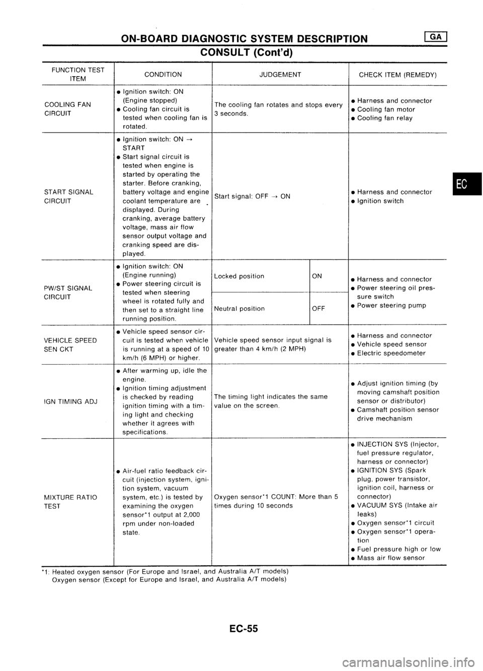
FUNCTION TEST
CONDITION JUDGEMENT
ITEM CHECK
ITEM(REMEDY)
• Ignition switch:ON
COOLING FAN (Engine
stopped)
Thecooling fanrotates andstops every •
Harness andconnector
CIRCUIT •
Cooling fancircuit is
3seconds. •
Cooling fanmotor
tested whencooling fanis
•Cooling fanrelay
rotated .
• Ignition switch:ON-.
START
• Start signal circuit is
tested whenengine is
started byoperating the
starter. Beforecranking,
START SIGNAL batteryvoltage andengine
Startsignal: OFF-.ON •
Harness andconnector
CIRCUIT coolanttemperature are •
Ignition switch
displayed. During
cranking, averagebattery
voltage, massairflow
sensor outputvoltage and
cranking speedaredis-
played .
• Ignition switch:ON
(Engine running)
Lockedposition ON
•Harness andconnector
PW/ST SIGNAL •
Power steering circuitis
•Power steering oilpres-
tested whensteering
CIRCUIT wheelisrotated fullyand sure
switch
then settoastraight lineNeutral
position OFF•
Power steering pump
running position.
• Vehicle speedsensor cir-
•Harness andconnector
VEHICLE SPEED cuit
istested whenvehicle Vehicle
speedsensor inputsignal is
•Vehicle speedsensor
SEN CKT is
running ataspeed of10 greater
than4km/h (2MPH)
•Electric speedometer
km/h (6MPH) orhigher .
• After warming up,idle the
engine. •Adjust ignition timing(by
• Ignition timingadjustment
movingcamshaft position
IGN TIMING ADJ is
checked byreading The
timing lightindicates thesame
sensorordistributor)
ignition timingwithatim- value
onthe screen.
•Camshaft positionsensor
ing light andchecking
drivemechanism
whether itagrees with
specifications.
•INJECTION SYS(Injector,
fuel pressure regulator,
harness orconnector)
• Air-fuel ratiofeedback cir- •
IGNITION SYS(Spark
cuit (injection system,igni- plug,
power transistor,
tion system, vacuum ignition
coil,harness or
MIXTURE RATIO system,
etc.)istested byOxygen
sensor'1 COUNT:Morethan5 connector)
TEST examining
theoxygen times
during 10seconds •
VACUUM SYS(Intake air
sensor'1 outputat2,000 leaks)
rpm under non-loaded •
Oxygen sensor'1 circuit
state. •
Oxygen sensor'1 opera-
tion
• Fuel pressure highorlow
• Mass airflow sensor
'1: Heated oxygen sensor(ForEurope andIsrael, andAustralia AITmodels)
Oxygen sensor(Except forEurope andIsrael, andAustralia
A/T
models)
EC-55
•
Page 791 of 1701
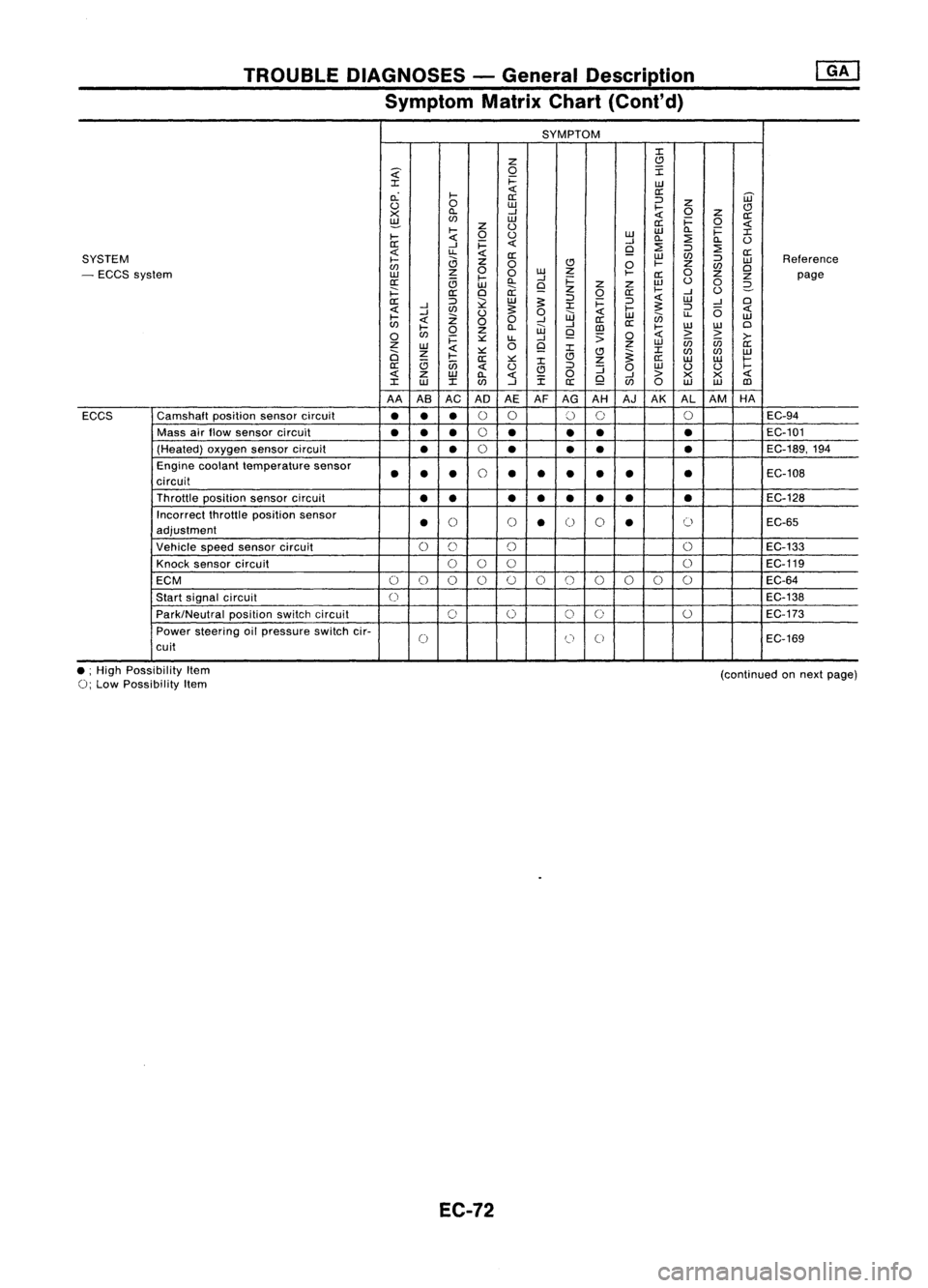
TROUBLEDIAGNOSES -General Description
Symptom MatrixChart(Cont'd)
SYMPTOM
:I:
Z
C)
~
0
I
:I:
i=
UJ
c.:
I-
«
a:
[ij'
a:
:J
u
0
UJ
I-
Z
C)
X
ll.
--l
«
0
z
a:
~
(f)
UJ
a:i=
0
«
I-
z
U
UJ
ll.
i=
:I:
I-
«
0
u
UJ
ll.
:2
ll.
U
a:
--l
i=
«
--l
:2
9
:J
:2
«
u.
«
a:
UJ
(f)
a:
SYSTEM
I-
a
z
:J
UJ
Reference
(f)
0
C)
0
I-
Z
(f)
Cl
- ECCS system
UJ
z
0
0
w
Z
I-
a:
0
z
z
page
a:
c;
l-
ll.
--l
i=
w
u
0
UJ
9
z
z
2-
i==:
a:
Cl
ii:
z
0
a:
I-
--l
U
a::
:J
l2
UJ
~
:J
i=
:J
«
UJ
--l
Cl
«
--l
(f)
~
:I:
I-
~
:J
(5
«
I-
--l
Z
U
0
UJ
«
UJ
en
u.
UJ
«
00
--l
a::
(f)
l-
ll.
W
--l
[])
a::
I-
w
W
Cl
0
(f)
0
z
9
;;
0
«
>
>
>-
i=
::.::
u.
--l
Z
0
9
z
UJ
in in
a::
UJ
«
:I:
:I:
a
z
I-
::.::
C)C)
~
(f)
(f)
UJ
a::
::.::
:I:
z
a::
UJ UJ
I-
a::
c;
in
«
u
C)
:J
:J
0
UJ
U U
I-
«
z
UJ
ll.
«
i
0
9
--l
>
X X
«
:I:
w
:I:(f)
--l
a::
(f)
0
UJ UJ
[])
AA ASAC AD AEAFAG AH AJAK ALAM HA
ECCS Camshaft
positionsensorcircuit
•••
0
0
()
0 0
EC-94
Mass airflow sensor circuit
••
•
0
•
••
•
EC-101
(Heated) oxygensensorcircuit
••
0
• •
•
•
EC-189,194
Engine coolant temperature sensor
••
•
0
••
•
•
•
•
EC-108
circuit
Throttle position sensorcircuit
•• ••• ••
•
EC-128
Incorrect throttleposition sensor
•
()
()
•
0
0
•
()
EC-65
adjustment
Vehicle speedsensor circuit
0
C)
()
0
EC-133
Knock sensor circuit
000 0
EC-119
ECM
0
()
0 0
()
0
()
()()
0 0
EC-64
Start signal circuit
0
EC-138
Park/Neutral positionswitchcircuit
0
0
0
0
0
EC-173
Power steering oilpressure switchcir-
0
(J
0
EC-169
cuit
• ;High Possibility Item
0;
Low Possibility Item
EC-72
(continued
onnext page)
Page 869 of 1701
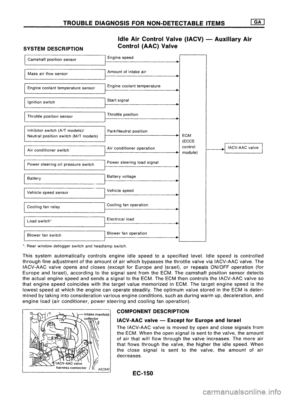
TROUBLEDIAGNOSIS FORNON-DETECTABLE ITEMS
SYSTEM DESCRIPTION Idle
AirControl Valve(IACV) -Auxiliary Air
Control (AAC)Valve
Camshaft positionsensor Engine
speed
I
Mass
airflow sensor Amount
ofintake air
I
Engine coolant temperature sensor Engine
coolant temperature
~
I
Ignition switch Start
signal
I
Throttle positionsensor Throttle
position
~
I
Inhibitor switch(A/Tmodels)/
Park/Neutralposition
Neutral position switch(M/Tmodels) ECM
(ECCS
Air conditioner operation control
!
IACV-AAC valve
I
Air conditioner switch
module)
Power steering oilpressure switch Power
steering loadsignal
I
Battery
~
Battery voltage
Vehicle speedsensor Vehicle
speed
Cooling fanrelay Cooling
fanoperation
Load switch' Electrical
load
Blower fanswitch Blower
fanoperation
': Rear window defogger switchandheadlamp switch.
This system automatically controlsengineidlespeed toaspecified level.Idlespeed iscontrolled
through fineadjustment ofthe amount ofair which bypasses thethrottle valveviaIACV-AAC valve.The
IACV-AAC valveopens andcloses (except forEurope andIsrael), orrepeats ON/OFF operation (for
Europe andIsrael), according tothe signal sentfrom theECM. Thecamshaft positionsensordetects
the actual engine speedandsends asignal tothe ECM. TheECM thencontrols theIACV-AAC valveso
that engine speedcoincides withthetarget valuememorized inECM. Thetarget engine speedisthe
lowest speedatwhich theengine canoperate steadily. Theoptimum valuestored inthe ECM isdeter-
mined bytaking intoconsideration variousengineconditions, suchasduring warmup,deceleration, and
engine load(airconditioner, powersteering andcooling fanoperation).
COMPONENT DESCRIPTION
IACV-AAC valve-Except forEurope andIsrael
The IACV-AAC valveismoved byopen andclose signals from
the ECM. When theopen signal issent tothe valve, theamount
of air that willflow through thevalve increases. Themore air
that flows through thevalve, thehigher theidle speed. When
the close signal issent tothe valve. theamount ofair
decreases.
EC-150
Page 891 of 1701
![NISSAN ALMERA N15 1995 Service Manual TROUBLEDIAGNOSIS FORNON-DETECTABLE ITEMS
@K]
Power Steering OilPressure Switch(Cont'd)
@:
ForAustralia
@:
Except forAustralia SEF176R
Repair
harness orcon-
nectors.
CHECK INPUTSIGNAL CIRCUIT. NISSAN ALMERA N15 1995 Service Manual TROUBLEDIAGNOSIS FORNON-DETECTABLE ITEMS
@K]
Power Steering OilPressure Switch(Cont'd)
@:
ForAustralia
@:
Except forAustralia SEF176R
Repair
harness orcon-
nectors.
CHECK INPUTSIGNAL CIRCUIT.](/manual-img/5/57349/w960_57349-890.png)
TROUBLEDIAGNOSIS FORNON-DETECTABLE ITEMS
@K]
Power Steering OilPressure Switch(Cont'd)
@:
ForAustralia
@:
Except forAustralia SEF176R
Repair
harness orcon-
nectors.
CHECK INPUTSIGNAL CIRCUIT. NG
Check thefollowing .
1. Disconnect ECMharness connector.
......---..
•Harness connectors
2. Check harness continuity between
aD,
(MID
ECM terminal
@
or
@
and terminal •
Harness connectors
G).
@,@or@,
Continuity shouldexist.
If
OK, check harness forshort. •
Harness foropen or
OK short
between ECMand
power steering oilpres-
sure switch
If NG, repair harness or
connectors.
CHECK COMPONENT NG
Replace powersteering
(Power steering oilpressure switch).
--...
oilpressure switch.
Refer to"COMPONENT INSPECTION"
below.
OK
Disconnect andreconnect harnesscon-
nectors inthe circuit. Thenretest.
Trouble isnot fixed.
Check ECMpinterminals fordamage or
the connection ofECM harness connec-
tor. Reconnect ECMharness connector
and retest.
@
1
CHECK GROUND CIRCUIT.
1. Turn ignition switch"OFF".
2. Disconnect powersteering oilpres-
sure switch harness connector.
3. Check harness continuity between
terminal
@
and engine ground.
Continuity shouldexist.
AEC760
IfOK, check harness forshort.
~i5
[i
c:ITb
~i5
ECM
Ef
CONNECTOR
II
43 25
II
INSPECTIONEND
Power steering oilpressure switch
1. Disconnect powersteering oilpressure switchharness con-
nector thenstart engine.
2. Check continuity betweenterminals
@.
[At
IV
ID
~ COMPONENT
INSPECTION
Conditions
Steering wheelisbeing turned
Steering wheelisnot being turned Continuity
Yes
No
AEC762
IfNG, replace powersteering oilpressure switch.
EC-172