1995 NISSAN ALMERA N15 low oil pressure
[x] Cancel search: low oil pressurePage 1359 of 1701
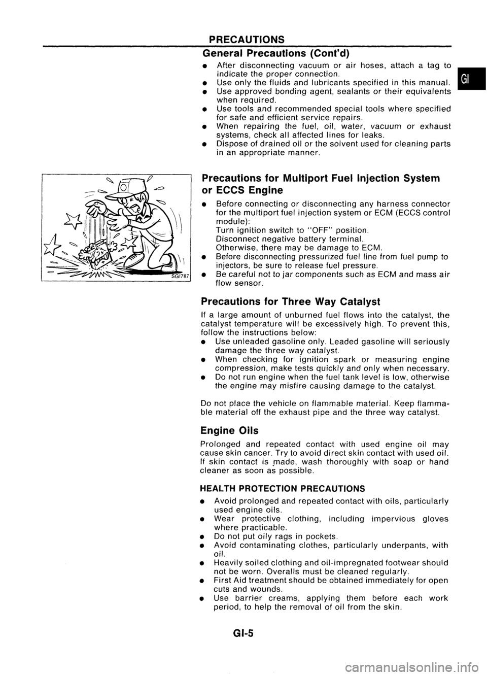
PRECAUTIONS
General Precautions (Cont'd)
• After disconnecting vacuumorair hoses, attachatag to
indicate theproper connection.
• Use only thefluids andlubricants specifiedinthis manual.
• Use approved bondingagent,sealants ortheir equivalents
when required.
• Use tools andrecommended specialtoolswhere specified
for safe andefficient servicerepairs.
• When repairing thefuel, oil,water, vacuum orexhaust
systems, checkallaffected linesforleaks.
• Dispose ofdrained oilorthe solvent usedforcleaning parts
in an appropriate manner.
Precautions forMultiport FuelInjection System
or ECCS Engine
• Before connecting ordisconnecting anyharness connector
for the multiport fuelinjection systemorEGM (EGGS control
module):
Turn ignition switchto"OFF" position.
Disconnect negativebatteryterminal.
Otherwise, theremaybedamage toEGM.
• Before disconnecting pressurizedfuellinefrom fuelpump to
injectors, besure torelease fuelpressure.
• Becareful nottojar components suchasEGM andmass air
flow sensor.
Precautions forThree WayCatalyst
If a large amount ofunburned fuelflows intothecatalyst, the
catalyst temperature willbeexcessively high.Toprevent this,
follow theinstructions below:
• Use unleaded gasolineonly.Leaded gasoline willseriously
damage thethree waycatalyst.
• When checking forignition sparkormeasuring engine
compression, maketestsquickly andonly when necessary.
• Donot run engine whenthefuel tank level islow, otherwise
the engine maymisfire causing damage tothe catalyst.
Do not place thevehicle onflammable material.Keepflamma-
ble material offthe exhaust pipeandthethree waycatalyst.
Engine Oils
Prolonged andrepeated contactwithused engine oilmay
cause skincancer. Trytoavoid direct skincontact withused oil.
If skin contact is.made, washthoroughly withsoap orhand
cleaner assoon aspossible.
HEALTH PROTECTION PRECAUTIONS
• Avoid prolonged andrepeated contactwithoils, particularly
used engine oils.
• Wear protective clothing,including impervious gloves
where practicable.
• Donot putoily rags inpockets.
• Avoid contaminating clothes,particularly underpants, with
oil.
• Heavily soiledclothing andoil-impregnated footwearshould
not beworn. Overalls mustbecleaned regularly.
• First Aidtreatment shouldbeobtained immediately foropen
cuts andwounds.
• Use barrier creams, applying thembefore eachwork
period, tohelp theremoval ofoil from theskin.
GI-5
•
Page 1371 of 1701
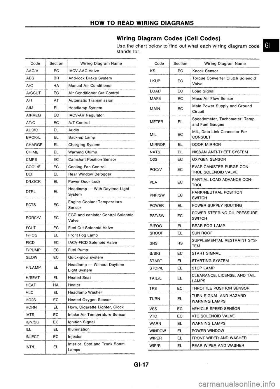
HOWTOREAD WIRING DIAGRAMS
Wiring Diagram Codes(CellCodes)
Use thechart below to'find outwhat each wiring diagram code•
stands for,
Code Section WiringDiagram Name
AACIV ECIACV-AAC
Valve
ABS BR
Anti-lock BrakeSystem
A/C HAManualAirConditioner
A/CCUT ECAir
Conditioner CutControl
A/T ATAutomatic Transmission
AIM ELHeadlamp System
AIRREG ECIACV-Air Regulator
AT/C ECA/TControl
AUDIO ELAudio
BACK/L ELBack-up Lamp
CHARGE ELCharging System
CHIME ELWarning Chime
CMPS EC
Camshaft PositionSensor
COOllF ECCooling
FanControl
DEF ELRearWindow Defogger
D/LOCK ELPowerDoorLock
DTRL ELHeadlamp
-With Daytime Light
System
ECTS ECEngine
Coolant Temperature
Sensor
EGR andcanister ControlSolenoid
EGRCIV EC
Valve
FCUT ECFuel
CutSolenoid Valve
F/FOG ELFront
FogLamp
FICO ECIACV-FICD
SolenoidValve
F/PUMP ECFuel
Pump
GLOW ECQuick-glow
system
H/LAMP ELHeadlamp
-Without Daytime
Light System
H/SEAT ELHeated
Seat
HEAT HA
Heater
HLC ELHeadlamp
Washer
H02S ECHeated
Oxygen Sensor
HORN ELHorn,
Cigarette Lighter,Clock
IATS ECIntake
AirTemperature Sensor
IGN/SG ECIgnition
Signal
ILL ELIllumination
INJECT ECInjector
INT/L ELInterior,
SpotandTrunk Room
Lamps Code
Section WiringDiagram Name
KS ECKnock
Sensor
LKUP ECTorque
Converter ClutchSolenoid
Valve
LOAD ECLoadSignal
MAFS ECMass
AirFlow Sensor
MAIN ECMain
Power Supply andGround
Circuit
METER ELSpeedometer,
Tachometer,Temp.
and Fuel Gauges
MIL ECMIL,
Data LinkConnector For
CONSULT
MIRROR ELDOOR
MIRROR
NATS ELNISSAN
ANTI-THEFT SYSTEM
02S ECOXYGEN
SENSOR
EC EVAP
CANISTER PURGECON-
PGCIV TROLSOLENOID VALVE
PLA ECPARTIAL
LOADADVANCE CON-
TROL
EC PARK/NEUTRAL
POSITION
PNP/SW SWITCH
POWER ELPOWER
SUPPLY ROUTING
POWER STEERING OILPRESSURE
PST/SW EC
SWITCH
R/FOG ELREAR
FOGLAMP
SROOF ELSUN
ROOF
SUPPLEMENTAL RESTRAINTSYS-
SRS RS
TEM
S/SIG ECST
ART SIGNAL
START ELSTARTING
SYSTEM
STOP/L ELSTOP
LAMP
TAllIL ELCLEARANCE,
LICENSE,ANDTAIL
LAMPS
TPS ECTHROTTLE
POSITIONSENSOR
TURN SIGNAL ANDHAZARD
TURN EL
WARNING LAMPS
VSS ECVEHICLE
SPEEDSENSOR
VTC ECVTC
SOLENOID VALVE
WARN ELWARNING
LAMPS
WINDOW ELPOWER
WINDOW
WIPER ELFRONT
WIPERANDWASHER
WIP/R ELREAR
WIPER ANDWASHER
GI-17
Page 1406 of 1701
PRECAUTIONSANDPREPARATION
Precautions forRefrigerant Connection
WARNING: Make sureallrefrigerant isdischarged intotherecycling equipment andthepressure inthe system is
less than atmospheric pressure.Thengradually loosenthedischarge sidehose fitting andremove it.
CAUTION:
When replacing orcleaning refrigerant cyclecomponents, observethefollowing.
• When thecompressor isremoved, storeitin the same position asitis when mounted onthe car.
Failure todo sowill cause lubricant toenter thelow pressure chamber.
• When connecting tubes,always useatorque wrench andaback-up wrench.
• After disconnecting tubes,immediately plugallopenings toprevent entryofdirt and moisture.
• When installing anair conditioner inthe vehicle, connect thepipes asthe final stage ofthe opera-
tion. Donot remove theseal caps ofpipes andother components untiljustbefore required forcon-
nection.
• Allow components storedincool areas towarm toworking areatemperature beforeremoving seal
caps. Thisprevents condensation fromforming inside
AIC
components.
• Thoroughly removemoisture fromtherefrigeration systembeforecharging therefrigerant.
• Always replace usedO-rings.
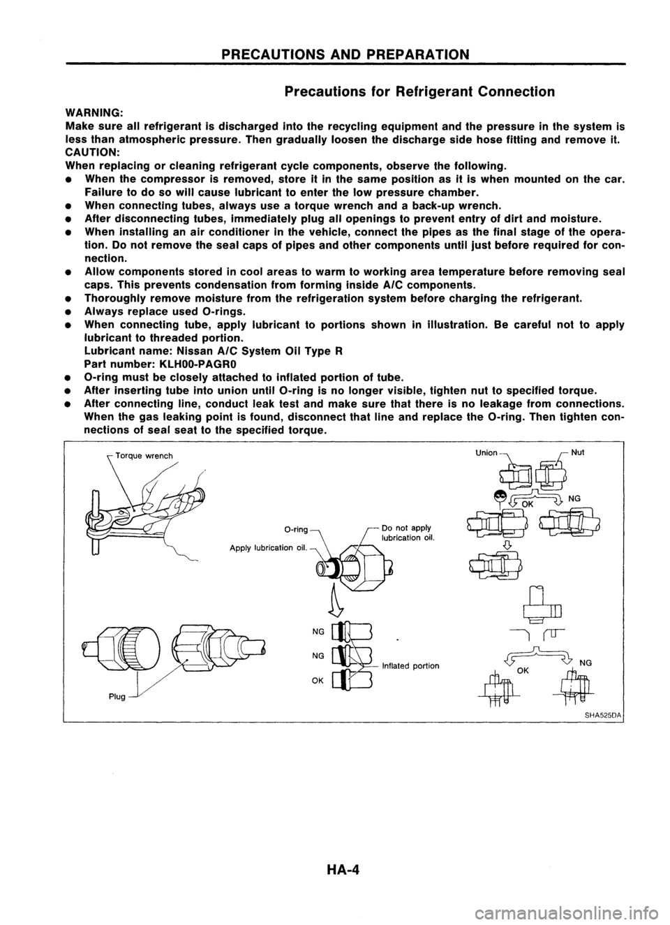
• When connecting tube,apply lubricant toportions showninillustration. Becareful nottoapply
lubricant tothreaded portion.
Lubricant name:Nissan
AIC
System OilType R
Part number: KLHOO-PAGRO
• O-ring mustbeclosely attached toinflated portionoftube.
• After inserting tubeintounion untilO-ring isno longer visible, tightennuttospecified torque.
• After connecting line,conduct leaktestand make surethatthere isno leakage fromconnections.
When thegas leaking pointisfound, disconnect thatlineand replace theO-ring. Thentighten con-
nections ofseal seattothe specified torque.
O-ring
Apply lubrication oil.
NG
NG
OK -
Inflated portion
SHA525DA
HA-4
Page 1410 of 1701
PRECAUTIONSANDPREPARATION
Precautions forService Equipment
RECOVERY/RECYCLING/RECHARGING EQUIPMENT
Be certain tofollow themanufacturers instructionsformachine
operation andmachine maintenance. Neverintroduce any
refrigerant otherthanthatspecified intothemachine.
ELECTRONIC LEAKDETECTOR
Be certain tofollow themanufactures instructionsfortester
operation andtester maintenance.
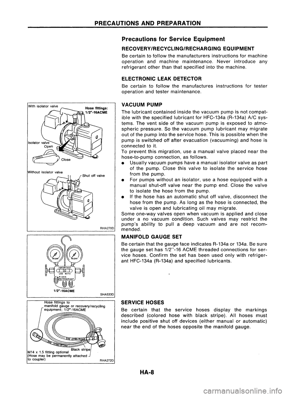
With isolator valve
Without isolatorvalve
VACUUM
PUMP
Hose fittings:
1/2".16ACME
Thelubricant contained insidethevacuum pumpisnot compat-
ible with thespecified lubricantforHFC-134a (R-134a)
AIC
sys-
tems. Thevent sideofthe vacuum pumpisexposed toatmo-
spheric pressure. Sothe vacuum pumplubricant maymigrate
out ofthe pump intotheservice hose.Thisispossible whenthe
pump isswitched offafter evacuation (vacuuming) andhose is
connected toit.
To prevent thismigration, useamanual valveplaced nearthe
hose-to-pump connection,asfollows.
• Usually vacuum pumpshaveamanual isolatorvalveaspart
of the pump. Closethisvalve toisolate theservice hose
from thepump.
• For pumps without anisolator, useahose equipped witha
manual shut-off valvenearthepump end.Close thevalve
to isolate thehose fromthepump.
• Ifthe hose hasanautomatic shutoffvalve, disconnect the
hose fromthepump. Aslong asthe hose isconnected, the
valve isopen andlubricating oilmay migrate.
Some one-way valvesopenwhen vacuum isapplied andclose
under ano vacuum condition. Suchvalves mayrestrict the
pump's abilitytopull adeep vacuum andarenotrecom-
RHA270D
mended.
MANIFOLD GAUGESET
Be certain thatthegauge faceindicates R-134aor134a. Besure
the gauge sethas
1/2"-16
ACMEthreaded connections forser-
vice hoses. Confirm theset has been usedonlywith refriger-
ant HFC-134a (R-134a)andspecified lubricants.
~
1f2"-16ACME
SHA533D
Hose fittings to
manifold gaugeorrecovery/recycling
equipment; 1/2"-16ACME
RHA272DSERVICE
HOSES
Be certain thattheservice hosesdisplay themarkings
described (coloredhosewithblack stripe). Allhoses must
include positive shutoffdevices (eithermanual orautomatic)
near theend ofthe hoses opposite themanifold gauge.
HA-8
Page 1412 of 1701
DESCRIPTION
Refrigeration Cycle
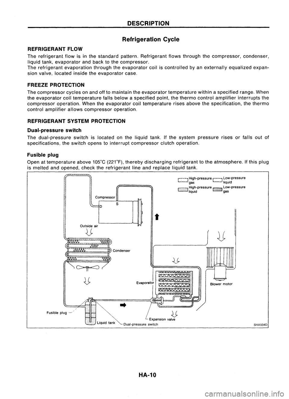
REFRIGERANT FLOW
The refrigerant flowisinthe standard pattern.Refrigerant flowsthrough thecompressor, condenser,
liquid tank,evaporator andback tothe compressor.
The refrigerant evaporation throughtheevaporator coiliscontrolled byan externally equalizedexpan-
sion valve, located insidetheevaporator case.
FREEZE PROTECTION
The compressor cyclesonand offtomaintain theevaporator temperature withinaspecified range.When
the evaporator coiltemperature fallsbelow aspecified point,thethermo controlamplifier interrupts the
compressor operation.Whentheevaporator coiltemperature risesabove thespecification, thethermo
control amplifier allowscompressor operation.
REFRIGERANT SYSTEMPROTECTION
Dual-pressure switch
The dual-pressure switchislocated onthe liquid tank.Ifthe system pressure risesorfalls outof
specifications, theswitch openstointerrupt compressor clutchoperation.
Fusible plug
Open attemperature above105°C(221°F), thereby discharging refrigeranttothe atmosphere. Ifthis plug
is melted andopened, checktherefrigerant lineand replace liquidtank.
c:::::.J
High-pressure
EJ
Low-pressure
gas liquid
1:-:-:-:-::-:-::-:-:1
~~~~pressure
!::i'i'i':}':J
~~:-pressure
Compressor
D
Outside air
U
s
t
Fusible plug-~
~..
U
'" Expansionvalve
Liquid tank"'--Dual-pressure switch
HA-10
Blower
motor
SHA504D
Page 1422 of 1701
TROUBLEDIAGNOSES
Preliminary Check
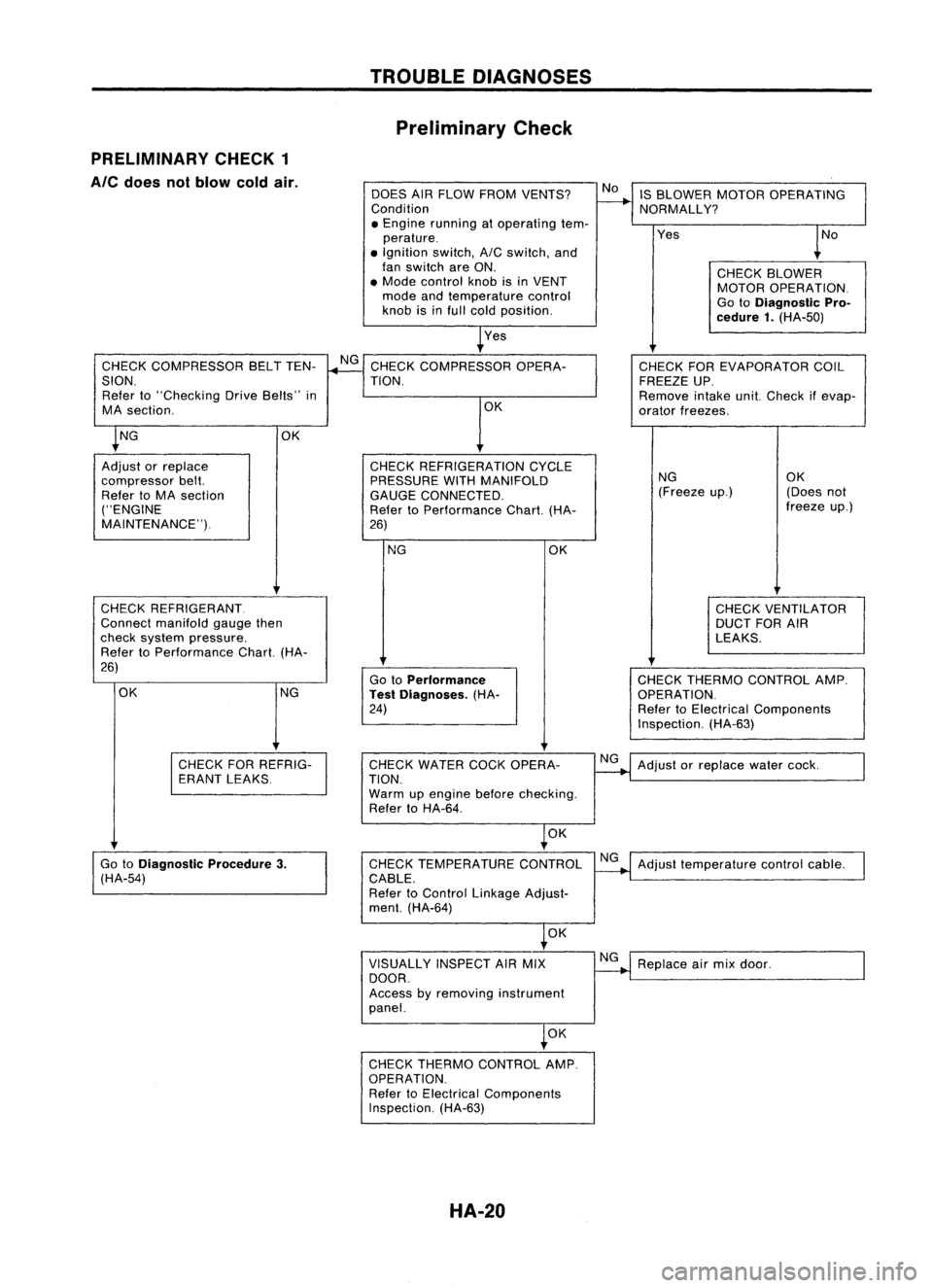
PRELIMINARY CHECK1
Ale
does notblow coldair.
DOESAIRFLOW FROM VENTS?
Condition
• Engine running atoperating tem-
perature .
• Ignition switch,AICswitch, and
fan switch areON.
• Mode control knobisin VENT
mode andtemperature control
knob isinfull cold position.
Yes IS
BLOWER MOTOROPERATING
NORMALLY?
Yes
CHECKBLOWER
MOTOR OPERATION.
Go toDiagnostic Pro-
cedure 1.(HA-50)
CHECK COMPRESSOR BELTTEN-
SION. Refer to"Checking DriveBelts" in
MA section.
CHECK REFRIGERANT.
Connect manifold gaugethen
check system pressure.
Refer toPerformance Chart.(HA-
26)
NG CHECK
THERMO CONTROL AMP.
OPERATION.
Refer toElectrical Components
Inspection. (HA-63)
CHECK
FOREVAPORATOR COIL
FREEZE UP.
Remove intakeunit.Check ifevap-
orator freezes.
NG OK
(Freeze up.) (Doesnot
freeze up.)
CHECK VENTILATOR
DUCT FORAIR
LEAKS.
OK
Go toPerformance
Test Diagnoses. (HA-
24)
NG
CHECK
REFRIGERATION CYCLE
PRESSURE WITHMANIFOLD
GAUGE CONNECTED.
Refer toPerformance Chart.(HA-
26) OK
CHECK
COMPRESSOR OPERA-
TION.
OK
OK NG
Adjust orreplace
compressor belt.
Refer toMA section
("ENGINE
MAINTENANCE").
CHECKFORREFRIG-
ERANT LEAKS CHECK
WATER COCKOPERA-
TION.
Warm upengine beforechecking.
Refer toHA-64.
NG
Adjust orreplace watercock.
OK
Go toDiagnostic Procedure3.
(HA-54) CHECK
TEMPERATURE CONTROL
CABLE.
Refer toControl Linkage Adjust-
ment. (HA-64) NG
Adjust temperature controlcable.
OK
VISUALLY INSPECTAIRMIX
DOOR.
Access byremoving instrument
panel. NG
Replace airmix door.
OK
CHECK THERMO CONTROL AMP.
OPERATION. Refer toElectrical Components
Inspection. (HA-63)
HA-20
Page 1427 of 1701
TROUBLEDIAGNOSES
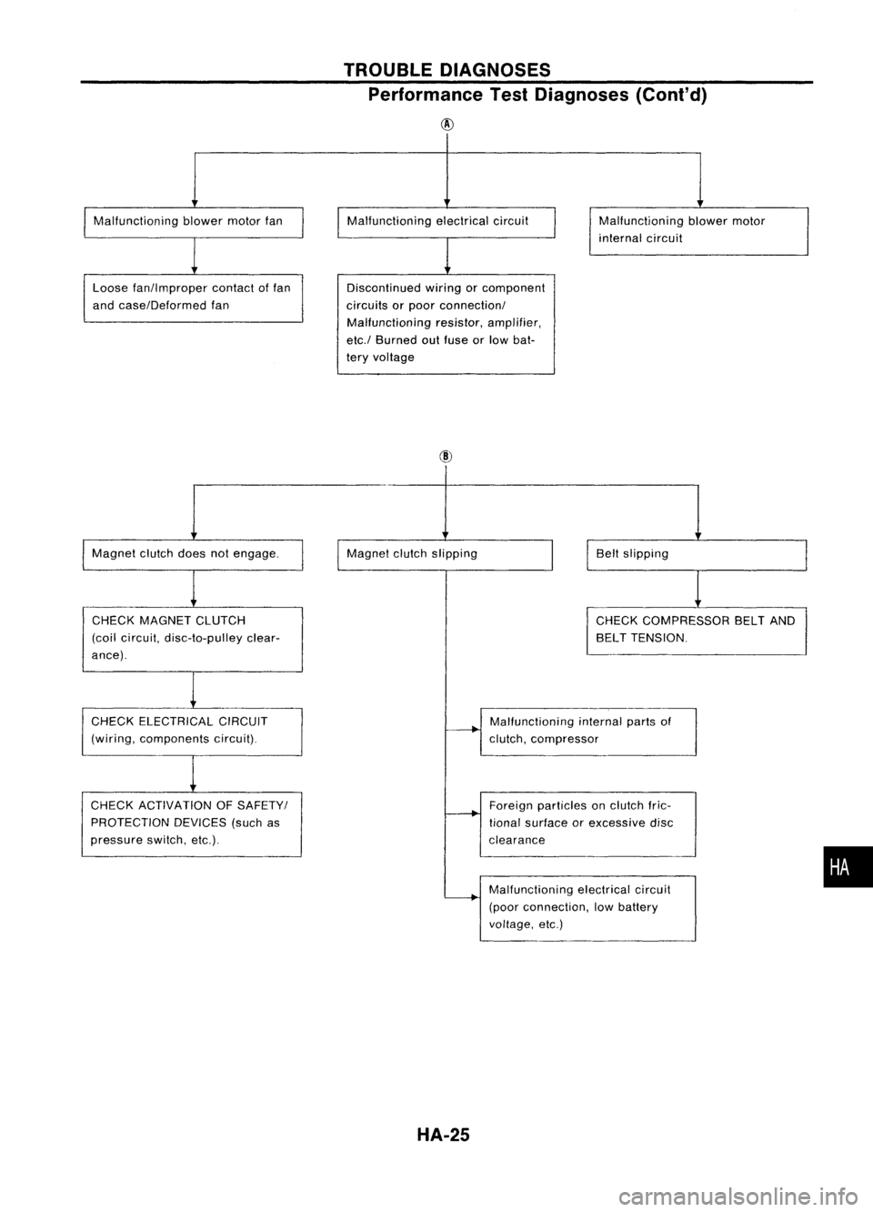
Performance TestDiagnoses (Cont'd)
@
Malfunctioning blowermotorfan
Loose fan!lmproper contactoffan
and case!Deformed fan Malfunctioning
electricalcircuit
Discontinued wiringorcomponent
circuits orpoor connection!
Malfunctioning resistor,amplifier,
etc.! Burned outfuse orlow bat-
tery voltage Malfunctioning
blowermotor
internal circuit
Magnet clutchdoesnotengage.
CHECK MAGNET CLUTCH
(coil circuit, disc-to-pulley clear-
ance). Magnet
clutchslipping
Beltslipping
CHECK COMPRESSOR BELTAND
BELT TENSION.
CHECK ELECTRICAL CIRCUIT
(wiring, components circuit).
CHECK ACTIVATION OFSAFETY!
PROTECTION DEVICES(suchas
pressure switch,etc.). Malfunctioning
internalpartsof
clutch, compressor
Foreign particles onclutch fric-
tional surface orexcessive disc
clearance
Malfunctioning electricalcircuit
(poor connection, lowbattery
voltage, etc.)
HA-25
•
Page 1470 of 1701
SERVICEPROCEDURES
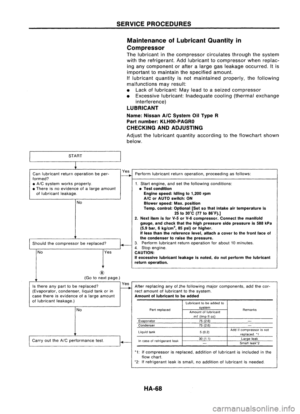
Maintenance ofLubricant Quantityin
Compressor
The lubricant inthe compressor circulatesthroughthesystem
with therefrigerant. Addlubricant tocompressor whenreplac-
ing any component orafter alarge gasleakage occurred. Itis
important tomaintain thespecified amount.
If lubricant quantityisnot maintained properly,thefollowing
malfunctions mayresult:
• Lack oflubricant: Maylead toaseized compressor
• Excessive lubricant:Inadequate cooling(thermal exchange
interference)
LUBRICANT
Name: Nissan
Ale
System OilType R
Part number:
KLHOO-PAGRO
CHECKING ANDADJUSTING
Adjust thelubricant quantityaccording tothe flowchart shown
below.
START
~
Can lubricant returnoperation beper- Yes
Perform lubricant returnoperation, proceeding asfollows:
formed?
-+
• AIC
system worksproperly. 1.Start engine, andsetthefollowing conditions:
• There isno evidence ofalarge amount •Test condition
of lubricant leakage. Engine
speed:Idlingto1,200 rpm
AlC orAUTO switch: ON
No Blowerspeed:Max.position
Temp. control: Optional [Setsothat Intake airtemperature is
25 to30°C (77to86°F).]
2. Next itemisfor V-5 orV-6 compressor. Connectthemanifold
gauge, andcheck thatthehigh pressure sidepressure is588 kPa
(5.9 bar, 6kg/cm
2,
85psi) orhigher,
If
less than thereference level,attach acover tothe front faceof
~
the
condenser toraise thepressure.
Should thecompressor bereplaced?
3.
Perform lubricant returnoperation forabout 10minutes.
4.
Stop engine.
No Yes
CAUTION:
If
excessive lubricantleakageisnoted, donot perform thelubricant
return operation.
@
(Go tonext page.)
Is there anypart tobe replaced? Yes
Afterreplacing anyof.the following majorcomponents, addthecor-
(Evaporator, condenser,liquidtankorin
-..
rectamount oflubricant tothe system.
case there isevidence ofalarge amount Amountoflubricant tobe added
of lubricant leakage.)
Lubricanttobe added to
No
Part
replaced system
Remarks
Amount oflubricant
mf (Imp IIoz)
Evaporator 75(2.6)
-
Condenser 75(2.6)
-
Liquid tank 5(0.2) Add
ifcompressor isnot
replaced. '1
Carry outthe
AIC
performance test.
~
In
case ofrefrigerant leak 30
(11) Largeleak
-
Small
leak'2
.
*1:Ifcompressor isreplaced. additionoflubricant isincluded inthe
flow chart.
*2: Ifrefrigerant leakissmall, noaddition oflubricant isneeded.
HA-68