Page 1178 of 1701
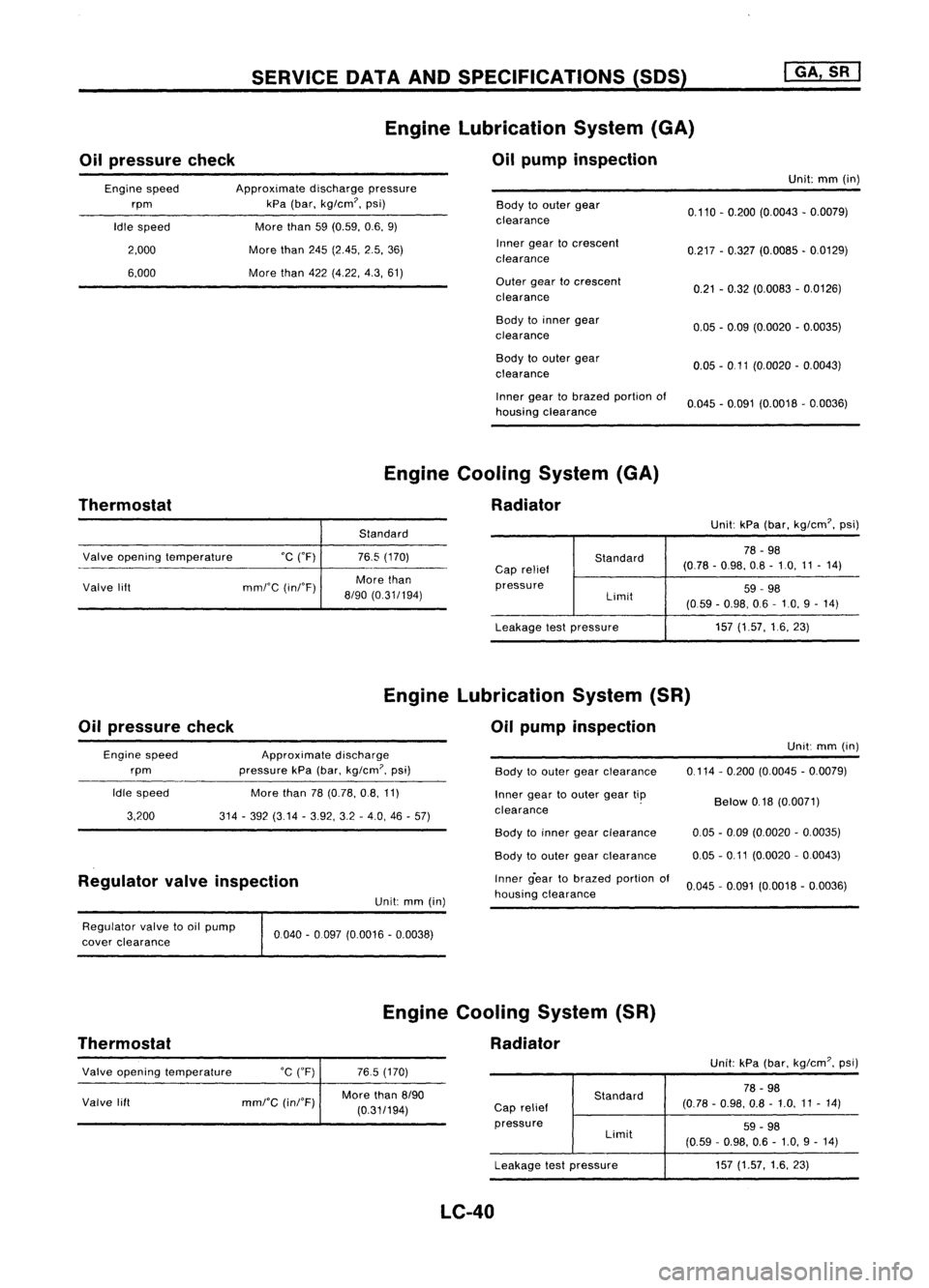
Oilpressure checkSERVICE
DATAANDSPECIFICATIONS (50S)
Engine Lubrication System(GA)
Oil pump inspection
I
GA, SR
I
Engine speed
rpm
Idle speed
2,000
6,000
Approximate
dischargepressure
kPa (bar, kg/cm?, psi)
More than
59(0.59, 0.6,9)
More than
245(2.45, 2.5,36)
More than
422(4,22, 4.3,61)
Body
toouter gear
clearance
Inner geartocrescent
clearance
Outer geartocrescent
clearance
Body toinner gear
clearance
Body toouter gear
clearance
Inner geartobrazed portionof
housing clearance Unit:
mm(in)
0.110 -0.200 (0.0043 -0.0079)
0.217 -0.327 (0.0085 -0.0129)
0.21 -0.32 (0.0083 -0.0126)
0.05 -0.09 (0.0020 -0.0035)
0.05 -0 11 (0.0020 -0.0043)
0.045 -0.091 (0.0018 -0.0036)
Thermostat Engine
Cooling System(GA)
Radiator
Standard Unit:
kPa(bar, kg/cm?, psi)
Valve opening temperature °C("F)
Valve lift mml'C(inI'F)
76.5
(170)
More than
8/90 (0.31/194)
Standard
Cap relief
pressure Limit
Leakage testpressure
78
-98
(0.78 -0.98, 0.8-10, 11-14)
59 -98
(059 -0.98, 06-10, 9-14)
157 (1.57, 16,23)
Oil pressure check Engine
Lubrication System(SR)
Oil pump inspection
Engine speed
rpm
Idle speed
3,200
Approximate
discharge
pressure kPa(bar,
kg/cm?,
psi)
More than
78(0.78, 0.8,11)
314 -392 (3.14 -3.92, 3.2-4.0, 46-57)
Body
toouter gearclearance
Inner geartoouter geartip
clearance . Unit:
mm(in)
0,114 -0,200 (0.0045 -0.0079)
Below
0.18(0.0071)
Regulator valveinspection
Unit:mm(in) Body
toinner gearclearance
Body toouter gearclearance
Inner g-eartobrazed portionof
housing clearance
0.05
-0.09 (0.0020 -0.0035)
0.05 -0.11 (0.0020 -0,0043)
0.045 -0,091 (0,0018 -0,0036)
Regulator valvetooil pump
cover clearance
Thermostat 0040
-0097 (0,0016 -0.0038)
Engine Cooling System(SR)
Radiator
Valve opening temperature
Valve lift
°C
(OF)
mml"C
(inI"F)
765
(170)
More than
8/90
(0,31/194)
Standard
Cap relief
pressure Limit
Leakage testpressure
LC-40
Unit:
kPa(bar, kg/em?, psi)
78 -98
(0.78 -0,98, 0.8-1,0, 11-14)
59 -98
(0,59 -0.98, 0.6-1.0, 9-14)
157 (1.57, 1.6,23)
Page 1194 of 1701
COMPRESSIONPRESSURE
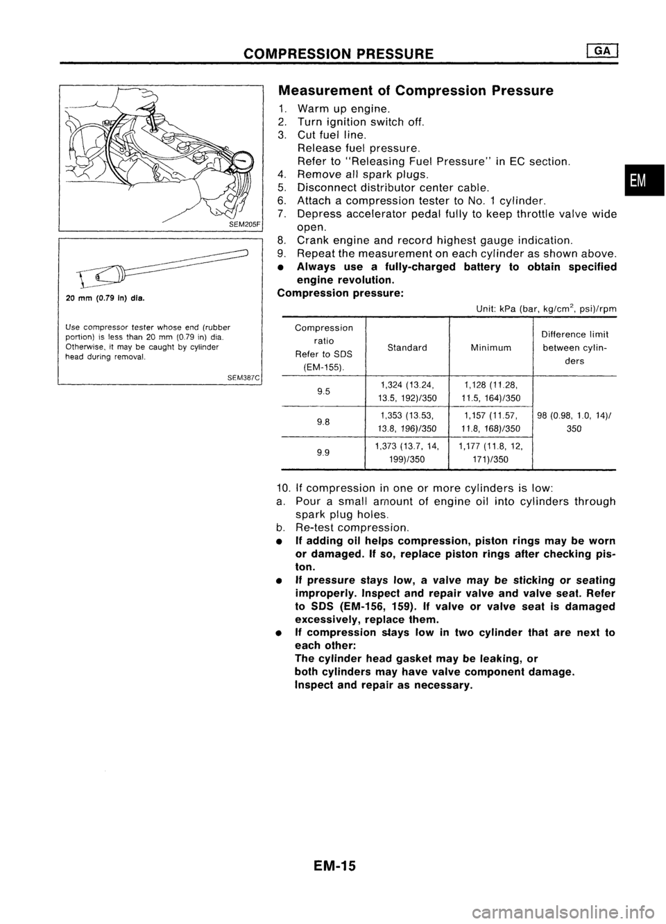
20
mm
(O.79 In)dls.
Use compressor testerwhose end(rubber
portion) isless than 20mm (0.79 in)dia.
Otherwise, itmay becaught bycylinder
head during removal.
SEM387CMeasurement
ofCompression Pressure
1. Warm upengine.
2. Turn ignition switchoff.
3. Cut fuel line.
Release fuelpressure.
Refer to"Releasing FuelPressure" inEC section. •
4. Remove allspark plugs.
5. Disconnect distributorcentercable.
6. Attach acompression testertoNO.1 cylinder.
7. Depress accelerator pedalfullytokeep throttle valvewide
open.
8. Crank engine andrecord highest gaugeindication.
9. Repeat themeasurement oneach cylinder asshown above.
• Always useafully-charged batterytoobtain specified
engine revolution.
Compression pressure:
Unit:kPa(bar, kg/cm
2,
psi)/rpm
Compression Differencelimit
ratio
Standard
Refer toSOS Minimum
betweencylin-
(EM-155). ders
9.5 1,324
(13.24, 1,128(11.28,
13.5, 192)/350 11.5,164)/350
9.8 1,353
(1353, 1,157(11.57, 98(0.98, 1.0,14)/
13.8, 196)/350 11.8,168)/350
350
9.9 1,373
(13.7, 14, 1,177(11.8,12,
199)/350 171)/350
10.
If
compression inone ormore cylinders islow:
a. Pour asmall amount ofengine oilinto cylinders through
spark plugholes.
b. Re-test compression,
• Ifadding oilhelps compression, pistonringsmaybeworn
or damaged. Ifso, replace pistonringsafterchecking pis-
ton.
• Ifpressure stayslow,avalve maybesticking orseating
improperly. Inspectandrepair valveandvalve seat.Refer
to SOS (EM-156, 159).Ifvalve orvalve seatisdamaged
excessively, replacethem.
• Ifcompression stayslowintwo cylinder thatarenext to
each other:
The cylinder headgasket maybeleaking, or
both cylinders mayhave valve component damage.
Inspect andrepair asnecessary.
EM-15
Page 1199 of 1701
TIMINGCHAIN
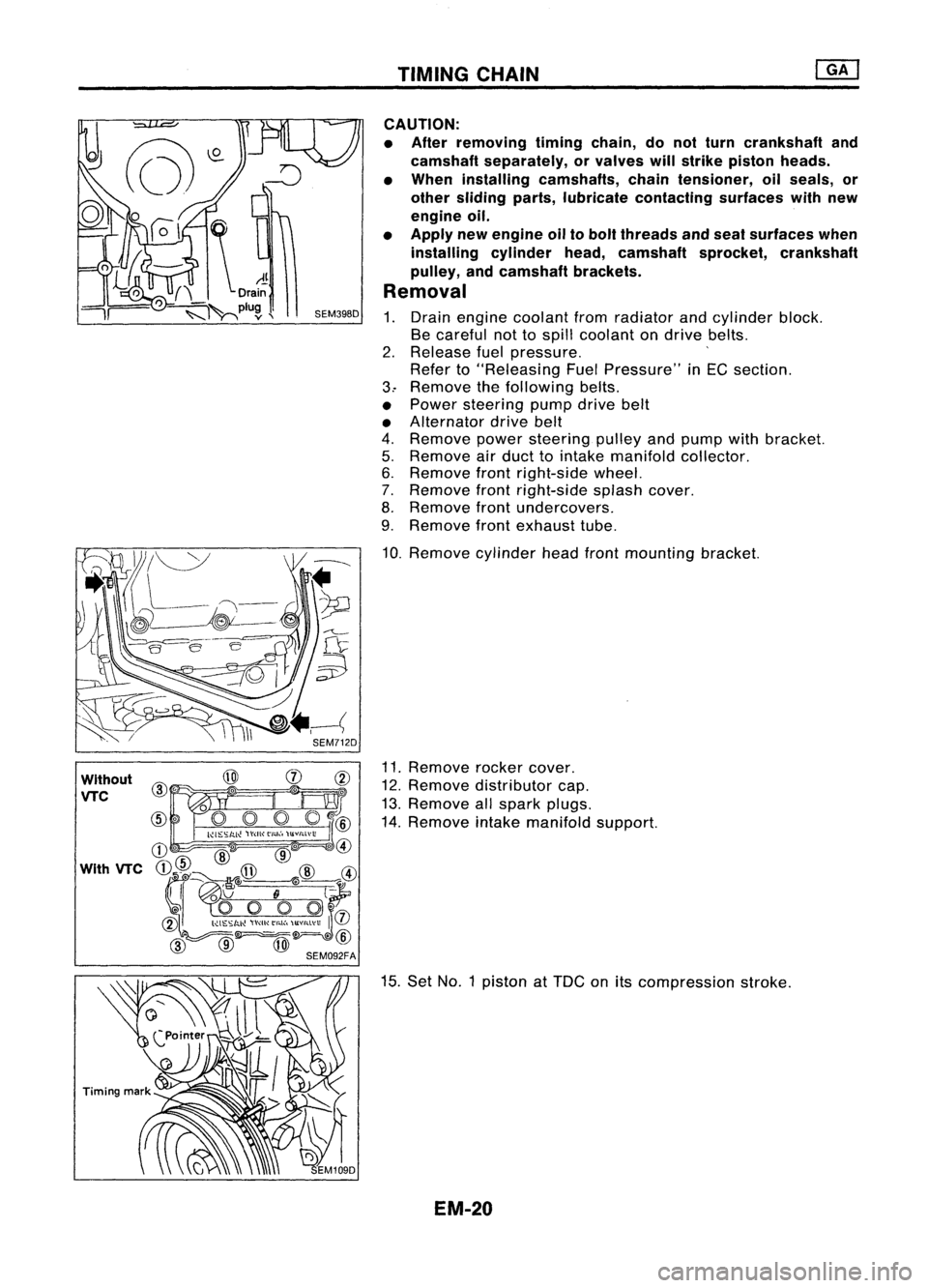
Without
VTC
CAUTION:
• After removing timingchain,donot turn crankshaft and
camshaft separately, orvalves willstrike piston heads.
• When installing camshafts, chaintensioner, oilseals, or
other sliding parts,lubricate contacting surfaceswithnew
engine oil.
• Apply newengine oiltobolt threads andseat surfaces when
installing cylinderhead,camshaft sprocket,crankshaft
pulley, andcamshaft brackets.
Removal
1. Drain engine coolant fromradiator andcylinder block.
Be careful nottospill coolant ondrive belts.
2. Release fuelpressure. '
Refer to"Releasing FuelPressure" inEG section.
3.. Remove thefollowing belts.
• Power steering pumpdrivebelt
• Alternator drivebelt
4. Remove powersteering pulleyandpump withbracket.
5. Remove airduct tointake manifold collector.
6. Remove frontright-side wheel.
7. Remove frontright-side splashcover.
8. Remove frontundercovers.
9. Remove frontexhaust tube.
10. Remove cylinderheadfrontmounting bracket.
11. Remove rockercover.
12. Remove distributor cap.
13. Remove allspark plugs.
14. Remove intakemanifold support.
15. Set NO.1 piston at
TOG
onitscompression stroke.
EM-20
Page 1224 of 1701
ENGINEREMOVAL
WARNING:
a. Situate vehicle onaflat and solid surface.
b. Place chocks atfront andback ofrear wheels.
c. Donot remove engineuntilexhaust systemhascompletely
cooled off.
Otherwise, youmay burn yourself and/orfiremay break out
in fuel line.
d. For safety during subsequent steps,thetension ofwires
should beslackened againsttheengine.
e. Before disconnecting fuelhose, release fuelpressure from
fuel line.
Refer to"Releasing FuelPressure" inEC section.
f. Besure tohoist engine andtransaxle inasafe manner.
g. For engines notequipped withengine slingers, attach
proper slingers andbolts described inPARTS CATALOG.
CAUTION:
• When liftingengine, besure toclear surrounding parts.
Take special careforaccelerator wirecasing, brakelines
and brake master cylinder.
• Inhoisting theengine, alwaysuseengine slingers inasafe
manner.
• Inremoving driveshaft, becareful nottodamage grease
seal oftransaxle.
Engine cannotberemoved separately fromtransaxle. Remove
engine withtransaxle.
Removal
1. Drain water.
2. Remove hood.
3. Remove battery.
4. Remove reservoir tankandbracket.
5. Remove drivebelts.
6. Remove alternator, compressor andpower steering oil
pump fromengine.
Power steering pumpdoesnotneed tobe disconnected from
power steering tubes.
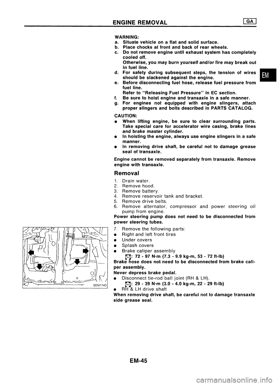
7. Remove thefollowing parts:
• Right andleftfront tires
• Under covers
• Splash covers
• Brake caliper assembly
~: 72-97 N'm (7.3•9.9 kg-m, 53•72 ft-Ib)
Brake hosedoes notneed tobe disconnected frombrake cali-
per assembly.
Never depress brakepedal.
• Disconnect tie-rodballjoint (RH
&
LH).
~: 29-39 N'm (3.0-4.0 kg-m, 22-29 ft-Ib)
• RH
&
LH drive shaft
When removing driveshaft, becareful nottodamage transaxle
side grease seal.
EM-45
•
Page 1241 of 1701
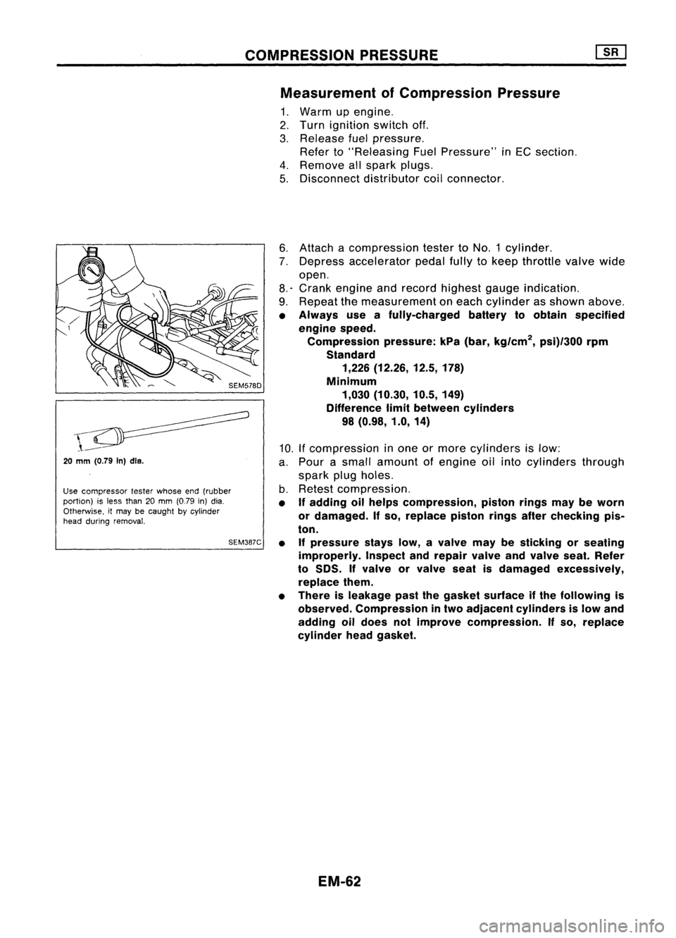
COMPRESSIONPRESSURE
Measurement ofCompression Pressure
1. Warm upengine.
2. Turn ignition switchoff.
3. Release fuelpressure.
Refer to"Releasing FuelPressure" inEC section.
4. Remove allspark plugs.
5. Disconnect distributorcoilconnector.
20
mm (0.79
In)dls.
Use compressor testerwhose end(rubber
portion) isless than 20mm (0.79 in)dia.
Otherwise. itmay becaught bycylinder
head during removal.
SEM387C6.
Attach acompression testertoNO.1 cylinder.
7. Depress accelerator pedalfullytokeep throttle valvewide
open.
8.' Crank engine andrecord highest gaugeindication.
9. Repeat themeasurement oneach cylinder asshown above.
• Always useafully-charged batterytoobtain specified
engine speed.
Compression pressure:kPa(bar, kg/cm
2,
psi)/300 rpm
Standard 1,226 (12.26, 12.5,178)
Minimum 1,030 (10.30, 10.5,149)
Difference limitbetween cylinders
98 (0.98, 1.0,14)
10. Ifcompression inone ormore cylinders islow:
a. Pour asmall amount ofengine oilinto cylinders through
spark plugholes.
b. Retest compression.
• If
adding oilhelps compression, pistonringsmaybeworn
or damaged.
If
so, replace pistonringsafterchecking pis-
ton.
• Ifpressure stayslow,avalve maybesticking orseating
improperly. Inspectandrepair valveandvalve seat.Refer
to
50S.
If
valve orvalve seatisdamaged excessively,
replace them.
• There isleakage pastthegasket surface ifthe following is
observed. Compression intwo adjacent cylinders islow and
adding oildoes notimprove compression.
If
so, replace
cylinder headgasket.
EM-62
Page 1261 of 1701
OILSEAL REPLACEMENT
VALVE OILSEAL
1. Remove accelerator cable.
2. Remove rockercoverandoilseparator.
3. Remove camshafts andsprockets.
Refer to"Removal" in"TIMING CHAIN"(EM-69).
4. Remove sparkplugs.
5. Install airhose adapter intospark plugholeandapply air
pressure tohold valves inplace. Applyapressure of490
kPa (4.9bar, 5kg/cm
2,
71psi).
6. Remove rockerarm,rocker armguide andshim.
Air SEM077D
7.Remove valvespring withTool.
Piston concerned shouldbeset atTOe toprevent valvefrom
falling.
8. Remove valveoilseal.
9. Apply engine oiltonew valve oilseal andinstall itwith Tool.
FRONT OILSEAL
1. Remove thefollowing parts:
• Engine undercover
• Front RHwheel andengine sidecover
• Drive belts
• Crankshaft pulley
2. Remove frontoilseal.
Be careful nottoscratch frontcover.
SEM997C EM-82
Page 1278 of 1701
SEM092DENGINE
REMOVAL
WARNING:
• Situate vehicle onaflat and solid surface.
• Place chocks atfront andback ofrear wheels.
• Donot remove engineuntilexhaust systemhascompletely
cooled off.
Otherwise, youmay burn yourself and/orfiremay break out
in fuel line.
• For safety during subsequent steps,thetension ofwires
should beslackened againsttheengine.
• Before disconnecting fuelhose, release fuelpressure from
fuel line.
Refer to"Releasing FuelPressure" inEC section.
• Besure tohoist engine andtransaxle inasafe manner.
• For engines notequipped withengine slingers, attach
proper slingers andbolts described inPARTS CATALOG.
CAUTION:
• When liftingengine, becareful nottostrike adjacent parts,
especially thefollowing: Accelerator wirecasing, brake
lines, andbrake master cylinder.
• Inhoisting theengine, alwaysuseengine slingers inasafe
manner.
Removal
1. Remove engineundercoverandhood.
2. Drain coolant frombothcylinder block,andradiator.
3. Drain engine oilfrom drain plugofoil pan.
4. Remove vacuumhoses,fuelhoses, wires,harness andcon-
nectors andsoon.
5. Remove exhausttubes,balljoints anddrive shafts.
6. Remove radiatorandfans.
7. Remove drivebelts.
8. Remove alternator, compressor andpower steering oil
pump fromengine.
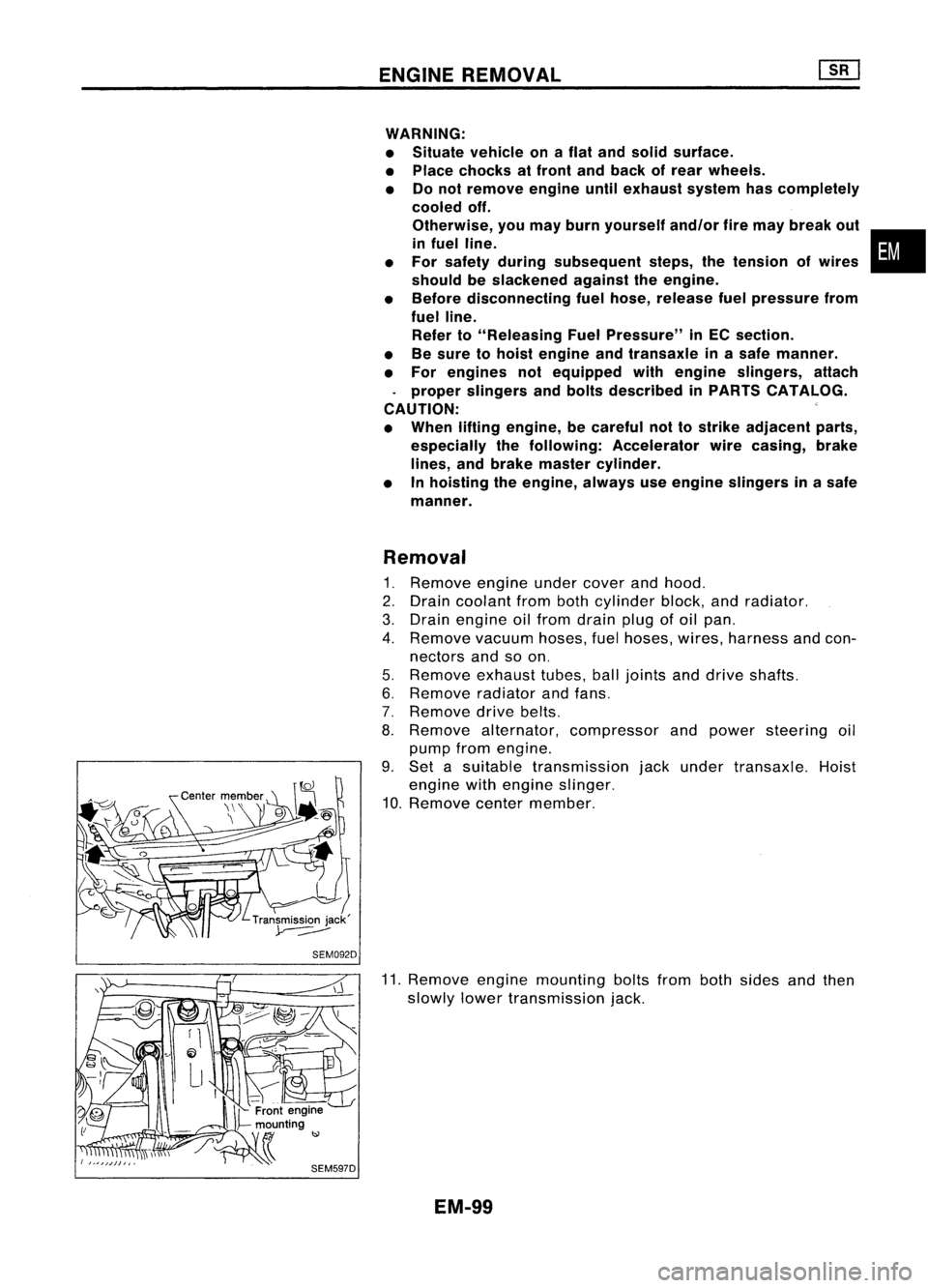
9. Set asuitable transmission jackunder transaxle. Hoist
engine withengine slinger.
10. Remove centermember.
11. Remove enginemounting boltsfrombothsides andthen
slowly lowertransmission jack.
EM-99
•
Page 1295 of 1701
COMPRESSIONPRESSURE
6. Fitcompression gaugetocylinder head.
SEM505D
7.Crank engine andread compression gaugeindication.
Cranking speed:200rpm
Compression pressure:kPa(bar, kg/cm
2,
psi)
Standard
3,138 (31.4, 32,455)
Limit
2,452 (24.5, 25,356)
Limit ofdifference betweencylinders
490 (4.9, 5,71)
8. Ifthe pressure appearslow,pour about 3me (0.11 Impfloz)
of engine oilthrough nozzleholesandrepeat test.
For indications oftest, refer tothe following table.
Gauge indication duringtests Trouble
diagnosis
First
reading Second
reading
Increased
reading
Same reading
maintained
•
Piston ringsareworn ordamaged.
• Iftwo adjacent cylinders arelow, gasket isdamaged .
• Valve issticking .
• Valve seatorvalve contact surface isincorrect.
EM-116