1995 NISSAN ALMERA N15 low oil pressure
[x] Cancel search: low oil pressurePage 1038 of 1701
TROUBLEDIAGNOSIS FORNON-DETECTABLE ITEMS
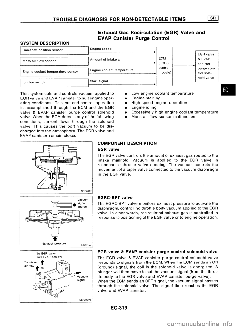
Exhaust GasRecirculation (EGR)Valveand
EVAP Canister PurgeControl
SYSTEM DESCRIPTION
I
Camshaft positionsensor
I
Engine speed
EGRvalve
I
Mass
airflow sensor
I
Amount ofintake air ECM
&
EVAP
(ECCS canister
I
~Engine
coolanttemperature control
purgecon-
Engine coolant temperature sensor
module)trolsole-
I
noid
valve
Ignition switch
I
Start signal
I
This system cutsandcontrols vacuumappliedto
EGR valve andEVAP canister tosuit engine oper-
ating conditions. Thiscut-and-control operation
is accomplished throughtheECM andtheEGR
valve
&
EVAP canister purgecontrol solenoid
valve. WhentheECM detects anyofthe following
conditions, currentflowsthrough thesolenoid
valve. Thiscauses theport vacuum tobe dis-
charged intotheatmosphere. TheEGR valve and
EVAP canister remainclosed.
•
•
•
•
•
•
Low
engine coolant temperature
Engine starting
High-speed engineoperation
Engine idling
Excessively highengine coolant temperature
Mass airflow sensor malfunction
•
Exhaust pressure COMPONENT
DESCRIPTION
EGR valve
The EGR valve controls theamount ofexhaust gasrouted tothe
intake manifold. Vacuumisapplied tothe EGR valve in
response tothrottle valveopening. Thevacuum controls the
movement ofataper valve connected tothe vacuum diaphragm
in the EGR valve.
SEF783K EGRC-BPT valve
The EGRC-BPT valvemonitors exhaustpressure toactivate the
diaphragm, controllingthrottlebodyvacuum appliedtothe EGR
valve. Inother words, recirculated exhaustgasiscontrolled in
response topositioning ofthe EGR valve ortoengine operation.
SEF529K
~ Vacuumsignal
SEF240PE EGR
valve
&
EVAP canister purgecontrol solenoid valve
The EGR valve
&
EVAP canister purgecontrol solenoid valve
responds tosignals fromtheECM. When theECM sends anON
(ground) signal,thecoil inthe solenoid valveisenergized. A
plunger willthen move tocut the vacuum signal(fromthethrot-
tle body tothe EGR valve andEVAP canister purgevalve).
When theECM sends anOFF signal, thevacuum signalpasses
through thesolenoid valve.Thesignal thenreaches theEGR
valve andEVAP canister.
EC-319
Page 1054 of 1701
TROUBLEDIAGNOSIS FORNON-DETECTABLE ITEMS
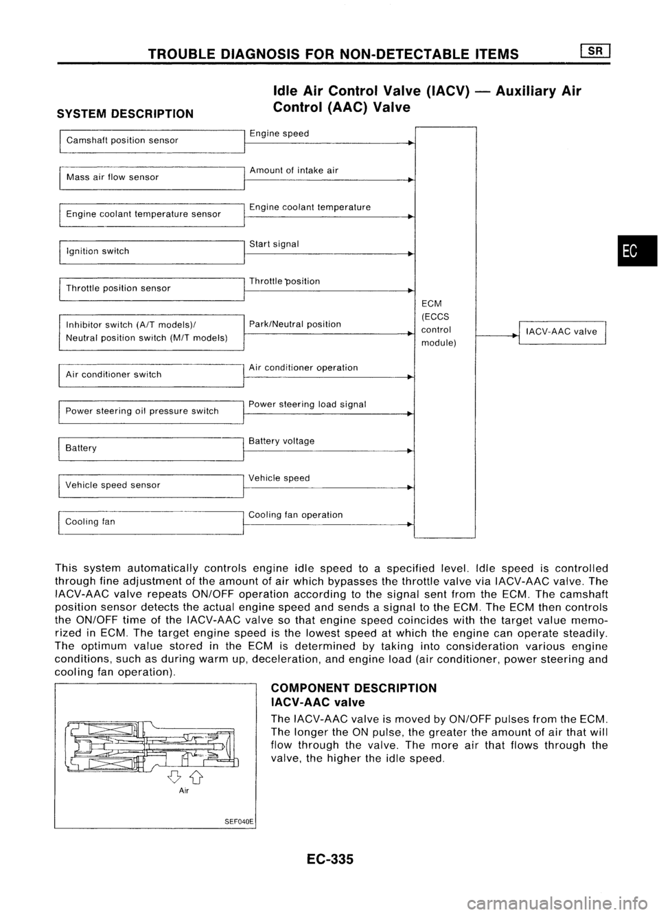
SYSTEM DESCRIPTION Idle
AirControl Valve(IACV) -Auxiliary Air
Control (AAC)Valve
Camshaft positionsensor Engine
speed
~
I
Amount ofintake air
Mass airflow sensor
I
Engine coolant temperature sensor Engine
coolant temperature
I
Ignition switch Start
signal
I
Throttle position sensor Throttle
"position
I
ECM
Inhibitor switch(A/Tmodels)/ Park/Neutral
position (ECCS
control
!
IACV-AAC valve
I
Neutral position switch(M/Tmodels)
module)
Air conditioner switch Air
conditioner operation
Power steering oilpressure switch Power
steering loadsignal
I
Battery Battery
voltage
Vehicle speedsensor Vehicle
speed
I
l
Cooling fan Cooling
fanoperation
I
This system automatically controlsengineidlespeed toaspecified level.Idlespeed iscontrolled
through fineadjustment ofthe amount ofair which bypasses thethrottle valveviaIACV-AAC valve.The
IACV-AAC valverepeats ON/OFF operation according tothe signal sentfrom theECM. Thecamshaft
position sensordetects theactual engine speedandsends asignal tothe ECM. TheECM thencontrols
the ON/OFF timeofthe IACV-AAC valvesothat engine speedcoincides withthetarget valuememo-
rized inECM. Thetarget engine speedisthe lowest speedatwhich theengine canoperate steadily.
The optimum valuestored inthe ECM isdetermined bytaking intoconsideration variousengine
conditions, suchasduring warmup,deceleration, andengine load(airconditioner, powersteering and
cooling fanoperation).
COMPONENTDESCRIPTION
IACV-AAC valve
The IACV-AAC valveismoved byON/OFF pulsesfromtheECM.
The longer theONpulse, thegreater theamount ofair that will
flow through thevalve. Themore airthat flows through the
valve, thehigher theidle speed.
Air SEF040E
EC-335
•
Page 1075 of 1701
TROUBLEDIAGNOSIS FORNON-DETECTABLE ITEMS
mJ
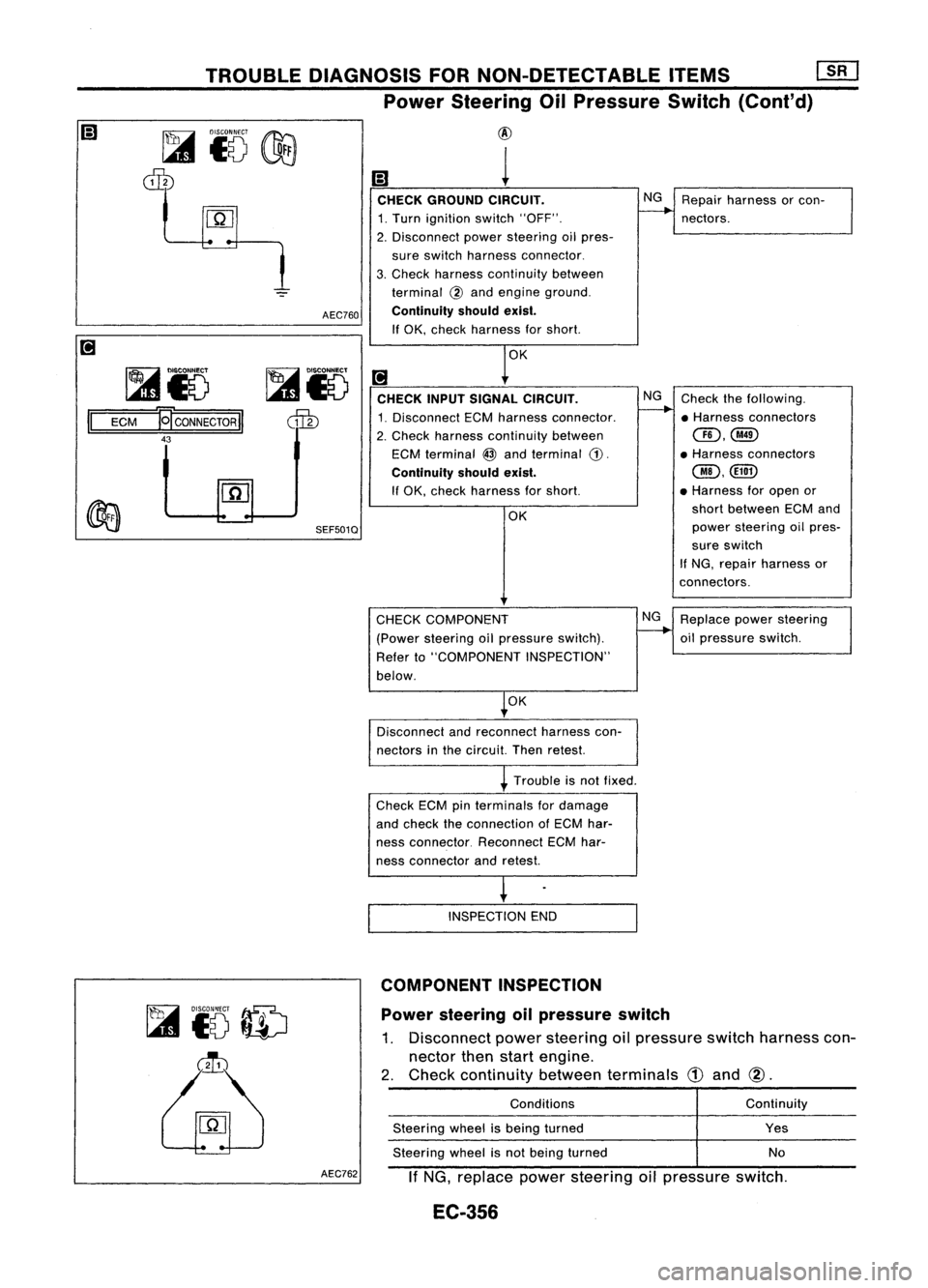
Power Steering OilPressure Switch
(Cont'd)
~i5
dIb
~i5
II
ECM
~CONNECTORII
43 AEC760
SEF501Q
@
1
CHECK GROUND CIRCUIT. NG
Repair harness orcon-
1. Turn ignition switch"OFF".
--..
nectors.
2. Disconnect powersteering oilpres-
sure switch harness connector.
3. Check harness continuity between
terminal
@
and engine ground.
Continuity shouldexist.
If OK, check harness forshort.
OK
[!J
CHECK INPUTSIGNAL CIRCUIT. NG
Check thefollowing.
1. Disconnect ECMharness connector.
--..
•Harness connectors
2. Check harness continuity between
CID,@
ECM terminal
@
and terminal
CD.
•
Harness connectors
Continuity shouldexist.
@,@D
If OK, check harness forshort. •
Harness foropen or
OK short
between ECMand
power steering oilpres-
sure switch
If NG, repair harness or
connectors.
Power steering oilpressure switch
1. Disconnect powersteering oilpressure switchharness con-
nector thenstart engine.
2. Check continuity betweenterminals
CD
and
@.
~
to
ID
~
CHECK
COMPONENT
(Power steering oilpressure switch).
Refer to"COMPONENT INSPECTION"
below.
OK
Disconnect andreconnect harnesscon-
nectors inthe circuit. Thenretest.
Trouble isnot fixed.
Check ECMpinterminals fordamage
and check theconnection ofECM har-
ness connector. ReconnectECMhar-
ness connector andretest.
INSPECTION END
COMPONENT INSPECTION
Conditions
Steering wheelisbeing turned
Steering wheelisnot being turned NG
Replace powersteering
oil pressure switch.
Continuity
Yes
No
AEC762
IfNG, replace powersteering oilpressure switch.
EC-356
Page 1136 of 1701
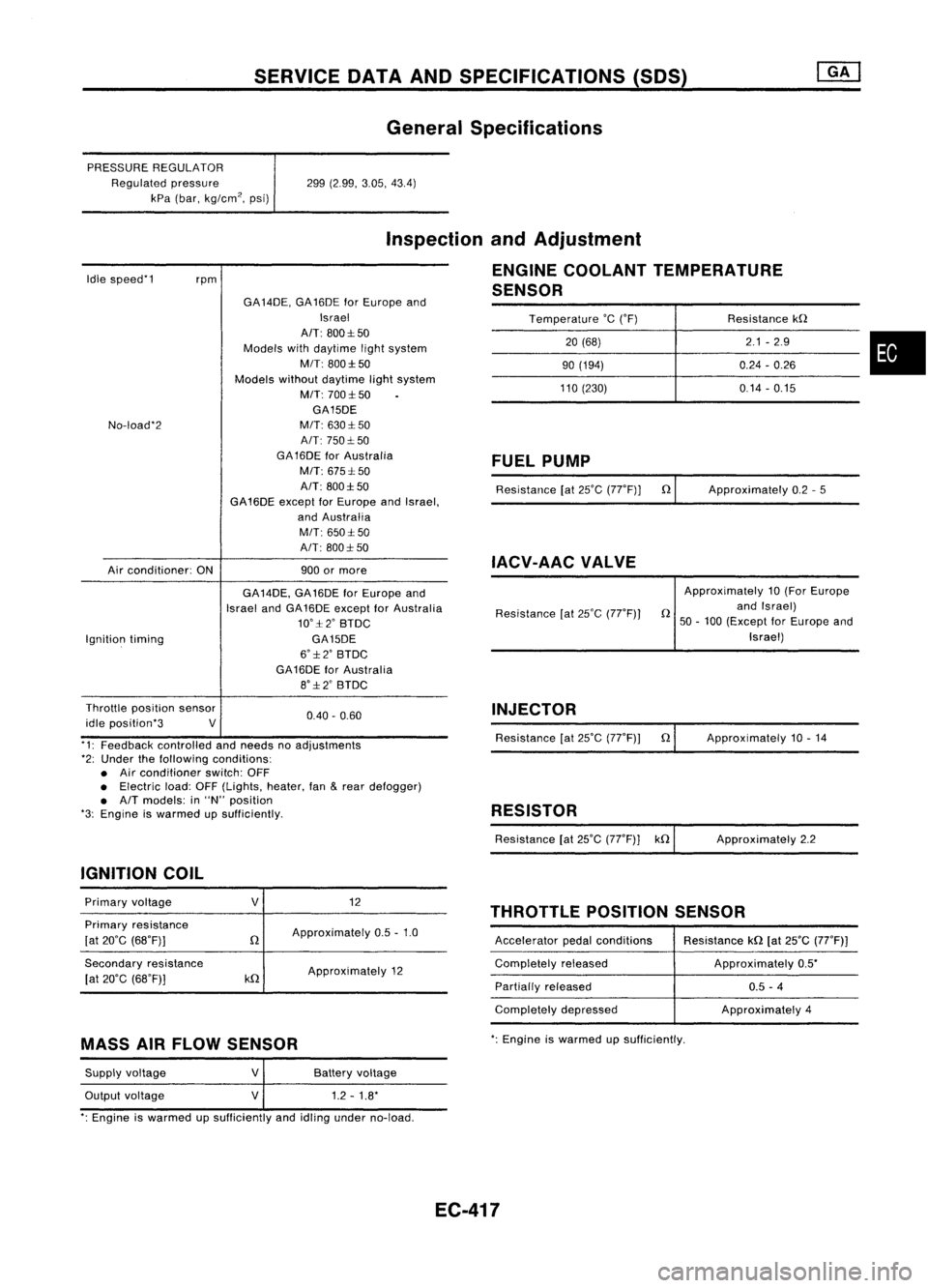
SERVICEDATAANDSPECIFICATIONS (SOS)
General Specifications
PRESSURE REGULATOR
Regulated pressure
kPa (bar, kg/cm
2,
psi) 299
(2.99, 3.05,43.4)
Idle speed'1
rpm
Inspection
andAdjustment
ENGINE COOLANT TEMPERATURE
SENSOR
Temperature
'c
('F) Resistancekn
20 (68) 2.1
-2.9
•
90
(194) 0.24-0.26
110 (230) 0.14-0.15
No-load'2
Air conditioner: ONGA
14DE, GA16DE forEurope and
Israel
AIT: 800:1:50
Models withdaytime lightsystem
MIT: 800:1:50
Models withoutdaytime lightsystem
M/T: 700:1:50
GA15DE
M/T: 630:1: 50
A/T: 750:1: 50
GA 16DE forAustralia
M/T: 675:1: 50
A/T: 800:1:50
GA16DE exceptforEurope andIsrael,
and Australia
M/T: 650:1:50
A/T: 800:1: 50
900 ormore
FUEL
PUMP
Resistance [at25'C (77'F)] n
IACV-AAC VALVE
Approximately
0.2-5
Ignition timing GA
14DE, GA16DE forEurope and
Israel andGA16DE except forAustralia
10':1:2' BTDC
GA15DE
6':1:2' BTDC
GA16DE forAustralia
8':1:2' BTDC Resistance
[at25'C (77'F)) Approximately
10(For Europe
n andIsrael)
50 -100 (Except forEurope and
Israel)
0.40. 0.60
Throttle
position sensor
idle position'3 V
'1: Feedback controlled andneeds noadjustments
'2: Under thefollowing conditions:
• Air conditioner switch:OFF
• Electric load:OFF(Lights, heater,fan
&
rear defogger)
• A/T models: in"N" position
'3: Engine iswarmed upSUfficiently.
IGNITION COIL INJECTOR
Resistance [at25'C (77'F)) n
RESISTOR
Resistance [at25'C (77'F)] kn Approximately
10.14
Approximately 2.2
THROTTLE POSITIONSENSOR
Primary
voltage
Primary resistance
[at 20'C (68'F)]
Secondary resistance
[at 20'C (68'F)]
V
n
kn
12
Approximately 0.5-1.0
Approximately 12 Accelerator
pedalconditions
Completely released
Partially released
Completely depressed Resistance
kn[at25'C (77'F))
Approximately 0.5'
0.5 -4
Approximately 4
MASS AIRFLOW SENSOR
':
Engine iswarmed upsufficiently.
Supply voltage
Output voltage
V
V
Battery
voltage
1.2 -1.8'
': Engine iswarmed upSUfficiently andidling under no-load.
EC-417
Page 1137 of 1701
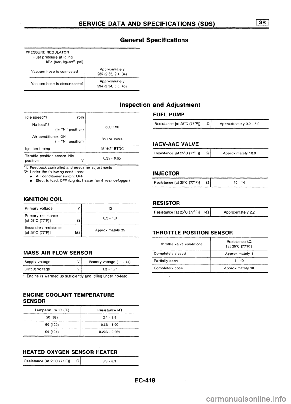
SERVICEDATAANDSPECIFICATIONS (SOS)
General Specifications
PRESSURE REGULATOR
Fuel pressure atidling
kPa (bar, kg/cm
2,
psi)
Vacuum hoseisconnected
Vacuum hoseisdisconnected Approximately
235 (2.35. 2.4.34)
Approxi mately
294 (2.94, 3.0,43)
Idle speed'1
No-load'2 rpm
(in "N" position) 800:1:50
Inspection
andAdjustment
FUEL PUMP
Resistance [at25'C (77'F)] n
Approximately 0.2-5.0
Air conditioner: ON
(in "N" position)
Ignition timing
Throttle position sensoridle
position V850
ormore
IACV-AACVALVE
15':1:2' BTDC
Resistance[at25'C (77'F)] n
0.35 -0.65 Approximately
10.0
'1: Feedback controlled andneeds noadjustments
'2: Under thefollowing conditions:
• Air conditioner switch:OFF
• Electric load:OFF(Lights, heaterfan
&
rear defogger)
IGNITION COIL INJECTOR
Resistance [at25'C (77'F)) n'
1_0_-_1_4 _
RESISTOR
Primary voltage
Primary resistance
[at 25'C (77'F))
V
12
0.5 -1.0 Resistance
[at25'C (77'F)) kn ApproXimately 2.2
Secondary resistance
[at 25'C (77'F))
kn
Approximately
25
THROTTLEPOSITIONSENSOR
MASS AIRFLOW SENSOR
Supply voltage
Output voltage
V
V
Battery
voltage (11-14)
1.3 -1.7'
Throttle
valveconditions
Completely closed
Partially open
Completely open Resistance
kn
[at 25'C (77'F)]
Approximately 1
1 - 10
Approximately 10
': Engine iswarmed upsufficiently andidling under no-load.
ENGINE COOLANT TEMPERATURE
SENSOR
Temperature
'c
('F)
20 (68)
50 (122)
90 (194) Resistance
kn
2.1-2.9
0.68 -1.00
0.236 -0.260
HEATED OXYGEN SENSOR HEATER
Resistance [at25'C (77'F)] n
I
3.3-6.3
EC-418
Page 1158 of 1701
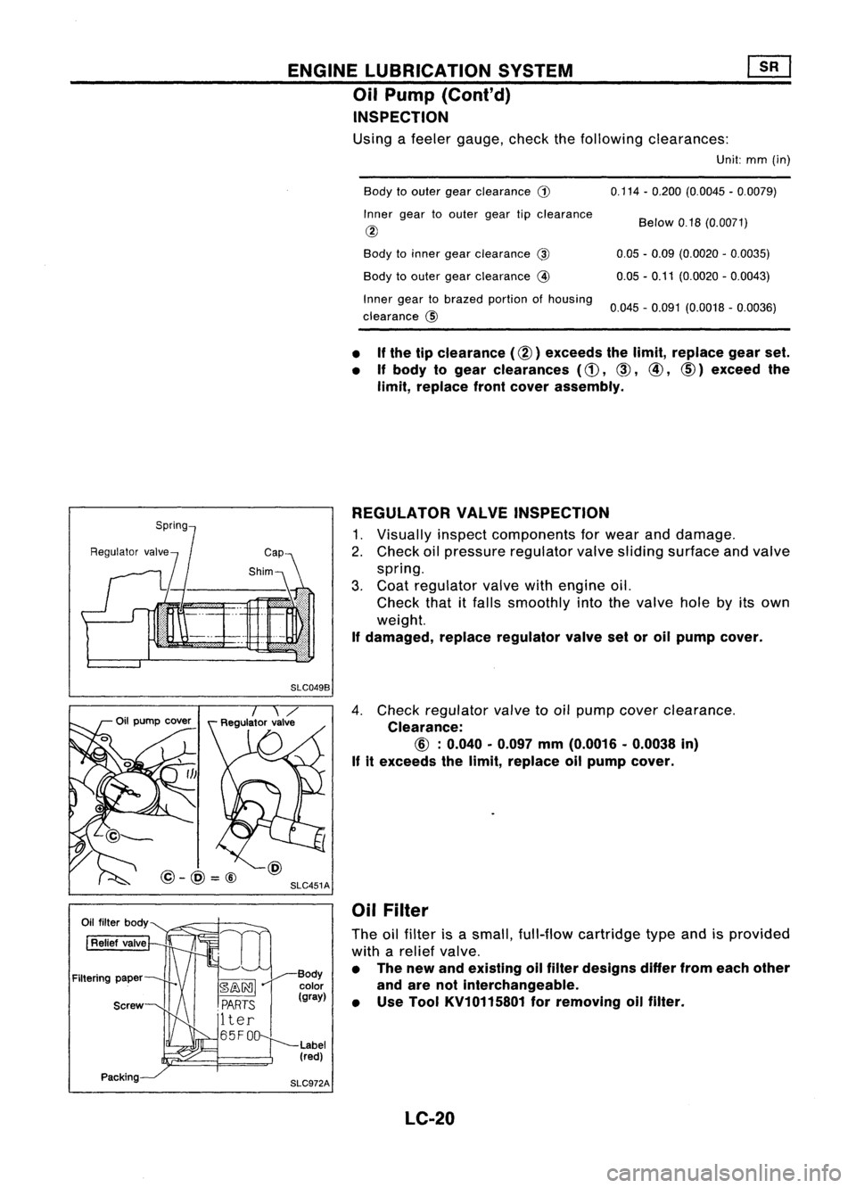
ENGINELUBRICATION SYSTEM
Oil Pump (Cont'd)
INSPECTION
Using afeeler gauge, checkthefollowing clearances:
Unit:mm(in)
Body toouter gearclearance
G)
Inner geartoouter geartipclearance
@
Body toinner gearclearance
@
Body toouter gearclearance
@
Inner geartobrazed portionofhousing
clearance @ 0.114
-0.200 (0.0045 -0.0079)
Below 0.18(0.0071)
0.05 -0.09 (0.0020 -0.0035)
0.05 -0.11 (0.0020 -0.0043)
0.045 -0.091 (0.0018 -0.0036)
• If
the tipclearance (@) exceeds thelimit, replace gearset.
• Ifbody togear clearances
(d),
CID,
@,
CID)
exceed the
limit, replace frontcover assembly.
REGULATOR VALVEINSPECTION
1. Visually inspectcomponents forwear anddamage.
2. Check oilpressure regulator valvesliding surface andvalve
spring.
3. Coat regulator valvewithengine oil.
Check thatitfalls smoothly intothevalve holebyitsown
weight.
If damaged, replaceregulator valvesetoroil pump cover.
SLC049B
SLC451A
@-@=@
4.
Check regulator valvetooil pump cover clearance.
Clearance:
If
itexceeds thelimit, replace oilpump cover.
Oil Filter
The oilfilter isasmall, full-flow cartridge typeandisprovided
with arelief valve.
• The new andeXisting oilfilter designs differfromeach other
and arenotinterchangeable.
• Use Tool KV10115801 forremoving oilfilter.
LC-20
Page 1167 of 1701
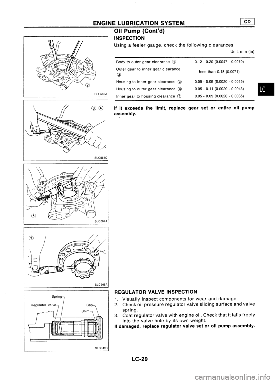
•
less
than 0.18(0.0071)
0.12
-0.20 (0.0047 -0.0079)
0.05 -0.09 (0.0020 -0.0035)
0.05 -0.11 (0.0020 -0.0043)
0.05 -0.09 (0.0020 -0.0035)
Body
toouter gearclearance
CD
Outer geartoinner gearclearance
@
Housing toinner gearclearance @
Housing toouter gearclearance
@
Inner geartohousing clearance @
If
itexceeds thelimit, replace gearsetorentire oilpump
assembly.
SLC560A
ENGINE
LUBRICATION SYSTEM
Oil Pump (Cont'd)
INSPECTION
Using afeeler gauge, checkthefollowing clearances.
Unit:mm(in)
SLC561C
SLC568A REGULATOR VALVEINSPECTION
1. Visually inspectcomponents forwear anddamage.
2. Check oilpressure regulator valvesliding surface andvalve
spring.
3. Coat regulator valvewithengine oil.Check that
it
falls freely
into thevalve holebyitsown weight.
If
damaged, replaceregulator valvesetoroil pump assembly.
SLC049B LC-29
Page 1168 of 1701
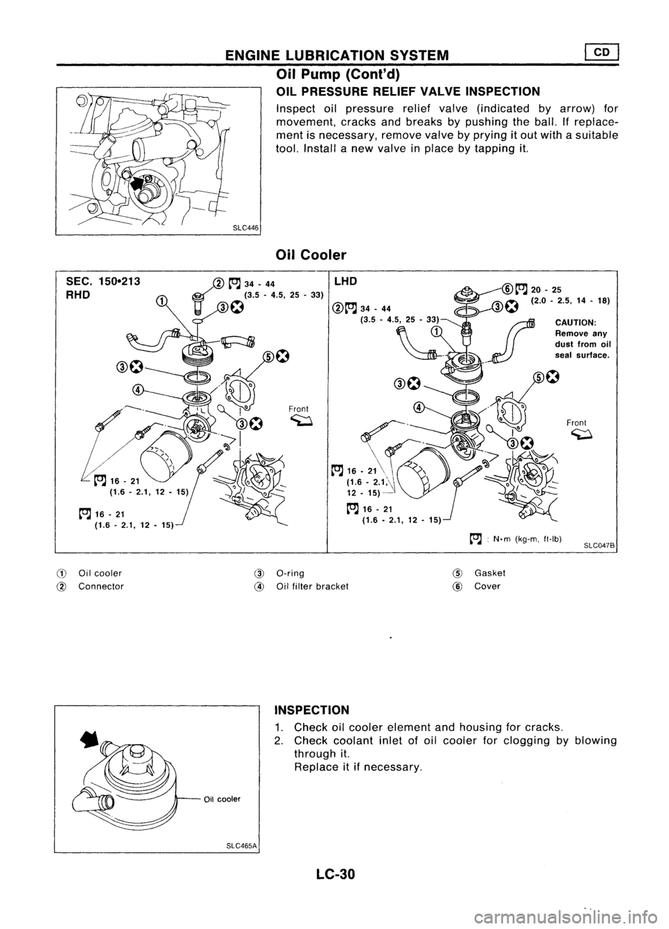
ENGINELUBRICATION SYSTEM
Oil Pump (Cont'd)
OIL PRESSURE RELIEFVALVEINSPECTION
Inspect oilpressure reliefvalve (indicated byarrow) for
movement, cracksandbreaks bypushing theball. Ifreplace-
ment isnecessary, removevalvebyprying itout with asuitable
tool. Install anew valve inplace bytapping it.
SLC446 OilCooler
SEC. 150-213
RHO
tOJ
16-21
(1.6. 2.1,12•15)
/
tOJ
34-44
11 ~
f:1
(3.5 -4.5, 25-33)
Front ~ LHO
:N.m (kg-m, ft-Ib)
Front
~
SLC047B
CD
Oilcooler
@
Connector
@
a-ring
@
Oilfilter bracket
@
Gasket
@
Cover
INSPECTION
1. Check oilcooler element andhousing forcracks.
2. Check coolant inletofoil cooler forclogging byblowing
through it.
Replace itifnecessary.
Oil cooler
SLC465A LC-30