1995 NISSAN ALMERA N15 low oil pressure
[x] Cancel search: low oil pressurePage 447 of 1701
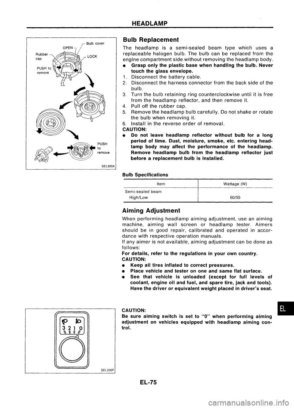
Bulbcover
SEL995K HEADLAMP
Bulb Replacement
The headlamp isasemi-sealed beamtypewhich usesa
replaceable halogenbulb.Thebulb canbereplaced fromthe
engine compartment sidewithout removing theheadlamp body.
• Grasp onlytheplastic basewhen handling thebulb. Never
touch theglass envelope.
1. Disconnect thebattery cable.
2. Disconnect theharness connector fromtheback sideofthe
bulb.
3. Turn thebulb retaining ringcounterclockwise until
it
is free
from theheadlamp reflector,andthen remove it.
4. Pull offthe rubber cap.
5. Remove theheadlamp bulbcarefully. Donot shake orrotate
the bulb when removing it.
6. Install inthe reverse orderofremoval.
CAUTION:
• Do not leave headlamp reflector withoutbulbforalong
period oftime. Dust,moisture, smoke,etc.entering head-
lamp bodymayaffect theperformance ofthe head lamp.
Remove headlamp bulbfrom thehead lamp reflector just
before areplacement bulbisinstalled.
Bulb Specifications
Item
Semi-sealed beam
High/Low Wattage
(W)
60/55
f>
to
3 21 0
~ nOD
o
SEL226PAiming
Adjustment
When performing headlamp aiming adjustment, useanaiming
machine, aimingwallscreen orheadlamp tester.Aimers
should beingood repair, calibrated andoperated inaccor-
dance withrespective operationmanuals.
If any aimer isnot available, aimingadjustment canbedone as
follows:
For details, refertothe regulations inyour owncountry.
CAUTION:
• Keep alltires inflated tocorrect pressures.
• Place vehicle andtester onone and same flatsurface.
• See thatvehicle isunloaded (exceptforfull levels of
coolant, engineoiland fuel, andspare tire,jack andtools).
Have thedriver orequivalent weightplaced indriver's seat.
CAUTION: •
Be sure aiming switchisset to
"0"
when performing aiming
adjustment onvehicles equipped withheadlamp aiming con-
trol.
EL-75
Page 473 of 1701
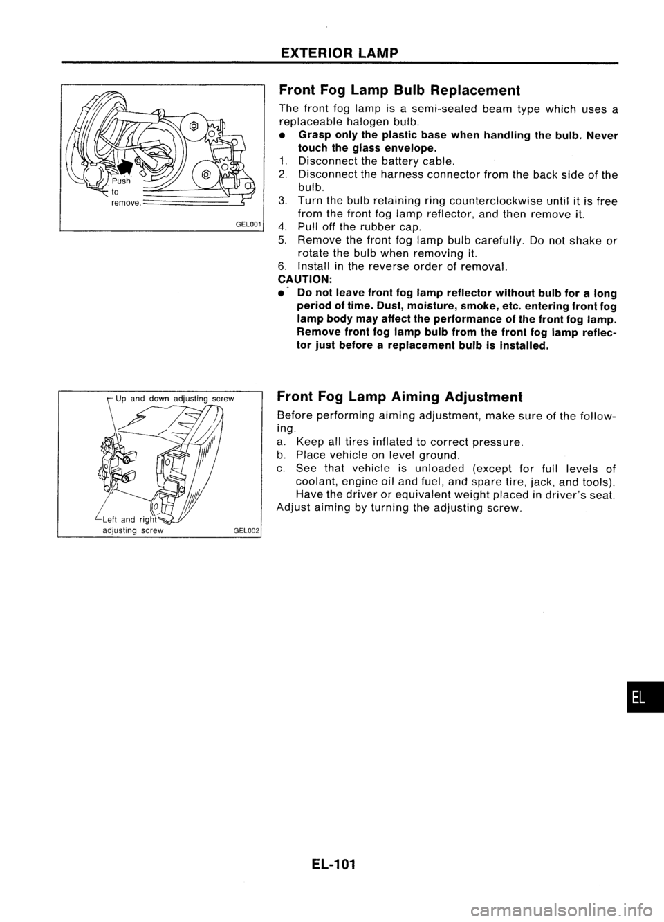
GEL001EXTERIOR
LAMP
Front FogLamp BulbReplacement
The front foglamp isasemi-sealed beamtypewhich usesa
replaceable halogenbulb.
• Grasp onlytheplastic basewhen handling thebulb. Never
touch theglass envelope.
1. Disconnect thebattery cable.
2. Disconnect theharness connector fromtheback sideofthe
bulb.
3. Turn thebulb retaining ringcounterclockwise untilitis free
from thefront foglamp reflector, andthen remove it.
4. Pull offthe rubber cap.
5. Remove thefront foglamp bulbcarefully. Donot shake or
rotate thebulb when removing it.
6. Install inthe reverse orderofremoval.
CAUTION:
.' Donot leave frontfoglamp reflector withoutbulbforalong
period oftime. Dust, moisture, smoke,etc.entering frontfog
lamp bodymayaffect theperformance ofthe front foglamp.
Remove frontfoglamp bulbfrom thefront foglamp reflec-
tor just before areplacement bulbisinstalled.
Front FogLamp Aiming Adjustment
Before performing aimingadjustment, makesureofthe follow-
ing.
a. Keep alltires inflated tocorrect pressure.
b. Place vehicle onlevel ground.
c. See thatvehicle isunloaded (exceptforfull levels of
coolant, engineoiland fuel, andspare tire,jack, andtools).
Have thedriver orequivalent weightplaced indriver's seat.
Adjust aiming byturning theadjusting screw.
EL-101
•
Page 510 of 1701
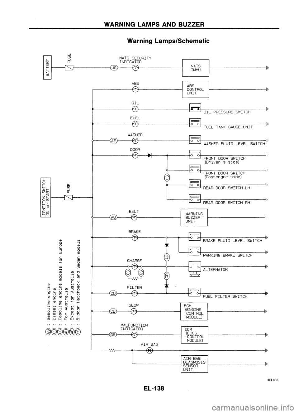
WARNINGLAMPSANDBUZZER
Warning Lamps/Schematic
>-
[[
W
f-
f-
CD
w
(f)
:J
l.L
UG
NATS
SECURITY
INDICATOR
NATSIMMU
ABS ABS
CONTROL
UNIT
OIL OILPRESSURE SWITCH
FUEL
FUELTANKGAUGE UNIT
WASHER
WASHERFLUIDLEVELSWITCH
DOOR
FRONTDOORSWITCH
(Driver's side)
FRONT DOORSWITCH
(Passenger side)
REAR ODOR SWITCH LH
ALTERNATOR PARKING
BRAKESWITCH
FUEL FILTER SWITCH
=
BRAKE
FLUIDLEVEL SWITCH
REAR
ODORSWITCH RH
=
WARNING
BUZZER
UNIT
=
ECM (ECCS
CONTROL
MODULE)
ECM
(ENGINE
CONTROL
MODULE)
I
U
f- W
H (f)
3:f-
:J
(f)[[
l.L
Zf-
O(f)
H
f-L
HO
Z
BELT
C!JZ
HO
BRAKE
Q)
(I)
D.
rl
0
Q)
L
D
::J
0
W
E
L
C
0
ro
""-
D
Q)
(I)
(f)
rl
Q)
ro
D
D
'M
C
0
rl
ro
E
ro
L
~
Q) Q)
.....
u
C C
(I)
ro
.M
Q)
.M
ro
::J
.0
OJ
C
OJ
.M
c
.M
C
rl
U
Q)
OJ
Q)
ro
L
+'
C
L
0
ro
Q) Q) Q)
.....
""-
I
C C
(I)
GLOW
.M
rl
.
M
::J
.....
L
rl
Q)
rl
0
0
(I)
0
Q)
0
(I)
Q)
(I)
L
u
D
ro
.M
ro
0
x
I
C!J
0
C!J
l.L
W
lD
MALFUNCTION
@@~@@@
INDICATOR
AIRBAG
AIRBAG
DIAGNOSIS
SENSOR
UNIT
HEL082
EL-138
Page 519 of 1701
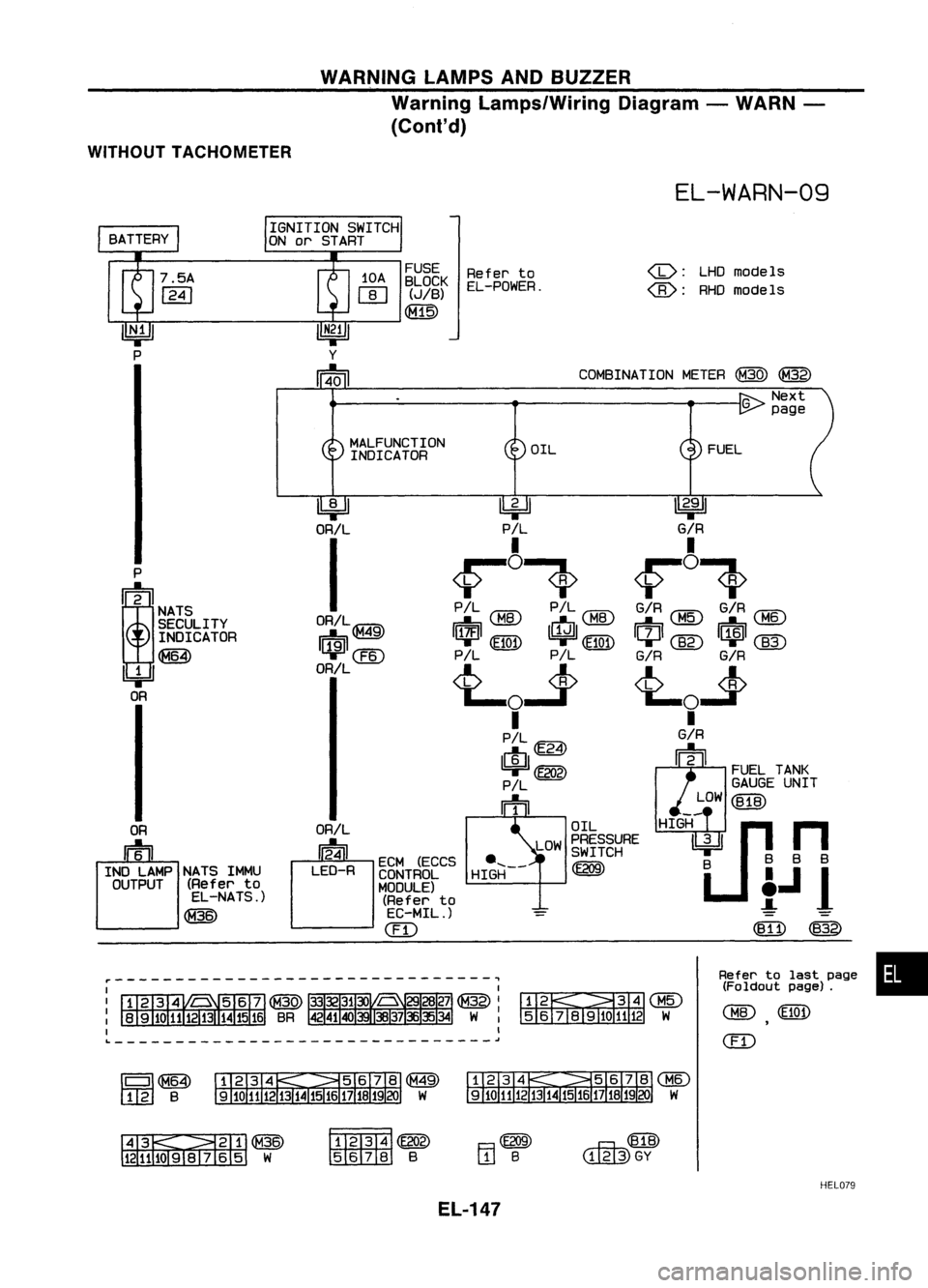
WARNINGLAMPSANDBUZZER
Warning Lamps/Wiring Diagram-WARN -
(Cont'd)
WITHOUT TACHOMETER
EL-WARN-09
FUELTANK
GAUGE UNIT
LOW (818)
HIGH
r.n
n
~ 888
B
i.Jl
FUEL
:
LHDmodels
@:
RHOmodels
~
G/R
I
1>
G/R ~ G/R~
1c!J1
@
1$1
(@
G/R G/R
~O~
I
G/R
m
OIL
LOW PRESSURE
SWITCH
HI~H-- ~
OIL
~
P/L
I
~01>
P
IL
f'UCi"\
P/L
f'UCi"\
~~ ~~
III7FII IlJdjl
T"' ~
'9F
(El0n
P/L P/L
t...oJ>
I
P/L~
c!J1illI
~(E202)
P/L
m
FUSE
Referto
8LOCK EL-POWER.
(J/8)
~
MALFUNCTION INDICATOR
~
ORIL
I
ORIL
Illii'n\
1i1'9il~
~@
ORIL
ORIL
0
24
LEO
RECM (ECCS
- CONTROL
MODULE) (Refer to
EC-MIL.)
ill)
P
;
NATS
SECULITY
INDICATOR
~
4=Jl
OR
OR
IFh
INO LAMP NATSIMMU
OUTPUT (Referto
EL-NATS.)
@>
L- __ --'
~-------------------------------~
~~@
5 6j819iO 1112W
Refer
tolast page •
(Foldout page).
CHID
(E10!)
ill)
IIIII~
128
~~@
l21U091V 65 W ~(E202)
rn::rn:rz::tm
8
([j])
<:lliTI)
GY
HEL079
EL-147
Page 721 of 1701
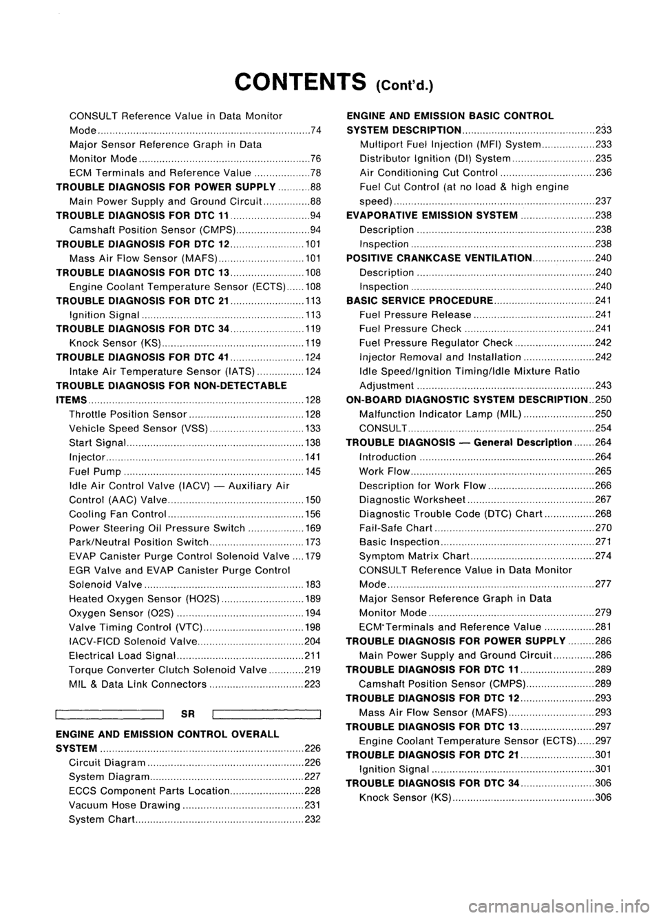
CONTENTS(Cont'd.)
CONSULT Reference ValueinData Monitor
Mode 74
Major Sensor Reference GraphinData
Monitor Mode 76
ECM Terminals andReference Value 78
TROUBLE DIAGNOSIS FORPOWER SUPPLY 88
Main Power Supply andGround Circuit.. 88
TROUBLE DIAGNOSIS FORDTC11 94
Camshaft PositionSensor(CMPS) 94
TROUBLE DIAGNOSIS FORDTC
12 101
Mass AirFlow Sensor (MAFS) 101
TROUBLE DIAGNOSIS FORDTC
13 108
Engine Coolant Temperature Sensor(ECTS) 108
TROUBLE DIAGNOSIS FORDTC
21 113
Ignition Signal 113
TROUBLE DIAGNOSIS FORDTC
34 119
Knock Sensor (KS) 119
TROUBLE DIAGNOSIS FORDTC
41 124
Intake AirTemperature Sensor(IATS) 124
TROUBLE DIAGNOSIS FORNON-DETECTABLE
ITEMS , '"
.128
Throttle Position Sensor 128
Vehicle SpeedSensor (VSS) 133
Start Signal 138
Injector 141
Fuel Pump 145
Idle AirControl Valve(IACV) -Auxiliary Air
Control (AAC)Valve 150
Cooling FanControl 156
Power Steering OilPressure Switch 169
Park/Neutral PositionSwitch 173
EVAP Canister PurgeControl Solenoid Valve179
EGR Valve andEVAP Canister PurgeControl
Solenoid Valve 183
Heated Oxygen Sensor(H02S) 189
Oxygen Sensor(02S) 194
Valve Timing Control (VTC) 198
IACV-FICD SolenoidValve 204
Electrical LoadSignal 211
Torque Converter ClutchSolenoid Valve 219
MIL
&
Data LinkConnectors 223
SR
ENGINE ANDEMISSION CONTROL OVERALL
SYSTE M
226
Circuit Diagram 226
System Diagram 227
ECCS Component PartsLocation 228
Vacuum HoseDrawing 231
System Chart... 232
ENGINE
ANDEMISSION BASICCONTROL
SYSTEM DESCRiPTION
233
Multipart FuelInjection (MFI)System 233
Distributor Ignition
(01)
System 235
Air Conditioning CutControl 236
Fuel CutControl (atnoload
&
high engine
speed) 237
EVAPORATIVE EMISSIONSYSTEM
238
Description 238
Inspection 238
POSITIVE CRANKCASE VENTILATION
240
Description 240
Inspection 240
BASIC SERVICE
PROCEDURE 241
Fuel Pressure Release 241
Fuel Pressure Check 241
Fuel Pressure Regulator Check 242
Injector Removal andInstallation 242
Idle Speed/Ignition Timing/IdleMixtureRatio
Adjustment 243
ON-BOARD DIAGNOSTIC SYSTEMDESCRIPTION ..250
Malfunction IndicatorLamp(MIL) 250
CONSULT 254
TROUBLE DIAGNOSIS -General Description
264
Introduction 264
Work Flow 265
Description forWork Flow 266
Diagnostic Worksheet 267
Diagnostic TroubleCode(DTC) Chart 268
Fail-Safe Chart 270
Basic Inspection 271
Symptom MatrixChart. 274
CONSULT Reference ValueinData Monitor
Mode 277
Major Sensor Reference GraphinData
Monitor Mode 279
ECM"Terminals andReference Value 281
TROUBLE DIAGNOSIS FORPOWER SUPPLY
286
Main Power Supply andGround Circuit.. 286
TROUBLE DIAGNOSIS FORDTC
11 289
Camshaft PositionSensor(CMPS) 289
TROUBLE DIAGNOSIS FORDTC
12 293
Mass AirFlow Sensor (MAFS) 293
TROUBLE DIAGNOSIS FORDTC
13 297
Engine Coolant Temperature Sensor(ECTS) 297
TROUBLE DIAGNOSIS FORDTC
21 301
Ignition Signal 301
TROUBLE DIAGNOSIS FORDTC
34 306
Knock Sensor (KS) 306
Page 722 of 1701
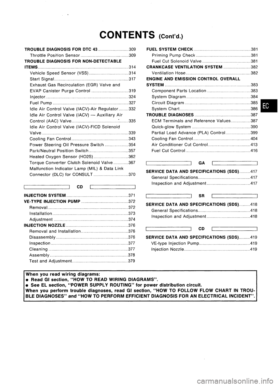
CONTENTS(Cont'd.)
TROUBLE DIAGNOSIS FORDTC
43 309
Throttle Position Sensor 309
TROUBLE DIAGNOSIS FORNON-DETECTABLE
ITEMS
314
Vehicle SpeedSensor (VSS) 314
Start Signal 317
Exhaust GasRecirculation (EGR)Valveand
EVAP Canister PurgeControl 319
Injector 324
Fuel Pump 327
Idle AirControl Valve(IACV)-Air Regulator 332
Idle AirControl Valve(IACV) -Auxiliary Air
Control (AAC)Valve :335
Idle AirControl Valve(IACV)-FICD Solenoid
Valve '"339
Cooling FanControl 343
Power Steering OilPressure Switch 354
Park/Neutral PositionSwitch 357
Heated Oxygen Sensor(H02S) 362
Torque
Converter
ClutchSolenoid Valve 367
Malfunction IndicatorLamp(MIL)
&
Data Link
Connector (DLC)forCONSULT 370
CD
INJECTION SYSTEM
371
VE.TYPE INJECTION PUMP
372
Removal 372
Installation 373
Adjustment 374
INJECTION NOZZLE
376
Removal andInstallation 376
Disassembly 376
Inspection 377
Cleaning 377
Assembly 378
Test andAdjustment 379
FUEL
SYSTEM CHECK
381
Priming PumpCheck 381
Fuel CutSolenoid Valve 381
CRANKCASE VENTILATION SYSTEM
382
Ventilation Hose 382
ENGINE ANDEMISSION CONTROLOVERALL
SYSTEM
383
Component PartsLocation 383
System Diagram 384
Circuit Diagram ,385
System Chart. 386
TROUBLE DIAGNOSES
387
ECM Terminals andReference Values 387
Quick-glow System 390
Partial LoadAdvance (PLA)Control 399
Cooling FanControl 404
Air Conditioner CutControl 413
Fuel CutControl 416
GA
SERVICE DATAANDSPECIFICATIONS
(505).417
General Specifications 417
Inspection andAdjustment.. 417
SR
SERVICE DATAANDSPECIFICATIONS
(505).418
General Specifications 418
Inspection andAdjustment.. .418
CD
SERVICE DATAANDSPECIFICATIONS
(505).419
VE-type Injection Pump 419
Injection Nozzle 419
•
When youread wiring diagrams:
• Read GIsection, "HOWTOREAD WIRING DIAGRAMS" .
• See Elsection, "POWER SUPPLYROUTING" forpower distribution circuit.
When youperform troublediagnoses, readGIsection, "HOWTOFOllOW FLOWCHART INTROU-
BLE DIAGNOSES" and"HOW TOPERFORM EFFICIENT DIAGNOSIS FORANELECTRICAL INCIDENT".
Page 736 of 1701
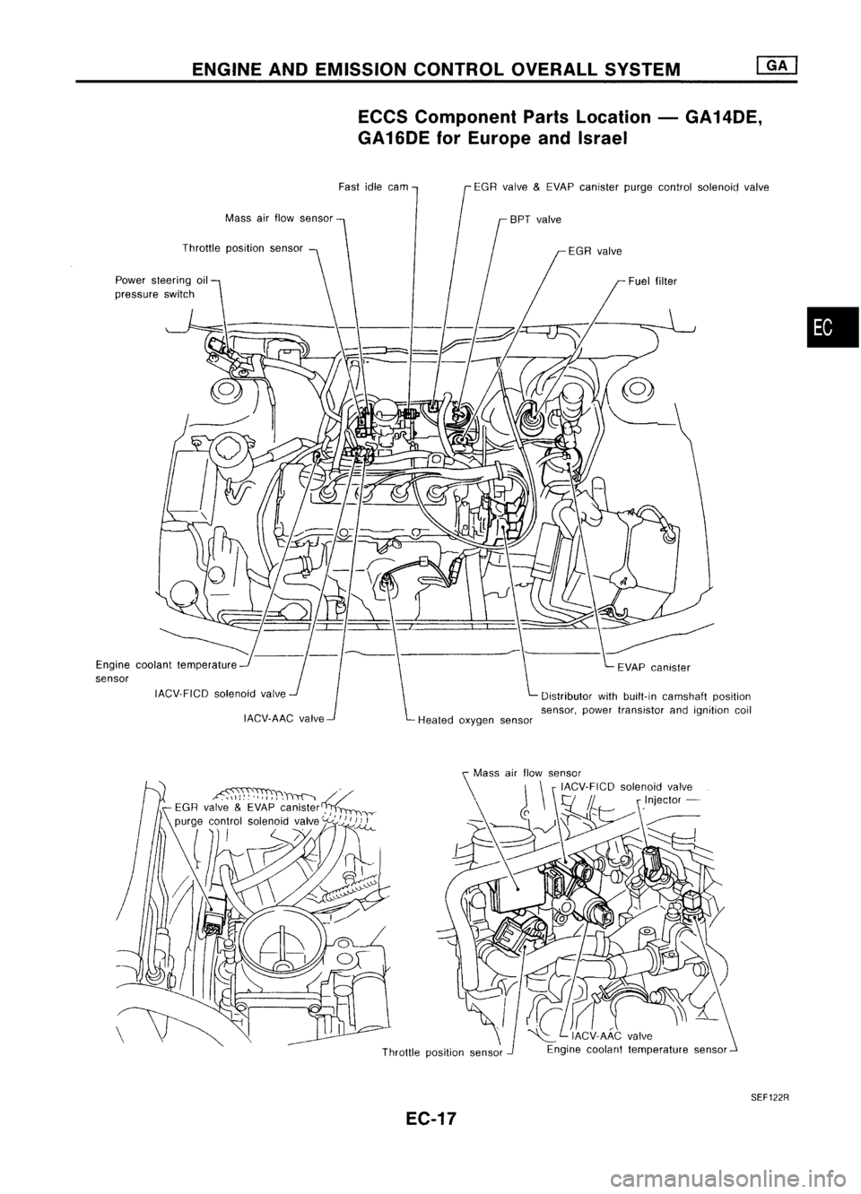
ENGINEANDEMISSION CONTROLOVERALLSYSTEM
ECCS Component PartsLocation -GA14DE,
GA 16DE forEurope andIsrael
Mass airflow sensor
Throttle positionsensor
Power steering oil
pressure switch
Engine coolant temperature
sensor
IACV-FICDsolenoidvalve
IACV-AAC valveFast
idlecam EGRvalve
&
EVAP canister purgecontrol solenoid valve
Distributor withbuilt-in camshaft position
sensor, powertransistor andignition coil
•
Throttle positionsensor
SEF122R
EC-17
Page 742 of 1701
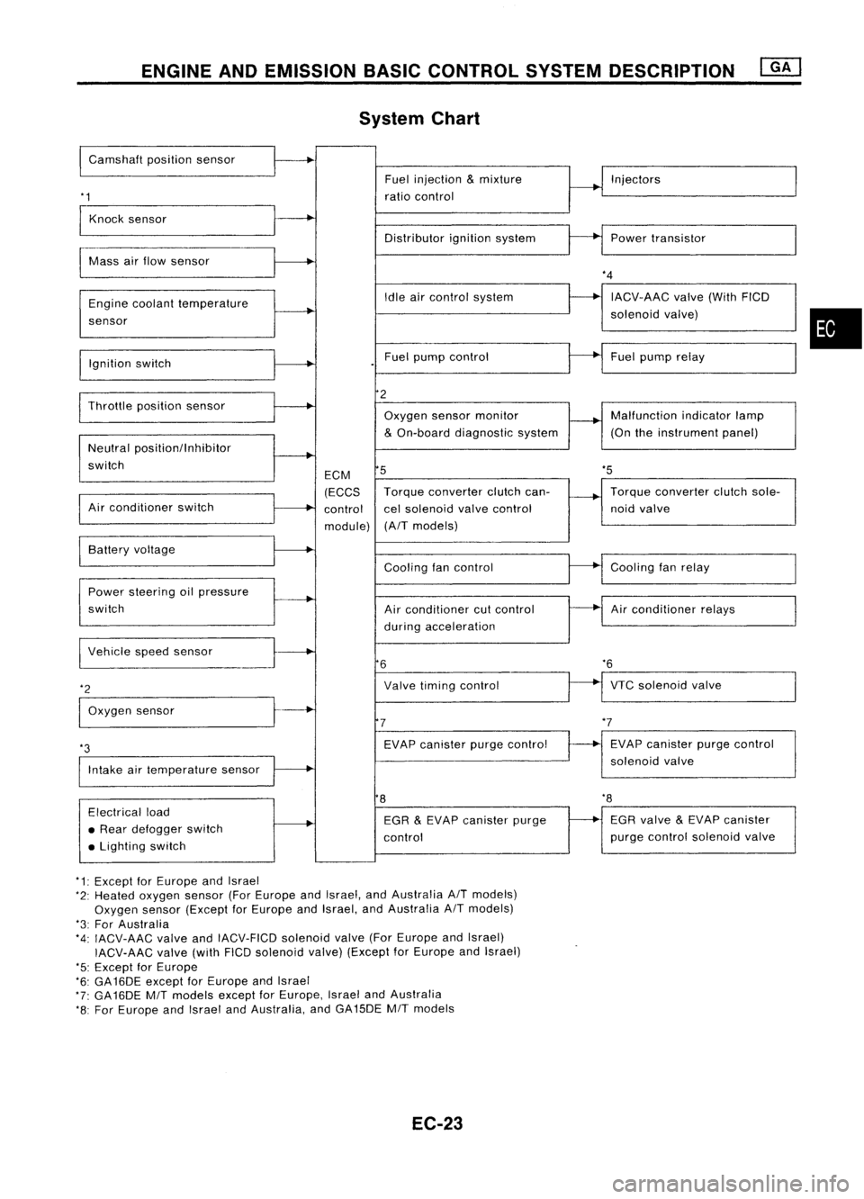
ENGINEANDEMISSION BASICCONTROL SYSTEMDESCRIPTION
System Chart
I
Camshaft positionsensor
'1
Fuel
injection
&
mixture
ratio control Injectors
Knock sensor
Distributorignitionsystem Powertransistor
Mass airflow sensor
Engine coolant temperature
sensor
Ignition switch Idle
aircontrol system
Fuel pump control
*4
IACV-AAC valve(WithFICD
solenoid valve)
Fuel pump relay
•
'5
Throttle
positionsensor
Neutral positionllnhibitor
switch
Air conditioner switch ECM
(ECCS
control
module)
2
Oxygen sensormonitor
&
On-board diagnostic system
5
Torque converter clutchcan-
cel solenoid valvecontrol
(A/T models) Malfunction
indicatorlamp
(On theinstrument panel)
Torque converter clutchsole-
noid valve
VTC solenoid valve
*6
Air
conditioner relays
Cooling
fanrelay
EVAP canister purgecontrol
solenoid valve
Cooling
fancontrol
Air conditioner cutcontrol
during acceleration
Valve timing control
EVAP canister purgecontrol
7
6
Power
steering oilpressure
switch Battery
voltage
Intake airtemperature sensor
*3
I
Vehicle speedsensor
*2
I
Oxygen sensor
8
'8
Electrical load
• Rear defogger switch
• Lighting switch EGR
&
EVAP canister purge
control EGR
valve
&
EVAP canister
purge control solenoid valve
*1: Except forEurope andIsrael
*2: Heated oxygen sensor(ForEurope andIsrael, andAustralia A/Tmodels)
Oxygen sensor(Except forEurope andIsrael, andAustralia A/Tmodels)
*3: For Australia
*4: IACV-AAC valveandIACV-FICD solenoidvalve(ForEurope andIsrael)
IACV-AAC valve(withFICDsolenoid valve)(Except forEurope andIsrael)
'5: Except forEurope
*6: GA16DE exceptforEurope andIsrael
*7: GA16DE MITmodels exceptforEurope, IsraelandAustralia
*8: For Europe andIsrael andAustralia, andGA15DE MITmodels
EC-23