1995 NISSAN ALMERA N15 low oil pressure
[x] Cancel search: low oil pressurePage 917 of 1701
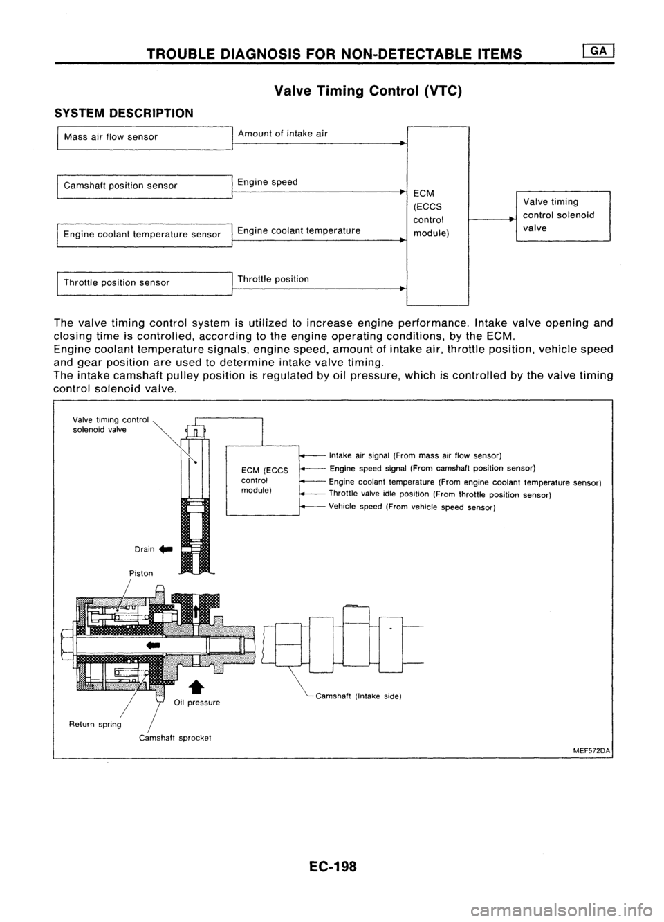
TROUBLEDIAGNOSIS FORNON-DETECTABLE ITEMS
Valve Timing Control (VTC)
SYSTEM DESCRIPTION
Mass airflow sensor Amount
ofintake air
Camshaft positionsensor Enginespeed
Engine coolant temperature sensorEnginecoolant temperature ECM
(ECCS
control module) Valve
timing
control solenoid
valve
Throttle positionsensor Throttle
position
The valve timing control system isutilized toincrease engineperformance. Intakevalveopening and
closing timeiscontrolled, accordingtothe engine operating conditions, bythe ECM.
Engine coolant temperature signals,enginespeed,amount ofintake air,throttle position, vehiclespeed
and gear position areused todetermine intakevalvetiming.
The intake camshaft pulleyposition isregulated byoil pressure, whichiscontrolled bythe valve timing
control solenoid valve.
Drain .. Intake
airsignal (From massairflow sensor)
Engine speedsignal(From camshaft positionsensor)
Engine coolant temperature (Fromengine coolant temperature sensor)
Throttle valveidleposition (Fromthrottle position sensor)
Vehicle speed(Fromvehicle speedsensor)
"'- Camshaft (Intakeside)
EGM
(EGGS
control
module)
/
Camshaft sprocket
Piston
Valve
timing control ~
»
'o'""oid ,,',"
Ii
/
Return spring
MEF572DA
EC-198
Page 951 of 1701
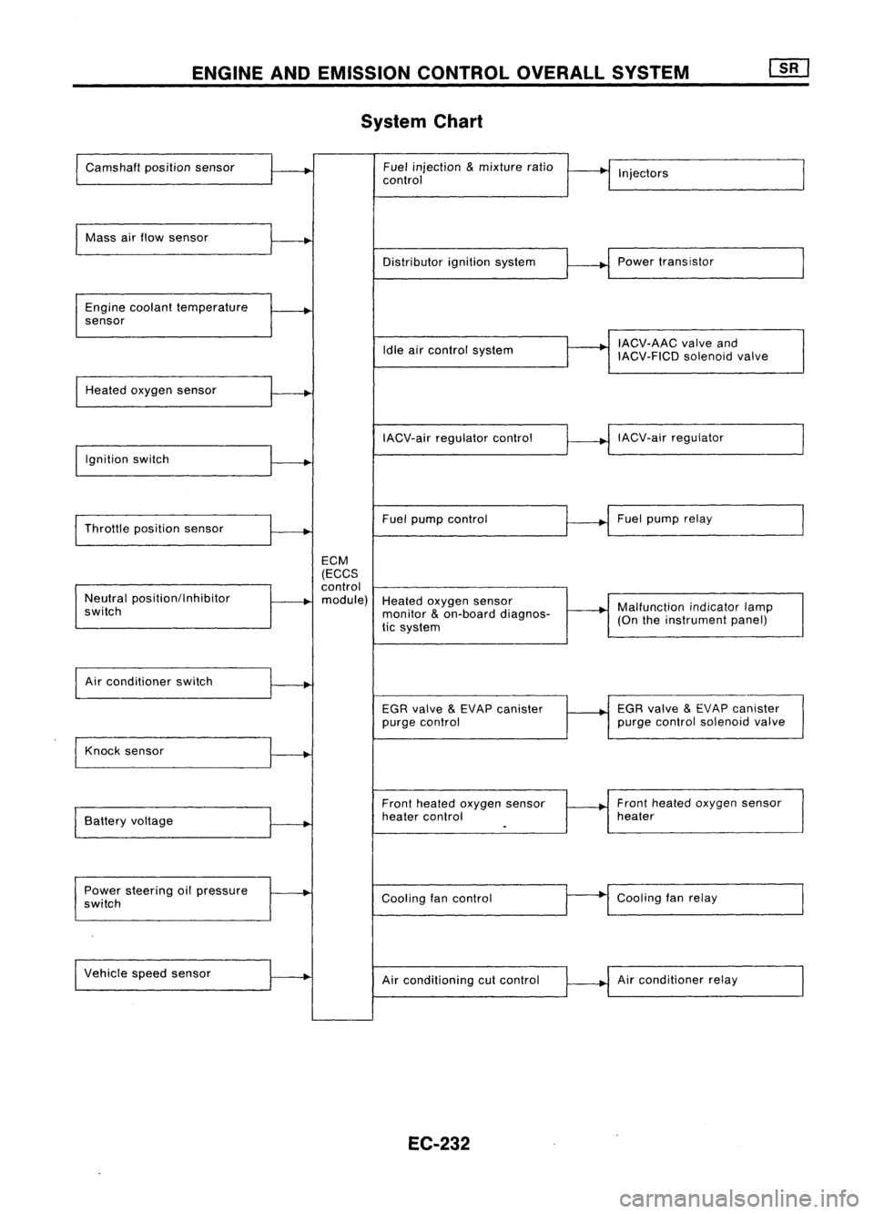
ENGINEANDEMISSION CONTROLOVERALLSYSTEM
System Chart
Camshaft positionsensor Fuel
injection
&
mixture ratio
•
I
I
control Injectors
Mass airflow sensor
I
Distributorignitionsystem
r
~1
Power transistor
Engine coolant temperature
.
sensor
I
IACV-AAC valveand
Idle aircontrol system
IACV-FICDsolenoidvalve
Heated oxygen sensor
I
IACV-airregulator control
~--..j
IACV-air regulator
I
Ignition switch
I
I
Throttle position sensor
~-+
Fuel
pump control Fuel
pump relay
ECM
(ECCS
control
Neutral position/Inhibitor
.
module) Heatedoxygen sensor
switch monitor
&
on-board diagnos-
~-+
Malfunction
indicatorlamp
tic system (On
theinstrument panel)
I
Air conditioner switch
t~
EGRvalve
&
EVAP canister
1---+
EGR
valve
&
EVAP canister
purge control purge
control solenoid valve
Knock sensor
.....
Frontheated oxygen sensor Front
heated oxygen sensor
Battery voltage
.
heater
control heater
I
.
Power steering oilpressure
~
Coolingfancontrol
--
Cooling
fanrelay
switch
Vehicle speedsensor
.....
Airconditioning cutcontrol Air
conditioner relay
EC-232
Page 962 of 1701

BASICSERVICE PROCEDURE
Idle Speedllgnition TiminglldleMixtureRatio
Adjustment
PREPARATION
• Make surethatthefollowing partsarein
good order.
(1) Battery
(2) Ignition system
(3) Engine oiland coolant levels
(4) Fuses
(5) ECM harness connector
(6) Vacuum hoses
(7) Airintake system
(Oil filler cap,oillevel gauge, etc.)
(8) Fuel pressure
(9) Engine compression
(10) Throttle valve
Overall inspection sequence
INSPECTION
•
•
•
•
•
•
On
models equipped withairconditioner,
checks shouldbecarried outwhile theair
conditioner is"OFF".
On models equipped withautomatic
transaxle, whenchecking idlespeed, ignition
timing andmixture ratio,checks shouldbe
carried outwhile shiftlever isin "N" position.
When measuring "CO"percentage, insert
probe morethan40cm (15.7 in)into tailpipe.
Turn offheadlamps, heaterblower, rear
defogger. Keep frontwheels pointed straight ahead.
Make thecheck afterthecooling fanhas
stopped.
•
Perform diagnostic testmode II
(Self-diagnostic results).
OK
Check
&
adjust ignition timing.
Check
&
adjust idlespeed.
Check heated oxygen sensor
function. NG
Repair orreplace.
NG Check heated oxygen sensor
harness. NG
Repair orreplace harness.
OK OK
Check CO%. OKReplace heatedoxygen sensor.
NG
INSPECTION END Check
emission controlparts
and repair orreplace ifneces-
sary.
EC-243
NG
Check heated oxygen sensor
function.
OK
Page 974 of 1701
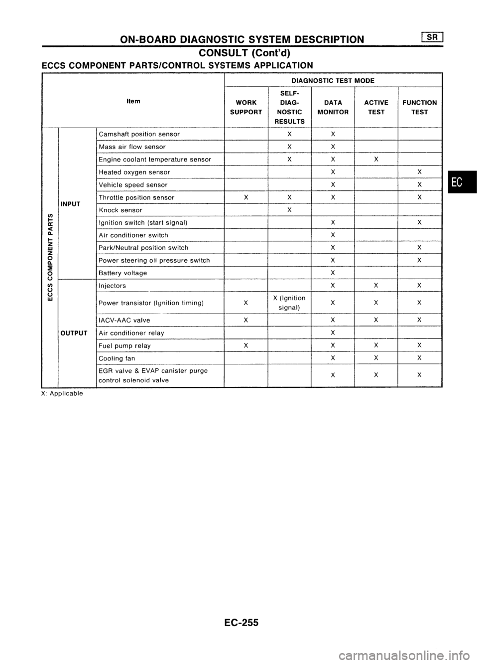
ON-BOARDDIAGNOSTIC SYSTEMDESCRIPTION
CONSULT (Coni'd)
ECCS COMPONENT PARTS/CONTROL SYSTEMSAPPLICATION
DIAGNOSTIC TESTMODE
SELF.
Item WORKDlAG.
DATAACTIVEFUNCTION
SUPPORT NOSTICMONITOR TESTTEST
RESULTS
Camshaft positionsensor XX
Mass airflow sensor XX
Engine coolant temperature sensor XX
X
Heated oxygen sensor X
X
Vehicle speedsensor X
X
Throttle positionsensor X
XX X
INPUT Knocksensor X
lJ)
~ Ignitionswitch(startsignal) X
X
a:
<
0-
Airconditioner switch X
~
z
Park/Neutralpositionswitch X
X
w
z
0
Powersteering oilpressure switch X
X
0-
:!
X
0
Battery
voltage
0
lJ)
Injectors XX
X
0
0
X(Ignition
w
Powertransistor (Iynitiontiming) X
XX
X
signal)
IACV-AAC valve XX
XX
OUTPUT Air
conditioner relay X
Fuel pump relay XXX
X
Cooling fan X
X
X
EGR valve
&
EVAP canister purge
X
X
X
control solenoid valve
X: Applicable
EC-255
•
Page 977 of 1701
![NISSAN ALMERA N15 1995 Service Manual ON-BOARDDIAGNOSTIC SYSTEMDESCRIPTION
CONSULT (Conl'd)
Monitored item ECM
Main
[Unit] input
signals Description
Remarks
signals
AIR COND SIG •Indicates [ON/OFF] conditionofthe
[ON/OFF]
00
air
NISSAN ALMERA N15 1995 Service Manual ON-BOARDDIAGNOSTIC SYSTEMDESCRIPTION
CONSULT (Conl'd)
Monitored item ECM
Main
[Unit] input
signals Description
Remarks
signals
AIR COND SIG •Indicates [ON/OFF] conditionofthe
[ON/OFF]
00
air](/manual-img/5/57349/w960_57349-976.png)
ON-BOARDDIAGNOSTIC SYSTEMDESCRIPTION
CONSULT (Conl'd)
Monitored item ECM
Main
[Unit] input
signals Description
Remarks
signals
AIR COND SIG •Indicates [ON/OFF] conditionofthe
[ON/OFF]
00
air
conditioner switchasdetermined
by the airconditioning signal.
PIN POSI SW
00
•
Indicates [ON/OFF] conditionfromthe
[ON/OFF] park/neutralpositionswitchsignal.
PW/ST SIGNAL •Indicates [ON/OFF] conditionofthe
[ON/OFF]
00
power
steering oilpressure switch
determined bythe power steering oil
pressure signal.
INJ PULSE [msec]
0
•
Indicates theactual fuelinjection •
When theengine isstopped, acertain
pulse widthcompensated byECM computedvalueisindicated.
according tothe input signals.
IGN TIMING [BTDC]
0
•
Indicates theignition timingcomputed
by ECM according tothe input sig-
nals.
IACV-AACIV
[%]
•Indicates theidle aircontrol valve
0
(AAC
valve) control valuecomputed
by ECM according tothe input sig-
nals.
A/F ALPHA [%J •Indicates themean valueofthe air- •When theengine isstopped, acertain
0
fuel
ratio feedback correction factor valueisindicated.
per cycle. •This dataalsoincludes thedata for
the air-fuel ratiolearning control.
AIR COND RLY •Indicates theairconditioner relay
[ON/OFF]
0
control
condition (determined byECM
according tothe input signal).
FUEL PUMP RLY •Indicates thefuel pump relaycontrol
[ON/OFFJ
0
condition
determined byECM accord-
ing tothe input signals.
COOLING FAN
•Indicates thecontrol condition ofthe
[HI/LOW/OFFJ coolingfans(determined byECM
0
according
tothe input signal).
HI ...High speed operation
LOW ...Low speed operation
OFF ...Stopped
EGRC SOLIV •Indicates thecontrol condition ofthe
[ON/OFFJ EGR
valve
&
EVAP canister Purge
control solenoid valve(determined by
0
ECM
according tothe input signal).
ON ...EGR andEVAP canister purge
operation cut-off
OFF ...EGR andEVAP canister purge
operation notcut-off
VOLTAGE •Voltage measured bythe voltage
[V] probe.
PULSE •Pulse width, frequency orduty cycle •Only "#"isdisplayed ifitem is
[msec] or[Hz] or
measuredbythe pulse probe. unabletobe measured.
[%]
•Figures with"#"s aretemporary
ones. Theyarethesame figures as
an actual pieceofdata which wasjust
previously measured.
EC-258
Page 980 of 1701
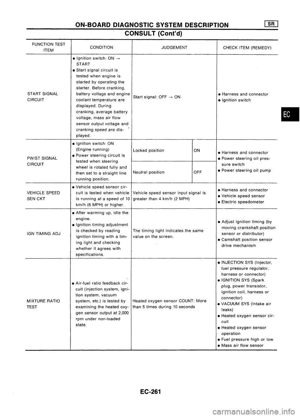
ON-BOARDDIAGNOSTIC SYSTEMDESCRIPTION
CONSULT (Cont'd)
FUNCTION TEST
CONDITION
ITEM JUDGEMENT
CHECKITEM(REMEDY)
• Ignition switch:ON
->
START
• Start signal circuit is
tested whenengine is
started byoperating the
starter. Beforecranking,
START SIGNAL batteryvoltage andengine
Startsignal: OFF
->
ON •
Harness andconnector
CIRCUIT coolanttemperature are
•Ignition switch
displayed. During
cranking, averagebattery
voltage, massairflow
sensor outputvoltage and
cranking speedaredis-
.
played .
• Ignition switch:ON
(Engine running)
Lockedposition ON
•Harness andconnector
PW/ST SIGNAL •
Power steering circuitis
•Power steering oilpres-
CIRCUIT tested
whensteering
sureswitch
wheel isrotated fullyand
•Power steering oilpump
then settoastraight lineNeutral
position OFF
running position.
• Vehicle speedsensor cir-
•Harness andconnector
VEHICLE SPEED cuitistested whenvehicle Vehiclespeedsensor inputsignal is
•Vehicle speedsensor
SEN CKT isrunning ataspeed of10 greater than4km/h (2MPH)
•Electric speedometer
km/h (6MPH) orhigher .
• After warming up,idle the
engine. •Adjust ignition timing(by
• Ignition timingadjustment
movingcrankshaft position
is checked byreading Thetiming lightindicates thesame
IGN TIMING ADJ
ignitiontimingwithatim- valueonthe screen. sensor
ordistributor)
ing light andchecking •
Camshaft positionsensor
whether itagrees with drive
mechanism
specifications. •INJECTION SYS(Injector,
fuel pressure regulator,
harness orconnector)
• Air-fuel ratiofeedback cir- •
IGNITION SYS(Spark
cuit (injection system,igni- plug,
power transistor,
ignition coil,harness or
tion system, vacuum
connector)
MIXTURE RATIO system,
etc.)istested byHeated oxygen sensorCOUNT: More
•VACUUM SYS(Intake air
TEST examining
theheated oxy-than
5times during 10seconds
leaks)
gen sensor outputat2,000
•Heated oxygen sensorcir-
rpm under non-loaded
cuit
state. •Heated oxygen sensor
operation
• Fuel pressure highorlow
• Mass airflow sensor
EC-261
•
Page 994 of 1701
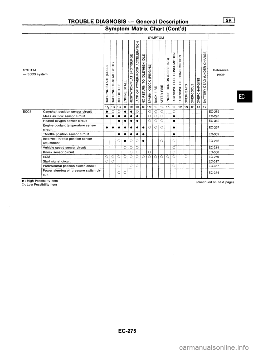
TROUBLEDIAGNOSIS -General Description
Symptom MatrixChart(Cont'd)
SYMPTOM
z
0
1=
0::
Z
W
w w
CJ
..J
W
0
Z
CJ
W
..J
1=
0
0::
0::
()
9
5
Q.
1=
::::>
()
z
:2
I
i='
en
I
5
::;
Q.
()
is'
0
;:::
CJ
::::>
:2
0::
~
0::
:r:
z
w
en
::::>
SYSTEM
..J
0
0
en
z
w
Reference
0
Q.
W
e;
w
en
0
- ECCS system
~
....
en
0
..J
Z
9-
0
z
Z
0::
Q.
9
a:
()
0
2-
page
....
....
ii:
..J
U
....
Z
CJ
0::
..J
W
0
W
..J
0
en
..J
u-
s:
.... ::.:::
0
::::>
0
z
W
..J
U
u-
e;
....
w
Z
0
z
0
w
z
(/)
en
w
en
0::
..J
....
Q.
W
::::>
w
w
....
..J
0::
0
0 0
9
en
0
0::
Z
0::0::
0::
>>
0
>-
~
u-
::::>::.:::
u:
enen
0
I
Z Z
W
0
....
u:
w
W
0::
2i 2i
I
Z
W
::.:::
0::
z
en
(/)
I
()
()
w
CJ
e;
....
::.:::
0:: 0::
::.:::
w w
W
0::
0::
0::
1=
0::
0::
::::>
en
()
()
....
e;
uu
w
w
w
0
Z
w
0
Q.
u-
Z
x x
> >>
I I
0::
W
I
..J
Z
(/)
1Il
w
w w
000
1Il
11\ 18
1C 1F
1H 1R
1S1M 1J1L1K
1T
1V1N 1P1X
1Y
ECCS Camshaft
positionsensorcircuit
•
0
0
••
0
000 0
EC-289
Mass airflow sensor circuit
•••
•••
0
00
•
EC-293
Heated oxygen sensorcircuit
••
••
0
00
•
EC-362
Engine coolant temperature sensor
••• ••
•
•
0
0
0
•
EC-297
circuit
Throttle positionsensorcircuit
••
••
• •
EC-309
Incorrect fhrottleposition sensor
0
•
0
0
•
0
0
EC-272
adjustment
Vehicle speedsensor circuit
000
0
EC-314
Knock sensor circuit
00
0 0
EC-306
ECM
0
0
0
0
00000
0
00 0
EC-270
Start signal circuit
00
EC-317
Park/Neutral positionswitchcircuit
000
0
EC-357
Power steering oilpressure switchcir-
0
0
EC-354
cuit
•
• ;High Possibility Item
0;
Low Possibility Item
EC-275
(continued
onnext page)
Page 1003 of 1701
![NISSAN ALMERA N15 1995 Service Manual TROUBLEDIAGNOSIS -General Description
[]:KJ
ECM Terminals andReference Value(Cont'd)
*Data arereference values.
TERMINAL WIRE
ITEM CONDITION *
DATA
NO. COLOR
/Ignitionswitch"ON'"
t NISSAN ALMERA N15 1995 Service Manual TROUBLEDIAGNOSIS -General Description
[]:KJ
ECM Terminals andReference Value(Cont'd)
*Data arereference values.
TERMINAL WIRE
ITEM CONDITION *
DATA
NO. COLOR
/Ignitionswitch"ON'"
t](/manual-img/5/57349/w960_57349-1002.png)
TROUBLEDIAGNOSIS -General Description
[]:KJ
ECM Terminals andReference Value(Cont'd)
*Data arereference values.
TERMINAL WIRE
ITEM CONDITION *
DATA
NO. COLOR
/Ignitionswitch"ON'"
t
"N" or"P" position
(A/T)
OV
35
G/OR
Neutral
position
Neutralposition
(M/T)
switch/lnhibitor switch
I'gnitionswitch"ON"I
BATTERYVOLTAGE
L
Except theabove gearposition (11
-14V)
I'gnition switch"OFF"I
OV
36 B/R Ignition
switch
Ilgnitionswitch"ON"I BATTERY
VOLTAGE
(11 -14V)
37 P/L Throttle
position sen-
pgnition switch"ON"I
Approximately5V
sor power supply
38 Powersupply forECM
Ilgnition switch"ON"I BATTERY
VOLTAGE
47 W/R
(11-14V)
39 B ECCSground IEngine
isrunning.1
Engineground
L
Idle speed
IEngine isrunning.!
L
Both airconditioner switchandblower fanApproximately
OV
41 G Air
conditioner switch switch
are"ON".
IEngine isrunning.1
BATTERYVOLTAGE
L
Airconditioner switchis"OFF". (11
-14V)
IEngine isrunning.1
OV
Power steering oil
L
Steering wheelisbeing turned.
43 PUlW
pressureswitch
IEngineisrunning.1
L
Steering wheelisnot being turned. 7
-9V
46 W/L Power
supply
I'gnitionswitch
"0FFj
BATTERY
VOLTAGE
(Back-up) (11-14V)
48 B ECCSground IEngine
isrunning.1
Engineground
L
Idle speed
109 W/L Currentreturn
Ilgnitionswitch"OFF"I BATTERY
VOLTAGE
(11 -14V)
101 RIB InjectorNo.1
103
G/B
InjectorNo.3
BATTERYVOLTAGE
110 Y/B InjectorNO.2 IEngine
isrunning.1
(11-14V)
112 LIB InjectorNO.4
EC-284