Page 1136 of 1701
SERVICEDATAANDSPECIFICATIONS (SOS)
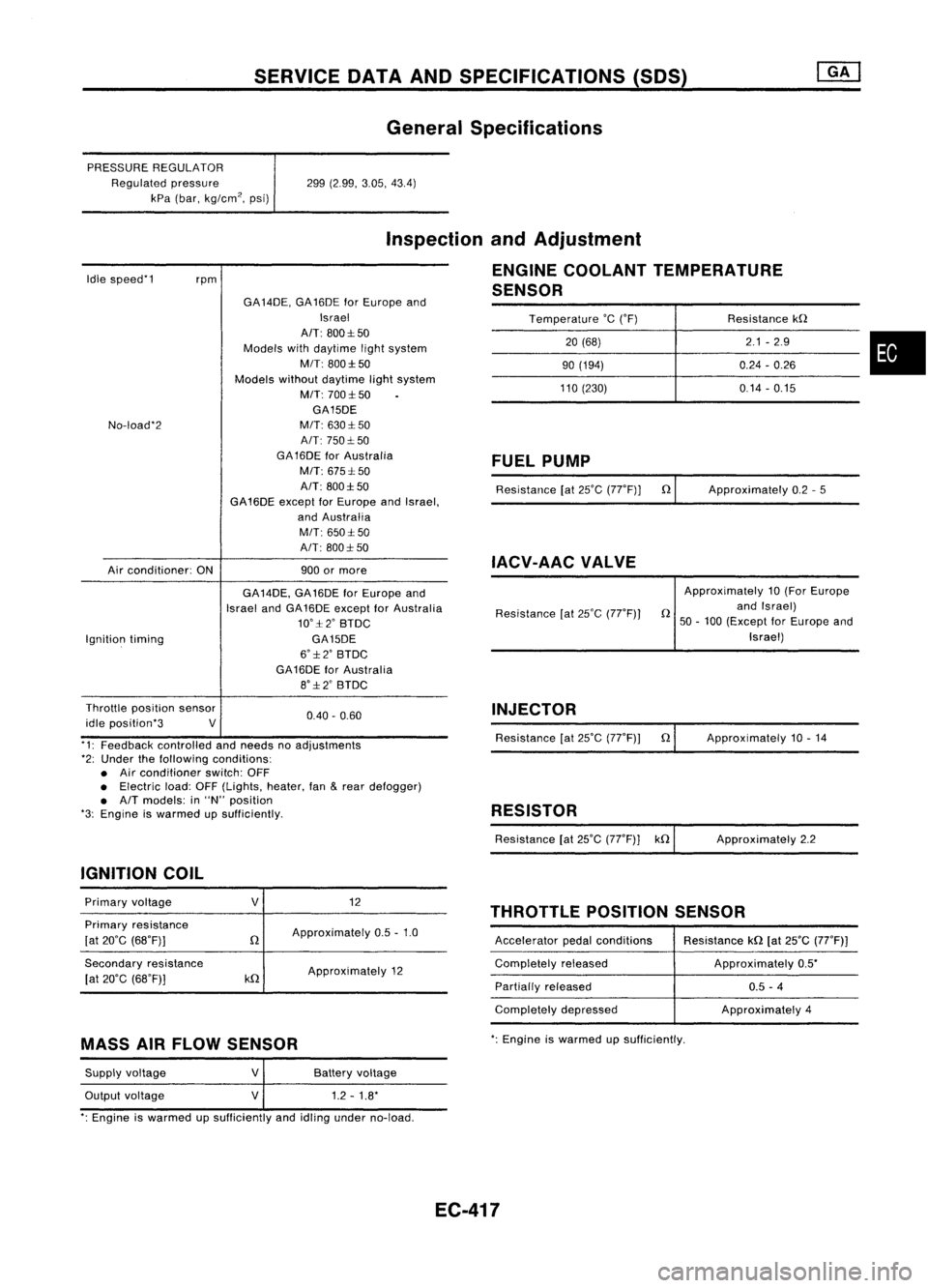
General Specifications
PRESSURE REGULATOR
Regulated pressure
kPa (bar, kg/cm
2,
psi) 299
(2.99, 3.05,43.4)
Idle speed'1
rpm
Inspection
andAdjustment
ENGINE COOLANT TEMPERATURE
SENSOR
Temperature
'c
('F) Resistancekn
20 (68) 2.1
-2.9
•
90
(194) 0.24-0.26
110 (230) 0.14-0.15
No-load'2
Air conditioner: ONGA
14DE, GA16DE forEurope and
Israel
AIT: 800:1:50
Models withdaytime lightsystem
MIT: 800:1:50
Models withoutdaytime lightsystem
M/T: 700:1:50
GA15DE
M/T: 630:1: 50
A/T: 750:1: 50
GA 16DE forAustralia
M/T: 675:1: 50
A/T: 800:1:50
GA16DE exceptforEurope andIsrael,
and Australia
M/T: 650:1:50
A/T: 800:1: 50
900 ormore
FUEL
PUMP
Resistance [at25'C (77'F)] n
IACV-AAC VALVE
Approximately
0.2-5
Ignition timing GA
14DE, GA16DE forEurope and
Israel andGA16DE except forAustralia
10':1:2' BTDC
GA15DE
6':1:2' BTDC
GA16DE forAustralia
8':1:2' BTDC Resistance
[at25'C (77'F)) Approximately
10(For Europe
n andIsrael)
50 -100 (Except forEurope and
Israel)
0.40. 0.60
Throttle
position sensor
idle position'3 V
'1: Feedback controlled andneeds noadjustments
'2: Under thefollowing conditions:
• Air conditioner switch:OFF
• Electric load:OFF(Lights, heater,fan
&
rear defogger)
• A/T models: in"N" position
'3: Engine iswarmed upSUfficiently.
IGNITION COIL INJECTOR
Resistance [at25'C (77'F)) n
RESISTOR
Resistance [at25'C (77'F)] kn Approximately
10.14
Approximately 2.2
THROTTLE POSITIONSENSOR
Primary
voltage
Primary resistance
[at 20'C (68'F)]
Secondary resistance
[at 20'C (68'F)]
V
n
kn
12
Approximately 0.5-1.0
Approximately 12 Accelerator
pedalconditions
Completely released
Partially released
Completely depressed Resistance
kn[at25'C (77'F))
Approximately 0.5'
0.5 -4
Approximately 4
MASS AIRFLOW SENSOR
':
Engine iswarmed upsufficiently.
Supply voltage
Output voltage
V
V
Battery
voltage
1.2 -1.8'
': Engine iswarmed upSUfficiently andidling under no-load.
EC-417
Page 1137 of 1701
SERVICEDATAANDSPECIFICATIONS (SOS)
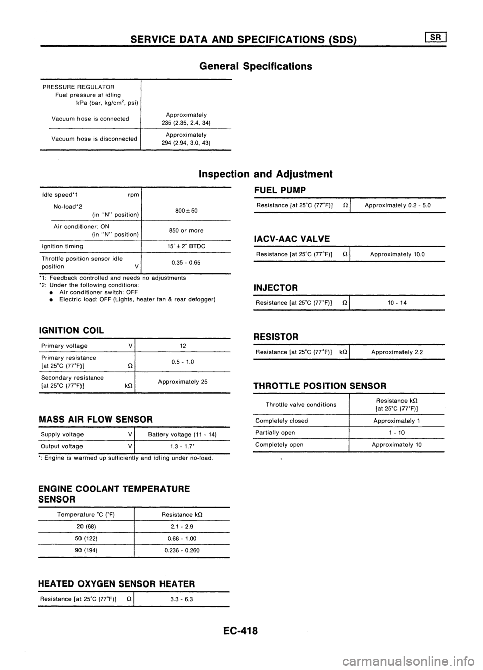
General Specifications
PRESSURE REGULATOR
Fuel pressure atidling
kPa (bar, kg/cm
2,
psi)
Vacuum hoseisconnected
Vacuum hoseisdisconnected Approximately
235 (2.35. 2.4.34)
Approxi mately
294 (2.94, 3.0,43)
Idle speed'1
No-load'2 rpm
(in "N" position) 800:1:50
Inspection
andAdjustment
FUEL PUMP
Resistance [at25'C (77'F)] n
Approximately 0.2-5.0
Air conditioner: ON
(in "N" position)
Ignition timing
Throttle position sensoridle
position V850
ormore
IACV-AACVALVE
15':1:2' BTDC
Resistance[at25'C (77'F)] n
0.35 -0.65 Approximately
10.0
'1: Feedback controlled andneeds noadjustments
'2: Under thefollowing conditions:
• Air conditioner switch:OFF
• Electric load:OFF(Lights, heaterfan
&
rear defogger)
IGNITION COIL INJECTOR
Resistance [at25'C (77'F)) n'
1_0_-_1_4 _
RESISTOR
Primary voltage
Primary resistance
[at 25'C (77'F))
V
12
0.5 -1.0 Resistance
[at25'C (77'F)) kn ApproXimately 2.2
Secondary resistance
[at 25'C (77'F))
kn
Approximately
25
THROTTLEPOSITIONSENSOR
MASS AIRFLOW SENSOR
Supply voltage
Output voltage
V
V
Battery
voltage (11-14)
1.3 -1.7'
Throttle
valveconditions
Completely closed
Partially open
Completely open Resistance
kn
[at 25'C (77'F)]
Approximately 1
1 - 10
Approximately 10
': Engine iswarmed upsufficiently andidling under no-load.
ENGINE COOLANT TEMPERATURE
SENSOR
Temperature
'c
('F)
20 (68)
50 (122)
90 (194) Resistance
kn
2.1-2.9
0.68 -1.00
0.236 -0.260
HEATED OXYGEN SENSOR HEATER
Resistance [at25'C (77'F)] n
I
3.3-6.3
EC-418
Page 1178 of 1701
Oilpressure checkSERVICE
DATAANDSPECIFICATIONS (50S)
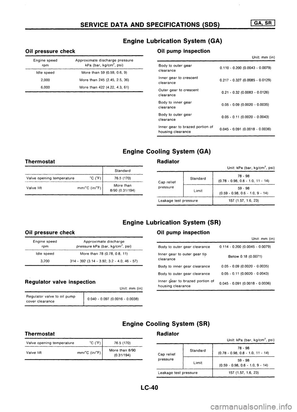
Engine Lubrication System(GA)
Oil pump inspection
I
GA, SR
I
Engine speed
rpm
Idle speed
2,000
6,000
Approximate
dischargepressure
kPa (bar, kg/cm?, psi)
More than
59(0.59, 0.6,9)
More than
245(2.45, 2.5,36)
More than
422(4,22, 4.3,61)
Body
toouter gear
clearance
Inner geartocrescent
clearance
Outer geartocrescent
clearance
Body toinner gear
clearance
Body toouter gear
clearance
Inner geartobrazed portionof
housing clearance Unit:
mm(in)
0.110 -0.200 (0.0043 -0.0079)
0.217 -0.327 (0.0085 -0.0129)
0.21 -0.32 (0.0083 -0.0126)
0.05 -0.09 (0.0020 -0.0035)
0.05 -0 11 (0.0020 -0.0043)
0.045 -0.091 (0.0018 -0.0036)
Thermostat Engine
Cooling System(GA)
Radiator
Standard Unit:
kPa(bar, kg/cm?, psi)
Valve opening temperature °C("F)
Valve lift mml'C(inI'F)
76.5
(170)
More than
8/90 (0.31/194)
Standard
Cap relief
pressure Limit
Leakage testpressure
78
-98
(0.78 -0.98, 0.8-10, 11-14)
59 -98
(059 -0.98, 06-10, 9-14)
157 (1.57, 16,23)
Oil pressure check Engine
Lubrication System(SR)
Oil pump inspection
Engine speed
rpm
Idle speed
3,200
Approximate
discharge
pressure kPa(bar,
kg/cm?,
psi)
More than
78(0.78, 0.8,11)
314 -392 (3.14 -3.92, 3.2-4.0, 46-57)
Body
toouter gearclearance
Inner geartoouter geartip
clearance . Unit:
mm(in)
0,114 -0,200 (0.0045 -0.0079)
Below
0.18(0.0071)
Regulator valveinspection
Unit:mm(in) Body
toinner gearclearance
Body toouter gearclearance
Inner g-eartobrazed portionof
housing clearance
0.05
-0.09 (0.0020 -0.0035)
0.05 -0.11 (0.0020 -0,0043)
0.045 -0,091 (0,0018 -0,0036)
Regulator valvetooil pump
cover clearance
Thermostat 0040
-0097 (0,0016 -0.0038)
Engine Cooling System(SR)
Radiator
Valve opening temperature
Valve lift
°C
(OF)
mml"C
(inI"F)
765
(170)
More than
8/90
(0,31/194)
Standard
Cap relief
pressure Limit
Leakage testpressure
LC-40
Unit:
kPa(bar, kg/em?, psi)
78 -98
(0.78 -0,98, 0.8-1,0, 11-14)
59 -98
(0,59 -0.98, 0.6-1.0, 9-14)
157 (1.57, 1.6,23)
Page 1179 of 1701
SERVICEOATAAND SPECIFICATIONS (SOS)
Oil pressure check Engine
Lubrication System
Oil pump inspection
Unit:mm(in)
Body toouter gearclearance 0.12-0.20 (0.0047 -0.0079)
Outer geartoinner gearclearance Lessthan0.18(0.0071)
Engine
rpm
Idle speed
2,000 Approximate
dischargepressure
kPa (bar, kg/cm
2,
psi)
More than59(0.59, 0.6,9)
294 (2.9, 3,43) Housing
toinner gearclearance
Housing toouter gearclearance
Inner geartohousing clearance 0.05
-0.09 (0.0020 -0.0035)
0.05 -0.11 (0.0020 -0.0043)
0.05 -0.09 (0.0020 -0.0035)
•
Thermostat Engine
Cooling System
Radiator
Unit:kPa(bar, kg/cm
2,
psi)
Leakage testpressure
Valve
opening temperature
°c
(OF)
Valve lift
mmrC
(inrF)
88
(190)
More than10/100 (0.39/212) Cap
relief
pressure
LC-41
Standard
Limit 78
-98 (0.78 -0.98, 0.8-1.0,11 -14)
59 -98 (0.59 -0.98, 06-1.0, 9-14)
157 (1.57,1.6,23)
Page 1227 of 1701
CYLINDERBLOCK
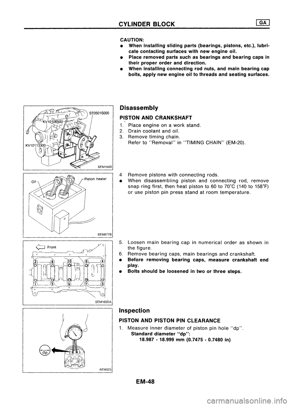
CAUTION:
• When installing slidingparts(bearings, pistons,etc.),lubri-
cate contacting surfaceswithnewengine oil.
• Place removed partssuchasbearings andbearing capsin
their proper orderanddirection.
• When installing connecting rodnuts, andmain bearing cap
bolts, apply newengine oiltothreads andseating surfaces.
Disassembly
PISTON ANDCRANKSHAFT
1. Place engine onawork stand.
2. Drain coolant andoil.
3. Remove timingchain.
Refer to"Removal" in"TIMING CHAIN"(EM-20).
4 Remove pistonswithconnecting rods.
• When disassembling pistonandconnecting rod,remove
snap ringfirst, thenheat piston to60 to70°C (140to158°F)
or use piston pinpress stand atroom temperature.
5. Loosen mainbearing capinnumerical orderasshown in
the figure.
6. Remove bearingcaps,mainbearings andcrankshaft.
• Before removing bearingcaps,measure crankshaft end
play.
• Bolts should beloosened intwo orthree steps.
AEM023 Inspection
PISTON ANDPISTON PINCLEARANCE
1. Measure innerdiameter ofpiston pinhole "dp".
Standard diameter
"dp":
18.987 -18.999
mm
(0.7475 -0.7480
in)
EM-48
Page 1238 of 1701
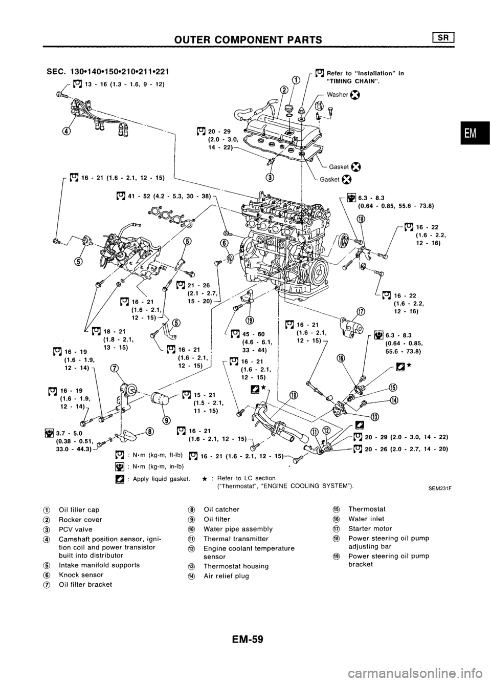
OUTERCOMPONENT PARTS
•
SEM231F
SEC.
130-140-150-210-211-221
~ __to:J
13•16 (1.3 -1.6, 9.12)
to:J
16•21 (1.6. 2.1,12. 15)
to:J
20•29
(2.0 •3.0,
14 .22)
to:J
41-52 (4.2 -5.3, 30-38)
~---- D_?
. 'J ~
~~~ 0
-t::;-.....~ /,
0
to:J
21-26 ./"
(2.1. 2.7, ,./"~/'
12 -1~)
fs\
19-~~7
~ to:J
16•21
Q
to:J
18. 21 ,
to:J
45_60 (1.6-2.1, 0
Ii]
6.3 _8.3
(1.8 •2.1, (4.6•6.1, 12•15)
1
(0.64•0.85,
to:J
16•19 13-15)
to:J
16•21 33•44)
(1.6 -1.9, (1.6-2.1,
to:J
16•21
12 -14)
12•15)
t"J
16•,.
f"-~
t"J
15•21
r::!
*
H
...----4lJ
~~'. '1~
J
r \~ ~~'..,:;
1,
~Q.
/¥i-;:
--'Il
1il3.7 -5.0
J~
--A)
to:J
16-21
~11V>/
(0.38 _0.51, A~ - (1.6.2.1,12•15)\...,//
~to:J
20.29(2.0-3.0, 14-22)
33.0 •44.3)
Y
&'/-
:f~l
to:J
20•26 (2.0 •2.7, 14-20)
to:J :
N'm (kg-m, fl-Ib)
to:J
16-21 (1.6 -2.1, 12-15)~/
Ii] :
N'm (kg-m, in-Ib) •
~ :Apply
liquidgasket.
*:
Refer toLC section
("Thermostat", "ENGINECOOLING SYSTEM").
G)
Oilfiller cap
@
Oilcatcher
@
Thermostat
@
Rocker cover
@
Oilfilter
@
Water inlet
@
PCVvalve
@
Water pipeassembly
@
Starter motor
@
Camshaft
positionsensor,igni-
@
Thermal transmitter
@
Power steering oilpump
tion coiland power transistor
@
Engine coolant temperature adjusting
bar
built intodistributor
sensor
@
Power
steering oilpump
@
Intake manifold supports
@
Thermostat housing bracket
@
Knock sensor
@
Airrelief plug
rJ)
Oilfilter bracket
EM-59
Page 1281 of 1701
SEM141FA
jPiSIOn healer
SEM877S CYLINDER
BLOCK
CAUTION:
• When installing slidingparts(bearings, pistons,etc.),apply
new engine oiltothe sliding surfaces.
• Place removed partssuchasbearings andbearing capsin
their proper orderanddirection.
• Apply newengine oiltobolt thread andseat surfaces when
tightening thefollowing: Connecting rodbolts andmain
bearing capbolts.
• Donot allow anymagnetic materials tocontact thering gear
teeth offlywheel/drive plate.
Disassembly
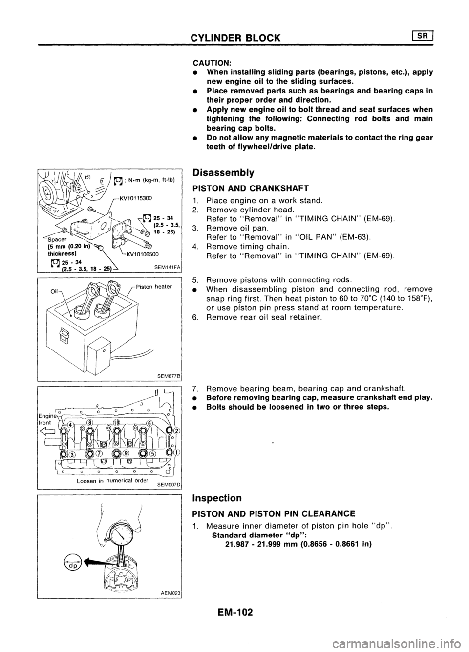
PISTON ANDCRANKSHAFT
1. Place engine onawork stand.
2. Remove cylinder head.
Refer to"Removal" in"TIMING CHAIN"(EM-69).
3. Remove oilpan.
Refer to"Removal" in"OIL PAN" (EM-63).
4. Remove timingchain.
Refer to"Removal" in"TIMING CHAIN"(EM-69).
5. Remove pistonswithconnecting rods.
• When disassembling pistonandconnecting rod,remove
snap ringfirst. Then heatpiston to60 to70°C (140to158°F),
or use piston pinpress stand atroom temperature.
6. Remove rearoilseal retainer.
7. Remove bearingbeam,bearing capand crankshaft.
• Before removing bearingcap,measure crankshaft endplay.
• Bolts should beloosened intwo orthree steps.
Loosen innumerical order.
SEM007D
AEM023
Inspection
PISTON ANDPISTON PINCLEARANCE
1. Measure innerdiameter ofpiston pinhole "dp".
Standard diameter"dp":
21.987 -21.999
mm
(0.8656 -0.8661
in)
EM-102
Page 1323 of 1701
Unit:mm(in) 183.0(7.205)
SEM707DCYLINDER
BLOCK
Preparation
• Drill ahole intotheattachment (KV10108101).
Disassembly
PISTON ANDCRANKSHAFT
1. Place engine onawork stand.
2. Drain coolant andoil.
3. Remove timingbelt.
4. Remove waterpump.
5. Remove oilpan andoilpump.
6. Remove cylinder head.
7. Remove pistonswithconnecting rods.
When disassembling pistonandconnecting rod,heat piston to
60 to70°C (140to158°F) oruse piston pinpress standatroom
temperature.
Heater
SEM360D
8.Remove bearingcapand crankshaft.
Place thebearings andcaps intheir proper order.
Upper bearings (cylinderblockside)haveoilgroove.
Loosen innumerical order.
SEM564A
SEM291
9.
Remove pistonringswithatool.
EM-144