Page 342 of 1701
TROUBLEDIAGNOSES
c(
C/UNIT CONNECTOR
5 .6 25. 26
,33 .34 5354,
(;) ASSactuator
a-pin connector
(ASS actuator side)
P
ASS relay box
2-pin connector
(ASS actuator side)
rO-...@
U!l.LJ
SBR245D
~i8
ASS relay box
2-pin connector
(ASS actuator side)
rO-...@
U!l.LJ
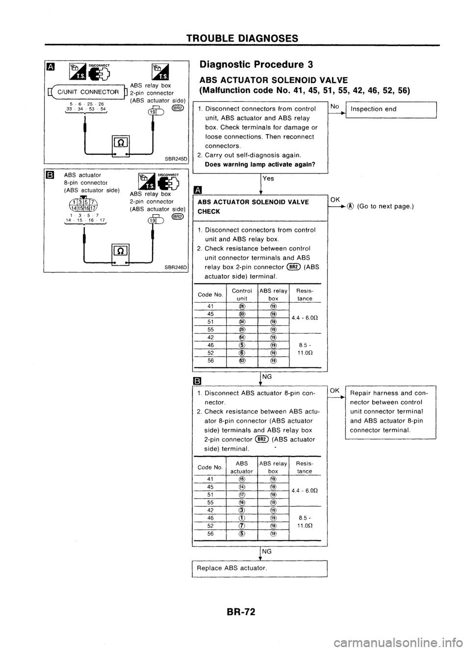
SBR246D Diagnostic
Procedure3
ABS ACTUATOR SOLENOIDVALVE
(Malfunction codeNo.41,45,51, 55,42, 46,52,56)
1. Disconnect connectorsfromcontrol
~Inspection end
unit, ASS actuator andASS relay
box. Check terminals fordamage or
loose connections. Thenreconnect
connectors.
2. Carry outself-diagnosis again.
Does warning lampactivate again?
Yes
m
ABS ACTUATOR SOLENOIDVALVE OK
CHECK
f---+@
(Gotonext page.)
1. Disconnect connectors fromcontrol
unit and ABS relay box.
2. Check resistance betweencontrol
unit connector terminalsandASS
relay box2-pin connector
@
(ABS
actuator side)terminal.
Code No. Control
ASSrelay Resis-
unit boxtance
41
@
@
45
@
@
4.4-6.0n
51
@
@
55
@
@
42
@
@
46
CID
@
85-
52 @ @110n
56
@
@
(;)
NG
1. Disconnect ASSactuator 8-pincon- OK
Repair harness andcon-
nector. ~
nectorbetween control
2. Check
resistance betweenABSactu- unitconnector terminal
ator 8-pin connector (ABSactuator and
ASS actuator 8-pin
side) terminals andASS relay box connector
terminal.
2-pin connector
@)
(ABS actuator
side) terminal.
.
Code No. ASS
ASS
relay Resis-
actuator box
tance
41
@
@
45
@
@)
4.4-6.0n
51
@
@
I
55
@
@
42
@)
@
46
CD
@
85-
52 (J)
@11.0n
56
CID
@
NG
Replace ABSactuator.
BR-72
Page 344 of 1701
TROUBLEDIAGNOSES
~i5
E(
C/UNITCONNECTOR
P
,14.9.11 .12, ,15.10.38.13,
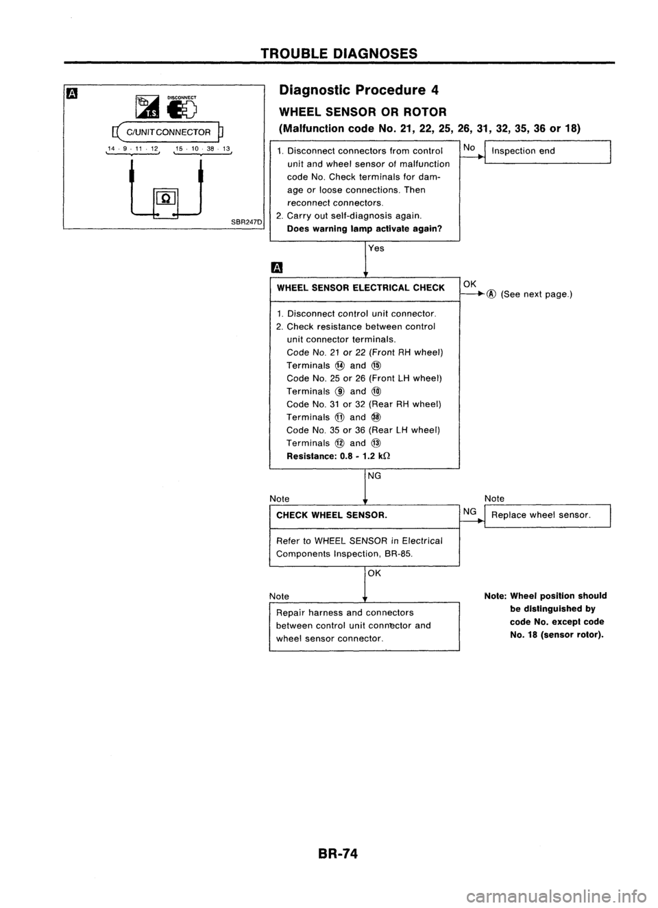
SBR247DDiagnostic
Procedure4
WHEEL SENSOR ORROTOR
(Malfunction codeNo.21,22,25,26,31, 32,35, 36or18)
1. Disconnect connectors fromcontrol
~Inspection end
I
unit and wheel sensor ofmalfunction
code No.Check terminals fordam-
age orloose connections. Then
reconnect connectors.
2. Carry outself-diagnosis again.
Does warning lampactivate again?
Yes
m
WHEEL SENSOR ELECTRICAL CHECK
OK
~@
(Seenextpage.)
1. Disconnect controlunitconnector.
2. Check resistance betweencontrol
unit connector terminals.
Code No.21or22 (Front RHwheel)
Terminals
@
and @
Code No.25or26 (Front LHwheel)
Terminals
@
and
@
Code No.31or32 (Rear RHwheel)
Terminals
@
and
@
Code No.35or36 (Rear LHwheel)
Terminals
@
and
@
Resistance: 0.8•1.2 kD
NG
Note Note
CHECK WHEELSENSOR.
~Replace wheelsensor.
I
Refer toWHEEL SENSOR inElectrical
Components Inspection,SR-85.
OK
Note
Note:
Wheel position should
Repair harness andconnectors
be
distinguished by
between controlunitconn'ector and
code
No.
exceplcode
wheel sensor connector.
No.
18(sensor rotor).
BR-74
Page 346 of 1701
m
ASS relay box2-pin
[it
DISCONNECT
connector
@
IJIJ
~c:\
(body side)
";V
rn
TROUBLE
DIAGNOSES
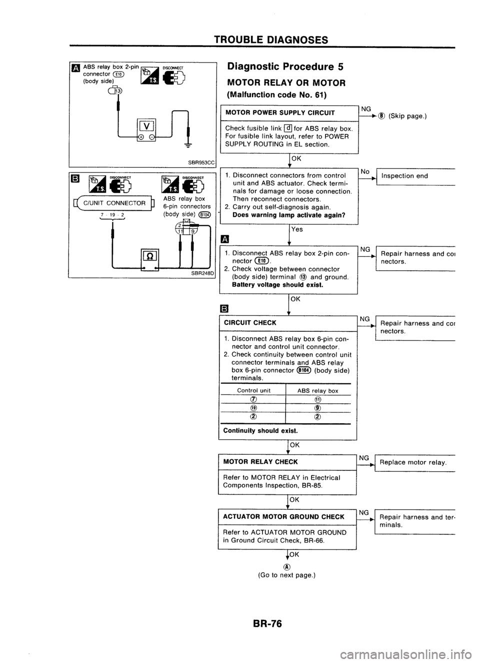
Diagnostic Procedure5
MOTOR RELAYORMOTOR
(Malfunction codeNo.61)
MOTOR POWERSUPPLY CIRCUIT
Check fusible link
@]
for ABS relay box.
For fusible linklayout, refertoPOWER
SUPPLY ROUTING inEL section.
NG
@
(Skip page.)
~iv
c(
C/UNIT CONNECTOR
P
7 19. 2
,
SBR953CC
~iV
ASS relay box
6-pin connectors
(body side)
@29
~
SBR248D OK
1. Disconnect connectors fromcontrol
unit and ABS actuator. Checktermi-
nals fordamage orloose connection.
Then reconnect connectors.
2. Carry outself-diagnosis again.
Does warning lampactivate again?
Yes
1. Disconnect ABSrelay box2-pin con-
nector@.
2. Check voltage between connector
(body side)terminal
@
and ground.
Battery voltage shouldexist.
CIRCUIT CHECK
1. Disconnect ABSrelay box6-pin con-
nector andcontrol unitconnector.
2. Check continuity betweencontrolunit
connector terminalsandABS relay
box 6-pin connector ~(body side)
terminals.
No
NG
NG
Inspection
end
Repair harness and
COI
nectors.
Repair harness andcor
nectors.
Control unit
Continuity shouldexist.
ASS
relay box
@
@
cID
OK
MOTOR RELAYCHECK
Refer toMOTOR RELAYinElectrical
Components Inspection,BR-8S.
OK
ACTUATOR MOTORGROUND CHECK
Refer toACTUATOR MOTORGROUND
in Ground CircuitCheck, BR-66.
OK
@
(Go tonext page.)
BR-76 NG
NG
Replace
motorrelay.
Repair harness andter-
minals.
Page 349 of 1701
Fa
ASS relay box2-pin
DISCONNECT
connector
@~~~
(body side)
I..lI&I
~V
ctD
TROUBLE
DIAGNOSES
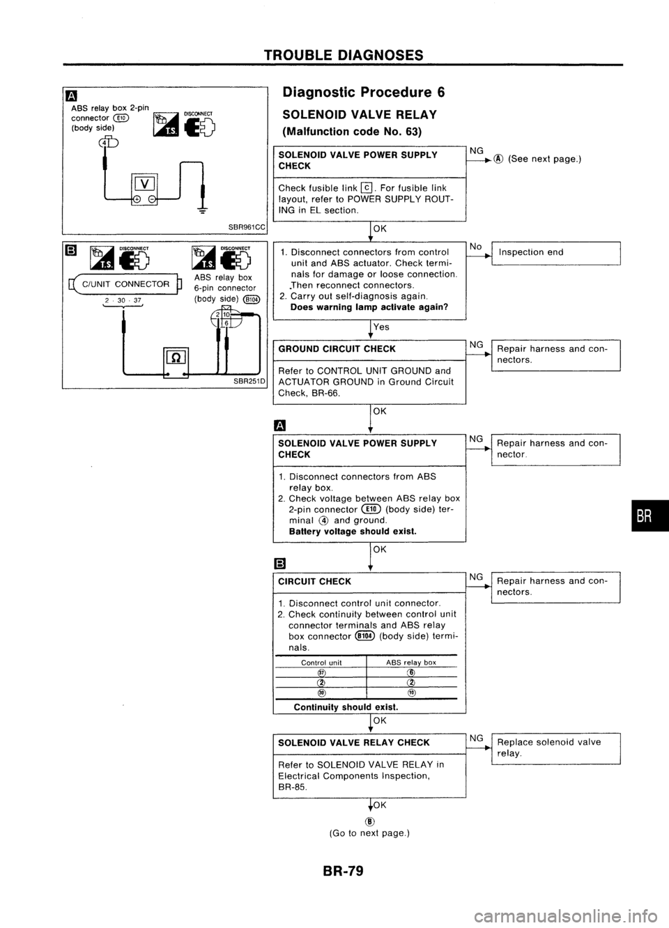
Diagnostic Procedure6
SOLENOID VALVERELAY
(Malfunction codeNo.63)
SOLENOID VALVEPOWER SUPPLY
CHECK
Check fusible link
@].
Forfusible link
layout, refertoPOWER SUPPLY ROUT-
ING inEL section.
NG
@
(See nextpage.)
~Io
( C/UNIT CONNECTOR
P
2 .30 .37
.
SBR961CC
ASS relay box
6-pin connector
(body side)
@W
Efe
OK
1. Disconnect connectors fromcontrol
unit andASS actuator. Checktermi-
nals fordamage orloose connection.
.Then reconnect connectors.
2. Carry outself-diagnosis again.
Does warning lampactivate again?
Yes
No
Inspection end
GROUND CIRCUITCHECK
Refer toCONTROL UNITGROUND and
SBR251D
ACTUATOR GROUNDinGround Circuit
Check, SR-66.
OK
SOLENOID VALVEPOWER SUPPLY
CHECK
1. Disconnect connectors fromASS
relay box.
2. Check voltage between ASSrelay box
2-pin connector
@
(body side)ter-
minal
@
and ground.
Battery voltage shouldexist.
CIRCUIT CHECK
1. Disconnect controlunitconnector.
2. Check continuity betweencontrolunit
connector terminalsandASS relay
box connector
@ill
(body side)termi-
nals. Repair
harness andcon-
nectors.
Repair harness andcon-
nector.
Repair harness andcon-
nectors.
•
Control unit
3T
ABS
relay box
Xi
@ @
Continuity shouldexist.
OK
SOLENOID VALVERELAY CHECK
Refer toSOLENOID VALVERELAY in
Electrical Components Inspection,
SR-85.
OK
@
(Go tonext page.)
BR-79
Replace
solenoid valve
relay.
Page 351 of 1701
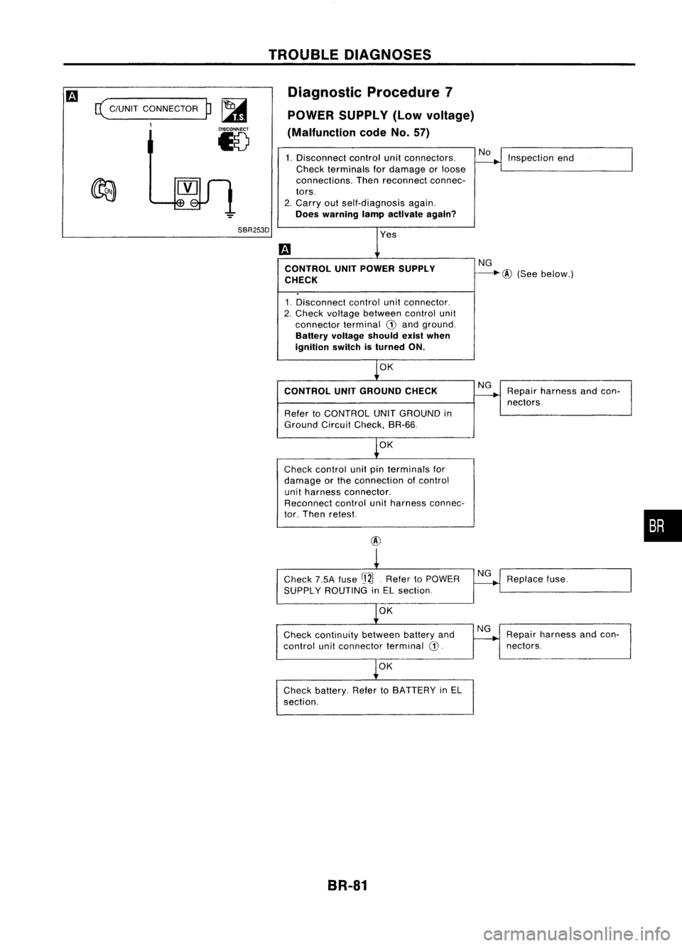
c(
C/UNIT CONNECTOR
1
p~
18
TROUBLE
DIAGNOSES
Diagnostic Procedure7
POWER SUPPLY (Lowvoltage)
(Malfunction codeNo.57)
1. Disconnect controlunitconnectors.
Check terminals fordamage orloose
connections. Thenreconnect connec-
tors.
2. Carry outself-diagnosis again.
Does warning lampactivate again? No
Inspection end
SBR253D CONTROL UNITPOWER SUPPLY
CHECK
1. Disconnect controlunitconnector.
2. Check voltage between controlunit
connector terminalG)and ground.
Battery voltage shouldexistwhen
ignition switchisturned ON.
OK NG
---.-.@
(Seebelow.)
CONTROL UNITGROUND CHECK
Refer toCONTROL UNITGROUND in
Ground CircuitCheck, BR-66.
OK
Check control unitpinterminals for
damage orthe connection ofcontrol
unit harness connector.
Reconnect controlunitharness connec-
tor. Then retest.
@
Check 7.5Afuse
rj2J.
Refer toPOWER
SUPPLY ROUTING inEL section.
OK
Check continuity betweenbatteryand
control unitconnector terminal
CD.
OK
Check battery. RefertoBATTERY inEL
section.
BR-81 NG
NG
NG Repair
harness andcon-
nectors.
Replace fuse.
Repa;, hame" aodcoo-
I
nectors.
•
Page 352 of 1701
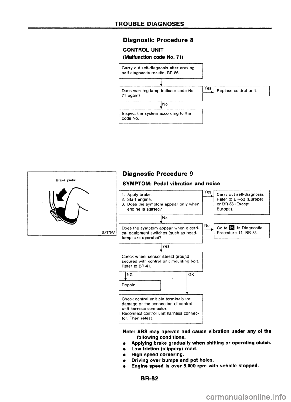
TROUBLEDIAGNOSES
Diagnostic Procedure8
CONTROL UNIT
(Malfunction codeNo.71)
Carry outself-diagnosis aftererasing
self-diagnostic results,BR-56.
Does warning lampindicate codeNo.
71 again?
No
Inspect thesystem according tothe
code No. Yes
Replace controlunit.
Brake pedal Diagnostic
Procedure9
SYMPTOM: Pedalvibration andnoise
No
Does thesymptom appearwhenelectri-
SAT797A
calequipment switches(suchashead-
lamp) areoperated?
1.
Apply brake.
2. Start engine.
3. Does thesymptom appearonlywhen
engine isstarted?
No
Yes
Check wheelsensor shieldgrou.nd
secured withcontrol unitmounting bolt.
Refer toBR-41. Yes
Carryoutself-diagnosis.
Refer toBR-53 (Europe)
or BR-56 (Except
Europe).
Go to
Ii1
inDiagnostic
Procedure 11,BR-83.
OK
Check control unitpinterminals for
damage orthe connection ofcontrol
unit harness connector.
Reconnect controlunitharness connec-
tor. Then retest.
Note: ABSmayoperate andcause vibration underanyofthe
following conditions.
• Applying brakegradually whenshifting oroperating clutch.
• Low friction (slippery) road.
• High speed cornering.
• Driving overbumps andpotholes.
• Engine speedisover 5,000 rpmwith vehicle stopped.
BR-82
Page 353 of 1701
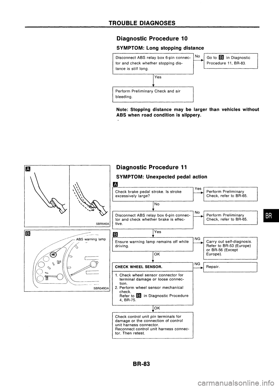
TROUBLEDIAGNOSES
Diagnostic Procedure10
SYMPTOM: Longstopping distance
Disconnect ABSrelay box6-pin connec- No
tor and check whether stopping dis-
tance isstill long.
Perform Preliminary Checkandair
bleeding. Go
to
IiJ
inDiagnostic
Procedure 11.SR-83.
Note: Stopping distancemaybelarger thanvehicles without
ABS when roadcondition isslippery.
Diagnostic Procedure11
SYMPTOM: Unexpected pedalaction
m
Check brakepedalstroke. Isstroke
excessively
large?
No
Disconnect ASSrelay box6-pin connec-
tor and check whether brakeiseffec-
SBR540A tive.
Yes
Ensure warning lampremains offwhile
driving.
OK
CHECK WHEEL SENSOR.
1. Check wheelsensor connector for
terminal damageorloose connec-
tion.
2. Perform wheelsensor mechanical
check. Refer to
IiJ
inDiagnostic Procedure
4, BR-75.
OK
Check control unitpinterminals for
damage orthe connection ofcontrol
unit harness connector.
Reconnect controlunitharness connec-
tor. Then retest.
BR-83
Yes
Perform Preliminary
Check. refertoSR-65.
Perform Preliminary
Check. refertoSR-65.
Carry outself-diagnosis.
Refer toBR-53 (Europe)
or SR-56 (Except
Europe).
Repair.
•
Page 354 of 1701
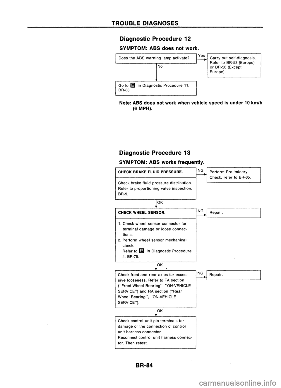
TROUBLEDIAGNOSES
Diagnostic Procedure12
SYMPTOM: ASSdoes notwork.
Does theABS warning lampactivate?
No
Go to
Ii)
inDiagnostic Procedure11,
BR-83.
Yes
Carryoutself-diagnosis.
Refer toBR-53 (Europe)
or BR-55 (Except
Europe).
Note: ABSdoes notwork when vehicle speedisunder 10km/h
(6 MPH).
Diagnostic Procedure13
SYMPTOM: ASSworks frequently.
CHECK BRAKEFLUIDPRESSURE.
Check brakefluidpressure distribution.
Refer toproportioning valveinspection,
BR-9.
OK
CHECK WHEEL SENSOR.
1. Check wheelsensor connector for
terminal damage orloose connec-
tions.
2. Perform wheelsensor mechanical
check.
Refer to
Ii)
inDiagnostic Procedure
4, BR-75.
OK
Check frontandrear axles forexces-
sive looseness. RefertoFA section
("Front WheelBearing", "ON-VEHICLE
SERVICE") andRAsection ("Rear
Wheel Bearing", "ON-VEHICLE
SERVICE").
OK
Check control unitpinterminals for
damage orthe connection ofcontrol
unit harness connector.
Reconnect controlunitharness connec-
tor. Then retest.
BR-84 NG
NG
NG
Perform
Preliminary
Check, refertoBR-55.
Repair.
Repair.