Page 430 of 1701
Type1
Type 2
Brush wear
limit line
SEL034Z
Type 1 CHARGING
SYSTEM
Brush Check
1. Check smooth movement ofbrush.
• Not smooth ...Check brushholder andclean.
2. Check brushforwear.
• Replace brushifit is worn down tothe limit line.
Stator Check
1. Continuity test
• Nocontinuity ...Replace stator.
2. Ground test
• Continuity exists...Replace stator.
Type 2
II
I
------_~
SEL037Z
EL-58
Page 431 of 1701
CHARGINGSYSTEM
Diode Check
MAIN DIODES
• Use anohmmeter tocheck condition ofdiodes asindicated inchart below.
• Ifany ofthe test results isnot satisfactory, replacediodeassembly.
Ohmmeter probes
Judgement
Positive
EB
Negative
e
Positive diodeplate Diodeterminals
Diodeconducts inonly one
Diodes check(Positive side)
direction.
Diode terminals Positivediodeplate
Negative diodeplate Diodeterminals
Diodeconducts inonly one
Diodes check(Negative side)
direction.
Diode terminals Negative
diodeplate
Type 1 Type
4
SEL039Z•
Sub-diodes
Positive
diode plate
Type
6 \Negative diodeplate
\ Diode
terminals
Type
5
Negative diodeplate
Negative diode
plate
(Stator side)
Type
3
Type
2
EL-59
Page 432 of 1701
Amountofprotrusion:
Fix ring atthe position
OfR~~wnlmum protrusion.
,,,,'
.
~~
,
~...
\
-
,'.:'
;
.',
,
"
Eccentric '
<-'
>/
groovy
Rearbearing
SEL044Z
SEL048Z
SEl049Z CHARGING
SYSTEM
Assembly RING FITTING INREAR BEARING
• Fix ring intogroove inrear bearing sothat itis as close to
the adjacent areaaspossible.
CAUTION:
Do not reuse rearbearing afterremoval.
REAR COVER INSTALLATION
(1) Fitbrush assembly, diodeassembly, regulatorassembly
and stator.
(2) Push brushes upwith fingers andinstall themtorotor.
Take carenottodamage slipring sliding surface.
EL-60
Page 433 of 1701
CHARGINGSYSTEM
Service DataandSpecifications (SOS)
ALTERNATOR
A5T06891LR170-746E LR170-504B A2T82491A
Type MITSUBISHIHITACHIMITSUBISHI
Applied model GA
engines CD20SR20DE
Nominal rating V-A
12-70 12-80
Ground polarity Negative
Minimum revolutions
under no-load Less
than
Lessthan1,000 Less
than
(when 13.5Visapplied) 1,300 1,300
rpm
Hot output current More
than Morethan
(When 13.5Visapplied) More
than 22/1,300 27/1,300
Morethan
.
21/1,300
Morethan More
than 22/1,300
More than 50/2,500 56/2,500More
than
50/2,500 Morethan Morethan 65/2,500
A/rpm 67/5,000
66/5,000
Regulated output
14.1-14.7
voltage V
Minimum lengthof
50(0.197) 6.0
(0.236) 5.0(0.197)
brush mm(in)
Brush spring pressure 4.609
-5.786 1.0-343 0.92
-328 4.609-5.786
(470 -590, (102
-350, (94-334, (470
-590,
N (g, oz)
16.58 -20.81) 3.60
-12.34) 332-11.78) 16.58
-20.81)
Slip ringminimum
221(0.870) 26.0
(1.024) 31.6(1.244) 221(0.870)
diameter mm(in)
Rotor coilresistance at
2.5-2.9 258 4824
-29
20'C (68'F)
n
EL-61
•
Page 864 of 1701
TROUBLEDIAGNOSIS FORNON-DETECTABLE ITEMS
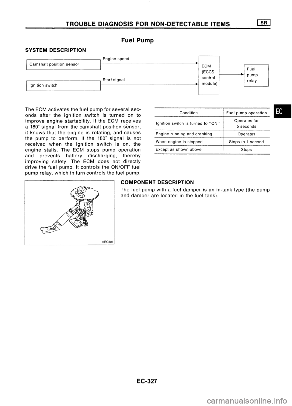
Fuel Pump
SYSTEM DESCRIPTION
Enginespeed
Camshaft positionsensor
Startsignal
Ignition switch
The ECM activates thefuel pump forseveral sec-
onds aftertheignition switchisturned onto
improve enginestartability. Ifthe ECM receives
a 180
0
signal fromthecamshaft positionsensor,
it knows thattheengine isrotating, andcauses
the pump toperform. Ifthe 180
0
signal isnot
received whentheignition switchison, the
engine stalls.TheECM stops pump operation
and prevents batterydischarging, thereby
improving safety.TheECM does notdirectly
drive thefuel pump. Itcontrols theON/OFF fuel
pump relay, which inturn controls thefuel pump.
ECM
(ECCS
control module)
Condition
Ignition switchisturned toON.
Engine running andcranking
When engine isstopped
Except asshown above Fuel
pump relay
Fuel pump operation
Operates for
5 seconds
Operates
Stops in1second
Stops
•
COMPONENT DESCRIPTION
A turbine typedesign fuelpump isused inthe fuel tank.
AEC801
EC-145
Page 1046 of 1701

TROUBLEDIAGNOSIS FORNON-DETECTABLE ITEMS
Fuel Pump
SYSTEM DESCRIPTION
I
Camshaft positionsensor
I
Engine speed
~
ECM
(ECCS Fuel
control pump
!,gnition switch Start
signal
relay
I
module)
The ECM activates thefuel pump forseveral sec-
onds aftertheignition switchisturned onto
improve enginestartability. Ifthe ECM receives
a 180
0
signal fromthecamshaft positionsensor,
it knows thattheengine isrotating, andcauses
the pump toperform. Ifthe 180
0
signal isnot
received whentheignition switchison, the
engine stalls.TheECM stops pump operation
and prevents batterydischarging, thereby
improving safety.TheECM does notdirectly
drive thefuel pump. Itcontrols theON/OFF fuel
pump relay,which inturn controls thefuel pump.
Condition
Ignition switchisturned to"ON"
Engine running andcranking
When engine isstopped
Except asshown above Fuel
pump operation •
Operates for
5 seconds
Operates
Stops in1second
Stops
COMPONENT DESCRIPTION
The fuel pump withafuel damper isan in-tank type(thepump
and damper arelocated inthe fuel tank).
AECB01
EC-327
Page 1117 of 1701
SEC5658Enginecoolant temperature sensor
Check engine coolant temperature sensorresistance.
Key-in switch
Check continuity betweenterminals ofkey-in switch connector.
11.5
5.6
3.7
1.2
Resistance
kfl
Continuity
No continuity
Continuity shouldexist.
Ignition
key
Not inserted
Inserted
Coolant
temp.°C('F)
-15 (5)
0(32)
10 (50)
40 (104)
TROUBLE
DIAGNOSES
Quick-glow System(Cont'd)
3. Install glowplugconnecting platesecurely.
Connecting
plate
Spring washer
~GIOwnut
Glow harness
Alternator
Refer to"CHARGING SYSTEM"inEL section.
EC-398
Page 1371 of 1701

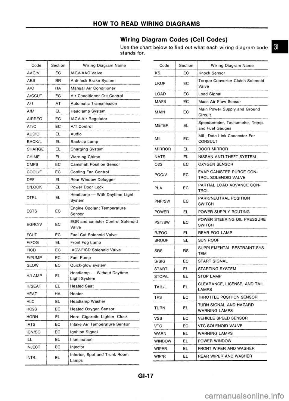
HOWTOREAD WIRING DIAGRAMS
Wiring Diagram Codes(CellCodes)
Use thechart below to'find outwhat each wiring diagram code•
stands for,
Code Section WiringDiagram Name
AACIV ECIACV-AAC
Valve
ABS BR
Anti-lock BrakeSystem
A/C HAManualAirConditioner
A/CCUT ECAir
Conditioner CutControl
A/T ATAutomatic Transmission
AIM ELHeadlamp System
AIRREG ECIACV-Air Regulator
AT/C ECA/TControl
AUDIO ELAudio
BACK/L ELBack-up Lamp
CHARGE ELCharging System
CHIME ELWarning Chime
CMPS EC
Camshaft PositionSensor
COOllF ECCooling
FanControl
DEF ELRearWindow Defogger
D/LOCK ELPowerDoorLock
DTRL ELHeadlamp
-With Daytime Light
System
ECTS ECEngine
Coolant Temperature
Sensor
EGR andcanister ControlSolenoid
EGRCIV EC
Valve
FCUT ECFuel
CutSolenoid Valve
F/FOG ELFront
FogLamp
FICO ECIACV-FICD
SolenoidValve
F/PUMP ECFuel
Pump
GLOW ECQuick-glow
system
H/LAMP ELHeadlamp
-Without Daytime
Light System
H/SEAT ELHeated
Seat
HEAT HA
Heater
HLC ELHeadlamp
Washer
H02S ECHeated
Oxygen Sensor
HORN ELHorn,
Cigarette Lighter,Clock
IATS ECIntake
AirTemperature Sensor
IGN/SG ECIgnition
Signal
ILL ELIllumination
INJECT ECInjector
INT/L ELInterior,
SpotandTrunk Room
Lamps Code
Section WiringDiagram Name
KS ECKnock
Sensor
LKUP ECTorque
Converter ClutchSolenoid
Valve
LOAD ECLoadSignal
MAFS ECMass
AirFlow Sensor
MAIN ECMain
Power Supply andGround
Circuit
METER ELSpeedometer,
Tachometer,Temp.
and Fuel Gauges
MIL ECMIL,
Data LinkConnector For
CONSULT
MIRROR ELDOOR
MIRROR
NATS ELNISSAN
ANTI-THEFT SYSTEM
02S ECOXYGEN
SENSOR
EC EVAP
CANISTER PURGECON-
PGCIV TROLSOLENOID VALVE
PLA ECPARTIAL
LOADADVANCE CON-
TROL
EC PARK/NEUTRAL
POSITION
PNP/SW SWITCH
POWER ELPOWER
SUPPLY ROUTING
POWER STEERING OILPRESSURE
PST/SW EC
SWITCH
R/FOG ELREAR
FOGLAMP
SROOF ELSUN
ROOF
SUPPLEMENTAL RESTRAINTSYS-
SRS RS
TEM
S/SIG ECST
ART SIGNAL
START ELSTARTING
SYSTEM
STOP/L ELSTOP
LAMP
TAllIL ELCLEARANCE,
LICENSE,ANDTAIL
LAMPS
TPS ECTHROTTLE
POSITIONSENSOR
TURN SIGNAL ANDHAZARD
TURN EL
WARNING LAMPS
VSS ECVEHICLE
SPEEDSENSOR
VTC ECVTC
SOLENOID VALVE
WARN ELWARNING
LAMPS
WINDOW ELPOWER
WINDOW
WIPER ELFRONT
WIPERANDWASHER
WIP/R ELREAR
WIPER ANDWASHER
GI-17