Page 403 of 1701

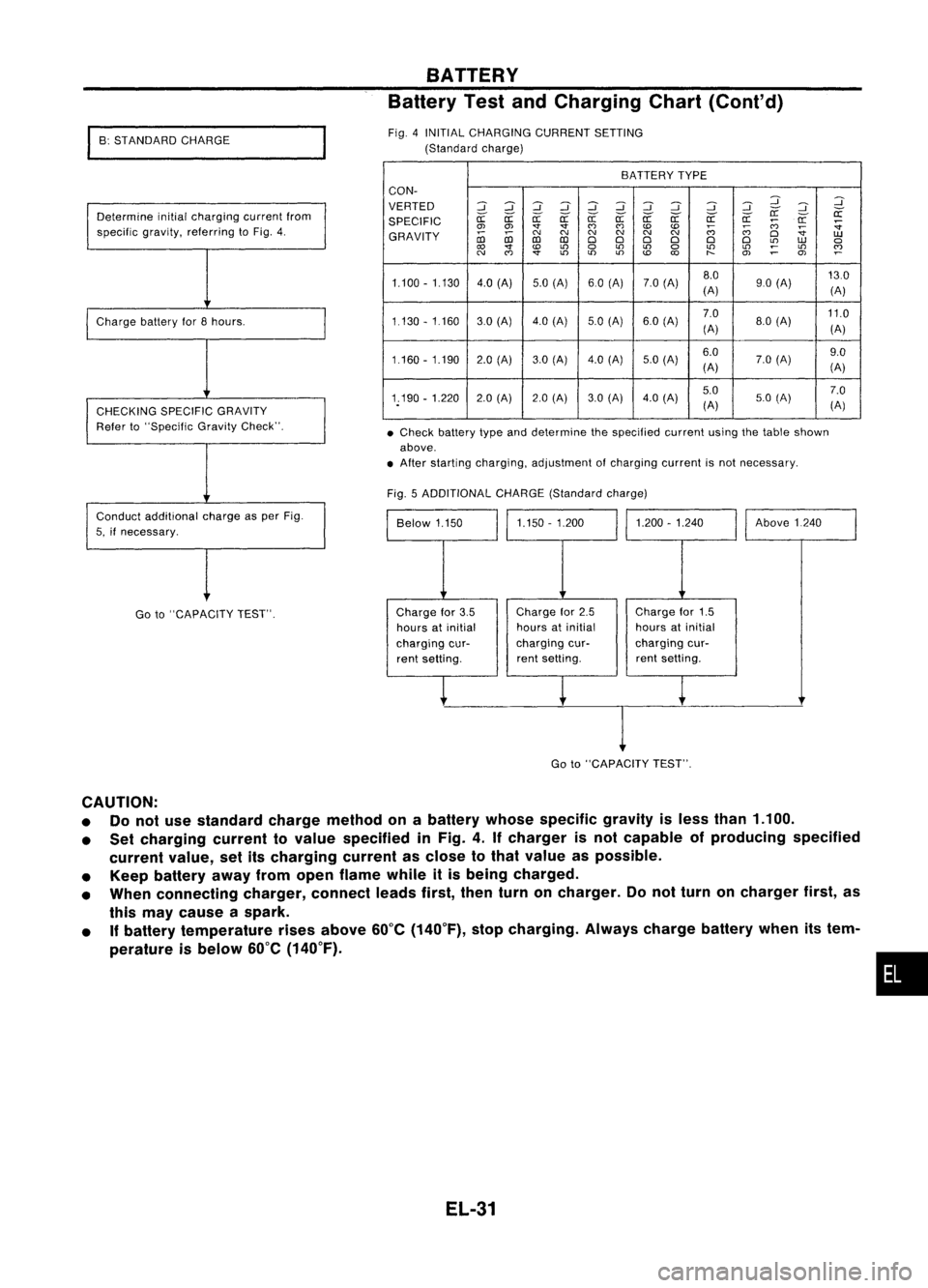
•Check battery typeanddetermine thespecified currentusingthetable shown
above .
• After starting charging, adjustment ofcharging currentisnot necessary.
BATTERY
Battery TestandCharging Chart(Cont'd)
BATTERY TYPE
CON-
VERTED
::J::J
~::J
::J
::J::J ::J ::J
::J
:J
:J
~
SPECIFIC
er:-
er:-
a:
er:-er:- er:-er:- er:- er:- er:-er:-
a:
;:;:;
a:
:;
0> 0> '1"'1"
(')
(')
to to
;:;:;
~
:;
GRAVITY
coco
C'J
C'J C'J
C'JC'J
C'J
(')
D
UJ
co co
DDD D D
D
L!)
UJ
a
'1"
to
L!)
a
L!)
L!)
a
L!)
L!)
~
L!)
~
C'J
(')
'1"
L!)
L!)L!)
to
t-
O>
~
OJ
1.100 -1.130 4.0(A) 5.0(A) 60(A) 7.0(A) 8.0
130
(A) 90
(A)
(A)
1.130 -1160 30(Al 4.0(Al 5.0
(A) 6.0(A) 7.0
11.0
(A) 8.0
(A)
(A)
1.160 -1.190 2.0(A) 3.0(Al 4.0
(A)
5.0(Al 6.0
7.0(A) 9.0
(A) (A)
1.190 -1.220 2.0(A) 2.0(A) 3.0(A) 4.0
(A) 5.0
7.0
(A) 5.0
(A)
(A)
Fig. 5ADDITIONAL CHARGE(Standard charge)
Above1240
1.200 -1.240
1.150 -1.200
Below 1.150
Fig.
4INITIAL CHARGING CURRENTSETTING
(Standard charge)
Determine initialcharging currentfrom
specific gravity,referring toFig. 4.
Charge batteryfor8hours.
CHECKING SPECIFICGRAVITY
Refer to"Specific GravityCheck".
Conduct additional chargeasper Fig.
5, ifnecessary.
I
B: STANDARD CHARGE
Go to"CAPACITY TEST". Charge
for3.5
hours atinitial
charging cur-
rent setting. Charge
for2.5
hours atinitial
charging cur-
rent setting. Charge
for1.5
hours atinitial
charging cur-
rent setting.
I
Go to"CAPACITY TEST".
CAUTION:
• Donot use standard chargemethod onabattery whosespecific gravityisless than 1.100.
• Set charging currenttovalue specified inFig. 4.Ifcharger isnot capable ofproducing specified
current value,setitscharging currentasclose tothat value aspossible.
• Keep battery awayfromopen flame whileitis being charged.
• When connecting charger,connectleadsfirst,thenturnoncharger. Donot turn oncharger first,as
this may cause aspark.
• Ifbattery temperature risesabove 60°C(140°F), stopcharging. Alwayschargebatterywhenitstem-
perature isbelow 60°C(140°F).
•
EL-31
Page 404 of 1701

I
C: QUICK CHARGE
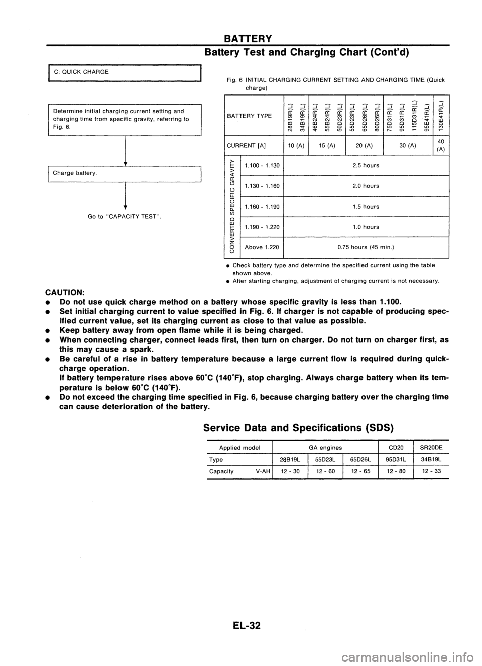
Determine initialcharging currentsettingand
charging timefrom specific gravity,referring to
Fig. 6.
I
Charge battery.
Goto"CAPACITY TEST".
BATTERY
Battery TestandCharging Chart(Cont'd)
Fig. 6INITIAL CHARGING CURRENTSETTINGANDCHARGING TIME(Quick
charge)
:::J:::J:::J:::J :::J:::J:::J
d dd
:::J
:::J :::J
~ ~
SA TTERY TYPE
~
~ ~~~~ ~a: a:a:
;;:;
~
~
0>
0>
""
""
C')
C')
CDCD
;;:;
;;:;
~
co co
C\I
N
C\I
N
C\I
N
Cl
W
D:l D:l
ClCl ClCl ClCl
L()
W
0
to
""
CD
L()
0
L()
L()
0
L()
L()
;:
L()
~
N
C')
""
L()
L()L()
CD
to
t-
O>
0>
CURRENT [A]10(A) 15(A) 20(A) 30(A) 40
(A)
>-
I-
1.100 -1.130 2.5
hours
:>
a:
(!J 1.130 -1.160 2.0
hours
0
u::
U
w
1.160 -1.190 1.5hours
0-
w
Cl
w
1.190 -1.220 1.0hours
I-
a:
w
>
z
0
Above 1.220 0.75
hours (45min.)
0
• Check battery typeanddetermine thespecified currentusingthetable
shown above.
• After starting charging, adjustment ofcharging currentisnot necessary.
CAUTION: • Donot use quick charge method onabattery whosespecific gravityisless than 1.100.
• Set initial charging currenttovalue specified inFig. 6.Ifcharger isnot capable ofproducing spec-
ified current value,setitscharging currentasclose tothat value aspossible.
• Keep battery awayfromopen flame whileitis being charged.
• When connecting charger,connectleadsfirst,thenturnoncharger. Donot turn oncharger first,as
this may cause aspark.
• Becareful ofarise inbattery temperature becausealarge current flowisrequired duringquick-
charge operation.
If
battery temperature risesabove 60°C(140°F), stopcharging. Alwayschargebatterywhenitstem-
perature isbelow 60°C(140°F).
• Donot exceed thecharging timespecified inFig. 6,because charging batteryoverthecharging time
can cause deterioration ofthe battery.
Service DataandSpecifications (SOS)
Applied model GA
engines CD20SR20DE
Type 26S19L
55D23L65D26L 95D31L
34S19L
Capacity V-AH
12-30 12
-60 12-65 12-80 12
-33
EL-32
Page 407 of 1701

STARTINGSYSTEM
Trouble Diagnoses
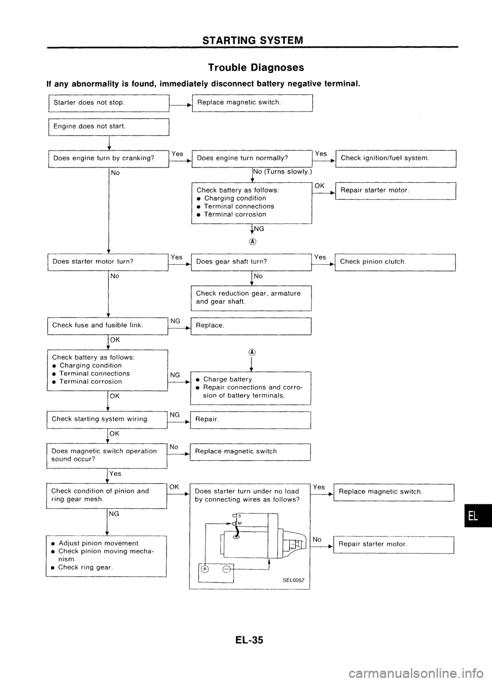
If any abnormality isfound, immediately disconnectbatterynegative terminal.
Starter doesnotstop.
Engine doesnotstart. Replace
magnetic switch.
Does engine turnbycranking? Doesengine turnnormally? Check
ignition/fuel system.
No No
(Turns slowly.)
Check battery asfollows:
OK
Repairstarter motor.
• Charging condition
• Terminal connections
• Terminal corrosion
NG
@
Does starter motorturn? Yes
Doesgearshaft turn? Checkpinionclutch.
No No
Check reduction gear,armature
and gear shaft.
Check fuseandfusible link. Replace.
OK
Check battery asfollows:
@
• Charging condition
• Terminal connections
NG
• Terminal corrosion •
Charge battery.
• Repair connections andcorro-
OK
sian
ofbattery terminals.
Check starting systemwiring.
Repair.
OK
Does magnetic switchoperation No
Replace magnetic switch
sound occur?
Yes
Check condition ofpinion and
OK
Doesstarter turnunder noload Yes
Replace magnetic switch.
ring gear mesh.
byconnecting wiresasfollows?
NG
•
• Adjust pinionmovement.
Repairstarter motor.
• Check pinionmoving mecha-
nism .
• Check ringgear.
SELOO9Z
EL-35
Page 424 of 1701
CHARGINGSYSTEM
Wiring Diagram -CHARGE -
GASOLINE ENGINEMODELS
EL-CHARGE-01
Referto
EL-POWER.
LHD models
RHO models
AIT
models
MIT
models
For Europe
Except@
FUSE
BLOCK
(JIB)
~
(0:
@:
@:
@:
@:
@:
@: GAengine
@: SRengine
@:
Withtachometer
@:
Without tachometer
~f1"'@
6,@B
*2 @30 ,@40
*3 @40 ,
@
3
.,
B
!
@QID
IGNITION
SWITCH
ON or START
Refer to
EL-POWER.
FUSIBLE
LINK AND
FUSE BOX
~
~
7.5A
mJ
RIB
lOA
[]]
1~11
Y
COMBINATION
I~
METER
(CHARGE
WARNING
LAMP)
(M30)
~ 1*.31
Y/R
~2 ~Y/R
-ee-~
JOINT ~
()~ CONNECTOR-l~~
~ ()-ID-I
~ Y/R Y/R
RIB R/B@@
Irku@
In-'
~ ~ ,..,JI,.,~
(E26)
'"T-'~
4JOINT
~ @D
IJ¥!I
(E201) (E203) Y
IR
EU
~gNNECTOR
RIB
R/B@@
I @l
<;>
{(100
I
y
~I
Y/R
~~
~@jg)
Y/R
m
RIB
n1-lI
AL TERNATOR ~~~
~-------------------------------,
L
j
~~ ~~~@D
~BR ~B~ B~~,~
rn::rm
BGY Refer
tolast page
(Foldout page).
@,
~
m~
,
r-----------------,
:~~~~~~:
11m ~
GY
ISI
I
I I
L
j
~~
~OR
HEL196
EL-52
Page 425 of 1701
CHARGINGSYSTEM
Wiring Diagram -CHARGE -(Cont'd)
DIESEL ENGINE MODELS
EL-CHARGE-02
•
LHO
models
RHO models
(1):
@:
Refer
to
EL-POWER.
FUSE
BLOCK
(JIB)
Refertolast page
(Foldout page).
aID
I
.,
B
!
~
10A
[]]
I
N~ll
Y
IJ
COMBlNA TION
METER
(CHARGE WARNING
~ LAMP)
I ~
JOINT
Y/R CONNECTOR-1~
f-
Y/R~--~ Y/R
1
Y/R Y/R
,c:r
l
eMB) ~eMB)
IQl::!J
I~I
Y/R Y/R
1~lm IclJl~
'T"
eE202)
'T"~
Y/R Y/R
t~;..- __
I
I
Y/R
1m,
~~
~GY
Refer
to
EL-POWER.
RIB
U+JI
AL TERNATOR ~~~
~@QJ)
~ GY
---:l,7.5A
ljJOO
RIB
I
O~
~ I
RIB RIB
,c!J, ~
,ell,~
'T"~ 'T"~
RIB RIB
<;>
I
J~
r-----------------,
: ~ ~ ,R..~ ~~: ~ ~
CillIillIillTII ~
I ~
\b:.@
GY
lSJ
I
mz:l]:l
B~ BR
I I
L ~
HEL197
EL-53
Page 426 of 1701

CHARGINGSYSTEM
Trouble Diagnoses
Before conducting analternator test,make surethatthebattery isfully charged. A3D-volt voltmeter and
suitable testprobes arenecessary forthe test. Thealternator canbechecked easilybyreferring tothe
Inspection Table.
Before starting, inspectthefusible link.
WITH IeREGULATOR
Burned-out
bulb.
Replace and
proceed to
"@".
Light "ON"
Light "OFF"
Connect
connector (S,
L) and
ground F
terminal
Engine
speed: 1,500 rpm
(Measure B
terminal
voltage)
Make sure
connector (S,L)is
connected
correctly.
(HITACHI
make)
'See
4)for grounding Fterminal.
(MITSUBISHI
make)
Check or
replace drive
belt.
Light "ON"
Light "OFF"
Disconnect
connector (S,
L) and
ground L
lead wire.
Engine
speed:
1,500 rpm
Lighting
switch "ON"
With
alternator sideLterminal
grounded. internalshortoccurs
when
+
diode isshort-circuited.
Light "ON
Dim
light
Light flickers
Bright light
Light
"ON"
Light
"OFF"
Ignition
switch "ON"
@
1) Use fully charged battery.
2) light: Charge warning light
ACG :Alternator partsexcept I'Cregulator
IC-RG :IC regulator
OK :IC-alternator isingood condition.
3) When reaching "Damaged ACG",remove
alternator fromvehicle anddisassembly, inspect
and correct orreplace faultyparts.
4) *Method ofgrounding Fterminal (HITACHI make
only)
Gasoline enginemodel
Contact tipofwire withbrush andattach
wire toalternator body.
~~~
;;z..'~~.~
~~~/j
S$.~~'
s<(r~, -
Brush liftwire
;;.. ~ Q<:::z"d,l'T7.
~ .. ~ ~-)o,IJ!"-f/
- -~~ C);
0~~/
'~-/i ~-,~
-~j~n
- <::::; -~ \•
'" 1A/-'
SEL030Z
5) Terminals
"S","l","B"
and
"E"
aremarked onrear cover ofalternator.
EL-54
Page 428 of 1701
CHARGINGSYSTE
Constr
t"
M
uc Ion (Cont'd)
~.N.m(k
g-m,
in-Ib)
~,N.m (kg-m, ft-Ib)
1jJ:
N.m(k
~. N g-m,in-Ib)
~_.. ..m (kg-m, ft-Ib)
~
7.8.10.8
(0.80 •1.10 69
• .4-95.5)
~
@
@~
@,
o
~
3.14.39 (0
.
.320 •0.398 •27.8 •34.5)
~ 3.14.3.9
(0.320 -0.398
L
O .~8-34~
lode assembly
IC regul atorassembly
•
l
Condenser
Stator
Brush
Slip
ring
RO'O'1
~ \~
A83.108
(8.5 •11 61
,
.80)
~3.14
-3.9 (03.20 -0.398
•27.8 -34.5)
Retainer \
Front bearing
Front cover
~~
~~ ~#Y
SEC. 231
A2T82491A
[ij3.9-5.4
(0.40 -0.55 34
, .7.47.7~
SEC.
231
LR170-746E
Pulley assembly
Front cover
Front bearing
Bearing retainer
@
Rotor
@
R
ear
bearing
(J)
Stator
MEL782DB
@
Ie
voltage regI
@
Diode assemb~ atorassembly
@)
Rear cover
EL-56
Page 429 of 1701
~:N.m (kg-m, ft-Ib)
SEL910T
SEL032Z
SEL033Z CHARGING
SYSTEM
Removal andInstallation
Disassembly
REAR COVER REMOVAL
C~UTION:
Rear cover maybehard toremove because aring isused to
lock outer raceofrear bearing. Tofacilitate removalofrear
cover, heatjustbearing boxsection witha200W soldering iron.
Do not use aheat gun, asitcan damage diodeassembly.
REAR BEARING
CAUTION:
• Do not reuse rearbearing afterremoval. Replacewitha
new one.
• Donot lubricate rearbearing outerrace.
Rotor Check
1. Resistance test
Resistance: RefertoSOS (EL-61).
• Not within thespecified values...Replace rotor.
2. Insulator test
• Continuity exists...Replace rotor.
3. Check slipring forwear.
Slip ring minimum outerdiameter:
Refer toSOS (EL-61).
• Not within thespecified values...Replace rotor.
EL-57
•