Page 154 of 1701
-Straightedge
Depth
gauge ASSEMBLY
Adjustment 2(Cont'd)
c. Measure dimension "P".
d. Calculate dimension "N".
• "N": Distance betweenoilpump fittingsurface oftransmis-
sion case andthrust washer onreverse clutchdrum.
N=O-P
Transmission case
pack
SAT383D
2.Measure dimensions "R"and "S"andthen calculate
dimension
"Q".
R
SAT384D
Straightedge
a.
Measure dimension "R".
b. Measure dimension "S".
c. Calculate dimension
"Q".
• "0": Distance betweentransmission casefitting surface
and thrust washer matingsurface.
O=R-S
3. Adjust reverse clutchendplay "T
4".
T
4
=
N-0
Reverse clutchendplay:
0.65 -1.00
mm
(0.0256 -0.0394
in)
• Select proper thickness ofthrust washer sothat reverse
clutch endplay iswithin specifications.
Thrust washer:
Refer toSDS, AT-173.
AT-154
Page 155 of 1701
Bearingrace
Thrustwasher SAT158E ASSEMBLY
Assembly 3
1. Remove reverseclutchassembly andinstall needle bearing
on high clutch assembly.
• Pay attention todirection ofneedle bearing.
2. Install reverse clutchassembly.
3. Install anchor endpin,washer andlock nutontransmission
case.
4. Place brake bandonoutside ofreverse clutchdrum.Tighten
. anchor endpinjust enough sobrake bandisevenly fitted
on reverse clutchdrum.
5. Place bearing raceselected intotal endplay adjustment •
step onoil pump cover.
• Apply petroleum jellytobearing race.
6. Place thrust washer selected inreverse clutchendplay step
on reverse clutchdrum.
• Apply petroleum jellytothrust washer.
7. Install oilpump assembly ontransmission case.
AT-155
Page 157 of 1701
SAT397D
Straightedge SAT695D
SAT696D ASSEMBLY
11. Apply compressed airtooil holes oftransmission caseand
check operation ofbrake band.
Adjustment 3
FINAL DRIVE ENDPLAY
_. Except model34X81-
• Measure clearance betweendifferential sidebearing and
transmission case.
• Select proper thickness ofadjusting shimsothat end play
is within specifications.
1. Measure dimension 'T"between sidebearing fittingsur-•
face oftransmission caseandconverter housingfittingsur-
face oftransmission case.
"T/':
indication ofgauge
2. Measure thickness ofstraightedge "t".
T
= T
1 -
t
3. Place finaldrive assembly onconverter housing.
4. Measure dimension "U"between endofdifferential case
and transmission casefitting surface ofconverter housing.
AT-157
Page 158 of 1701
ASSEMBLY
Adjustment 3
(Co nt'd)
5. Measure dimension "V"between endofdifferential case
and adjusting shimmating surface ofdifferential sidebear-
ing.
6. Calculate finaldrive endplay.
Final drive endplay:
T-U+V
7. Select proper thickness ofdifferential sidebearing adjust-
ing shim sothat final drive endplay iswithin specifications.
Final drive endplay:
0-
0.15
mm
(0-0.0059
in)
SAT697D Differentialsidebearing adjusting shim:
Refer to80S, AT-170.
Assembly 4
1. Install differential sidebearing adjusting shimselected in
final drive endplay adjustment stepontransmission case.
2. Install finaldrive assembly ontransmission case.
3. Install oiltube onconverter housing.
SAT134E AT-158
Page 159 of 1701

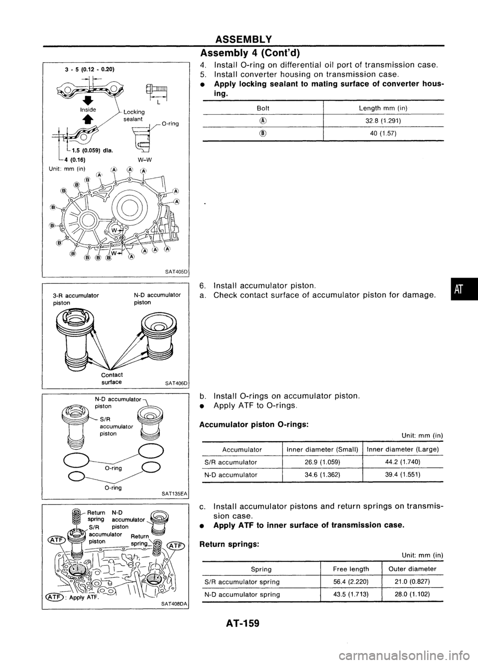
3-5 (0.12 •0.20)
6.Install accumulator piston.
a. Check contact surface ofaccumulator pistonfordamage.
ASSEMBLY
Assembly 4(Cont'd)
4. Install a-ring ondifferential oilport oftransmission case.
5. Install converter housingontransmission case.
• Apply locking sealant tomating surface ofconverter hous-
ing.
•
Length
mm(in)
32.8 (1.291)
40 (1.57)
@
@
Bolt
SAT405D
w-w
N-D accumulator
piston
Locking
sealant
~O'i"9
3-R accumulator
piston
Unit:
Contactsurface
SAT406D
N-D accumUlato'e
~iston ~
SIR ~
accumulator
piston
o
~C)
O~
O-ring
b.
Install a-rings onaccumulator piston.
• Apply ATFtoa-rings.
Accumulator pistonO-rings:
Unit:mm(in)
Accumulator Inner
diameter (Small) Inner
diameter (Large)
SIR
accumulator
26.9
(1.059) 44.2
(1.740)
N-D accumulator
34.6
(1.362) 39.4
(1.551)
SAT135EA
~ Return N-D ~
~ spring accumulator ~
~S/R piston
@)
accumulator Return
ATF .
t
pIS on spring~
tATi="
~~ ~~'\\~
~~U~~~-1C .....~.~ ..
}~y)~:
° ~~~'
o*lf
_~o_
00\\
II~o
~: ApplyATF.
r
c.
Install accumulator pistonsandreturn springs ontransmis-
sion case.
• Apply ATFtoinner surface oftransmission case.
Return springs:
Unit:mm(in)
Spring Free
length Outer
diameter
SIR
accumulator spring
56.4
(2.220) 21.0
(0.827)
N-D accumulator spring
43.5
(1.713) 28.0(1.102)
SAT408DA
AT-159
Page 161 of 1701
\~~~~~C0\
~~ \.---.!
~ />"0
o
<=~~ )'()
Throttle lever'~ ~\
~ Il';-,~\ ,~\\)
,./, Manual plate
2\ (
. ~ -P-' (\
d (
Detent valve
/- \, 'sdJ :----, \,,,
n\ ';\ ~ "~
Manualvalve
\3l~w1:
nd\'~~\ \\)~
\(--' "'!f ()~
r:,
A~
\ ~ SAT414D
SAT664D ASSEMBLY
Assembly 4(Conl'd)
b, Set manual shaftinNeutral position.
c. Install control valveassembly ontransmission casewhile
aligning manualvalvewithmanual plateanddetent valve
with throttle lever.
d. Pass solenoid harnessthroughtransmission caseand
install terminal bodyontransmission casebypushing
it.
e. Install cliptoterminal body.
f.
Tighten bolts@,
@. ~
and
@.
Bolt length, number andlocation:
Bolt
@
@ @
@
Bolt length
'T'
mm
(in)
33,0
40,0
43,525,0
(1.299) (1.575)(1,713)
(0.984)
Number ofbolts
652
2
Tightening torque
7-9 (0,7 -0.9, 61-78)
N'm (kg-m, in-Ib)
12. Install oilpan.
a. Attach magnet tooil pan.
AT-161
•
Page 162 of 1701
SAT070D
a-ring
SAT160EASSEMBLY
Assembly 4(Cont'd)
b. Install newoilpan gasket ontransmission case.
c. Install oilpan ontransmission case.
• Always replace oilpan bolts.
• Tighten thefour bolts inacriss-cross patterntoprevent
dislocation ofgasket.
d. Tighten drainplugtospecified torque.
13. Install governor valve.
a. Install governor valveassembly intotransmission case.
b. Install O-ring togovernor cap.
• Apply ATFtoa-ring.
c. Install governor caponto transmission case.
d. Install snapringonto transmission casewithascrewdriver.
• Align snapringgapwith thenotch oftransmission case.
AT-162
Page 163 of 1701
SAT620E
SAT586H
SAT428DA
Torque
converter
ASSEMBLY
Assembly 4(Cont'd)
14. Install inhibitor switch.
a. Set manual shaftin"P" position.
b. Temporarily installinhibitor switchonmanual shaft.
c.
Move
selector
lever
to"N" position.
d. Use a4mm (0.157 in)pin forthis adjustment.
1) Insert thepinstraight intothemanual shaftadjustment hole.
2) Rotate inhibitor switchuntilthepincan also beinserted
straight intohole ininhibitor switch.
e. Tighten inhibitor switchfixingbolts.
f. Remove pinfrom adjustment holeafter adjusting inhibitor
switch.
15. Install oilcharging pipeandoilcooler tubetotransmission •
case.
16. Install torque converter.
a. Pour ATFintotorque converter.
• Approximately 1liter (7/8Impqt)offluid isrequired fora
new torque converter.
• When reusing oldtorque converter, addthesame amount
of fluid aswas drained.
b. Install torque converter whilealigning notchesoftorque
converter withnotches ofoil pump.
AT-163