Page 1552 of 1701
SEC.320 MAJOR
OVERHAUL
Case Components
I
RS5F30A
&
RS5F31 A
I
.. -- RS5F31A---
~16 -21
(1.6 -2.1, 12. 15)
@ ~Mating
surface to
transmiSSion
case ----
@
~20 -29 (2.0 -3.0, 14-22)-
~ Thread ofbolt
(1)
Clutch housing
@)
O-ring
@
Input shaftoilseal
@
Case cover
@
Oilpocket
@
Back-up lampswitch
@
Bearing retainer
@
Differential oilseal
@
Bearing retainer
@
Drain plug
@
Torx screw
@l
Transmission case
(J)
Filler plug
@
Oilgutter
@
Airbreather
@
Reverse idlershaft
@
Welch plug
@
Oilchannel
MT-10
@
~
15-20 (1.5 -2.0, 11-14)
~ Thread ofbolt
Ij] :
Nom (kg-m, in-Ib)
tr'J :
Nom (kg-m, ft-Ib)
~ :Apply recommended sealant
(Nissan genuine part:KP610-00250) orequivalent.
*: :
Pay attention toits direction.
SMT755C
@
Striking rodoilseal
@J
Boot
@
Neutral position switch(GA
engine) orswitch plug(CD
engine)
@
Differential oilseal
@
O-ring
@
Speedometer pinionassembly
Page 1555 of 1701
DISASSEMBLV
I
RSSF30A
&
RSSF31 A
I
5th shift -
fork
Suitable
tool
SMT571
SMT082A SMT577
SMT579
1.
Remove transmission casewhile slightly tiltingitto prevent
5th shift forkfrom interfering withcase.
2. Draw outreverse idlerspacer andfork shaft, thenremove
5th and 3rd
&
4th shift forks.
• Becareful nottolose shifter cap.
3. Remove controlbracket with1st
&
2nd shift fork.
• Becareful nottolose shifter cap.
4. Remove gearcomponents fromclutch housing.
- RS5F30A-
a. Remove threescrews anddetach bearing retainer.
• One ofthese threescrews istorx type andshould be
removed withasuitable tool,asshown.
b. Remove inputshafttogether withmainshaft bytapping
lightly.
• Always withdraw mainshaft straightout.Failure todo so
can damage resinoilchannel onclutch housing side.
• Do not draw outreverse idlershaft fromclutch housing
because thesefittings willbeloose.
• When removing inputshaft, becareful nottoscratch oilseal
lip with shaft spline.
MT-13
•
Page 1568 of 1701
REPAIRFORCOMPONENT PARTS
Case Components (Cont'd)
2. Install inputshaft oilseal.
• Apply multi-purpose greaseto
installing.
SMT751BA
I
RSSF30A
&
RSSF31A
I
seal lipofoil seal before
Input shaftrearbearing
1. Remove welchplugfrom transmission case.
SMT688C
2.Remove inputshaft rearbearing bytapping itfrom welch
plug hole.
r
Welch plughole
SMT633
3.Install welchplug.
• Apply recommended sealanttomating surface oftransmis-
sion case.
4. Install inputshaft rearbearing.
MT-26
Page 1574 of 1701
ASSEMBLYI
RSSF30A
&
RSSF31 A
I
SMT720
c.
Install mainshaft assembly.
• Take carenottodamage oilchannel wheninserting main-
shaft intoclutch housing.
9. Apply grease toshifter caps,theninstall itto control
bracket. Installcontrol bracket with1st
&
2nd shift fork.
10. Install 3rd
&
4th and 5thshift forks.
11. Insert forkshaft.
• Apply multi-purpose greasetosupport springbefore install-
ing.
12. Install reverse idlerspacer.
13. Apply recommended sealanttomating surface ofclutch
housing.
14. Install transmission caseonclutch housing.
15. Measure totalturning torque.
Total (Final drive+Mainshaft) turningtorque(New
bearing): Refer toSOS, MT-62.
• When oldbearing isused again, turning torquewillbe
slightly lessthan theabove.
• Make suretorque isclose tothe specified range.
MT-32
Page 1575 of 1701

MAJOROVERHAUL
I
RS5F32A
I
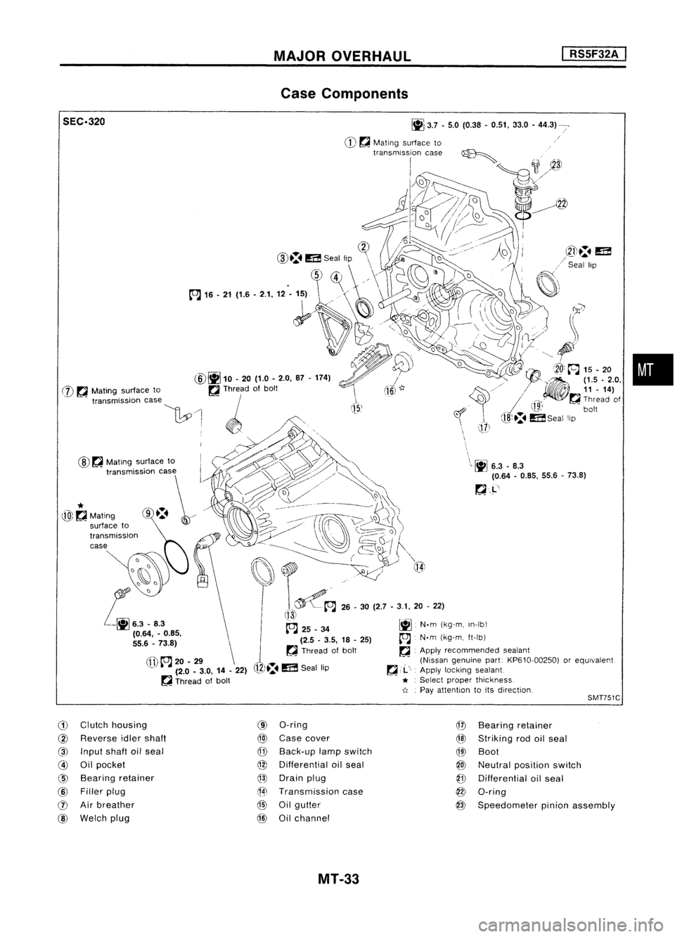
Case Components
•
\
\L~
6.3.8.3
(0.64 -0.85, 55.6-73.8)
~.L'
J
(15,'
~
3.7•5.0 (0.38 •0.51, 33.0-44.3)
CD ~
Mating surface to
transmission case~
I
;1
~3J
1J2»~
o//~
d~~~
!-~~
i~=1D.
(]?
CID.:.
m
Seal lip \
\
.
~)~
//\
1~
~'
(fl)
to.J
20-29 \
- (2.0-3.0, 14-22)
~ Thread ofbolt
@
~
Mating surface to
SEC.320
@~
10.20 (1.0-2.0, 87-174)
W ~
Mating surface to ~Thread ofbolt
"""mi"ioo '""
\1:.0
1 ~ /',
. WO,,~., .,.~
~~~> '\
t,,~~~~
o
I:::t:\ ~___-- __~
j)\~
~i)~/
(ro\~\~)
. ------ ~~,/ ~Q~
I
f""\
~~~ ..~ Q{
t~A
26-30 (2.7 -3.1, 20-22)
!13i
~ 25_34 ~N.m(kg-m, In-Ib\
(2.5 -3.5, 18-25)
A
N.m(kg-m, ft-Ib)
~ Thread ofbolt ~.Apply recommended sealant
(Nissan genuine part:KP610-00250) orequivalent
12)~.
m
Seal lip ~
,.1..',
Apply locking sealant
* :
Select proper thickness.
-tI .
Pay attention toits direction,
*
@~Mating
SMT751C
G)
Clutch housing
@
Reverse idlershaft
@
Input shaftoilseal
@
Oilpocket
@
Bearing retainer
@
Filler plug
(J)
Airbreather
@
Welch plug
(9)
O-ring
@
Case cover
CfD
Back-up lampswitch
@
Differential oilseal
@
Drain plug
@
Transmission case
@
Oilgutter
@
Oilchannel
@
Bearing retainer
@l
Striking rodoilseal
QID
Boot
@
Neutral position switch
@
Differential oilseal
@
O-ring
@
Speedometer pinionassembly
MT-33
Page 1593 of 1701
REPAIRFORCOMPONENT PARTS
I
RS5F32A
I
Shift Control Components (Cont'd)
3. Measure clearance "C"between reversebrakecamand
striking leverwhile shifting toreverse position.
Clearance
"C":
0.05 -0.125 mm(0.0020 -0.0049 in)
If "H" or"C" isnot within specification, replacethefollow-
ing parts asaset.
• Striking leverassembly
• Striking interlock assembly (Thisincludes reversebrake
earn.)
• Control bracketassembly
Reverse brakeeam
c SMT729B CaseComponents
REMOVAL ANDINSTALLATION
Input shaftoilseal
1. Drive outinput shaftoilseal.
2. Install inputshaftoilseal.
• Apply multi-purpose greasetoseal lipofoil seal before
installing.
SMT751BA
•
Input shaftrearbearing
1. Remove welchplugfrom transmission case.
SMT705B MT-51
Page 1617 of 1701

SRA696A
SRA697A
S
Control rod
Lateral link
~H";""I"
ITorsion
beam
SRA698AREAR
SUSPENSION
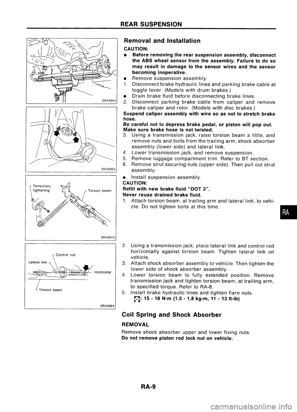
Removal andInstallation
CAUTION:
• Before removing therear suspension assembly,disconnect
the ABS wheel sensor fromtheassembly. Failuretodo so
may result indamage tothe sensor wiresandthesensor
becoming inoperative.
• Remove suspension assembly.
1. Disconnect brakehydraulic linesandparking brakecableat
toggle lever.(Models withdrum brakes.)
• Drain brake fluidbefore disconnecting brakelines.
2. Disconnect parkingbrakecablefromcaliper andremove
brake caliper androtor. (Models withdiscbrakes.)
Suspend caliperassembly withwire soasnot tostretch brake
hose.
Be careful nottodepress brakepedal, orpiston willpop out.
Make surebrake hoseisnot twisted.
3. Using atransmission jack,raise torsion beamalittle, and
remove nutsandbolts fromthetrailing arm,shock absorber
assembly (lowerside)andlateral link.
4. Lower transmission jack,andremove suspension.
5. Remove luggagecompartment trim.Refer toBT section.
6. Remove strutsecuring nuts(upper side).Thenpulloutstrut
assembly.
• Install suspension assembly.
CAUTION: Refill withnewbrake fluid"DOT
3".
Never reusedrained brakefluid.
1. Attach torsion beam,attrailing armandlateral link,tovehi-
cle. Donot tighten boltsatthis time.
2. Using atransmission jack,place lateral linkand control rod
horizontally againsttorsionbeam.Tighten laterallinkon
vehicle.
3. Attach shockabsorber assembly tovehicle. Thentighten the
lower sideofshock absorber assembly.
4. Lower torsion beamtofully extended position.Remove
transmission jackandtighten torsion beam,attrailing arm,
to specified torque.RefertoRA-8.
5. Install brakehydraulic linesandtighten flarenuts.
~: 15-18 N'm (1.5.1.8 kg-m,11-13 ft-Ib)
Coil Spring andShock Absorber
REMOVAL
Remove shockabsorber upperandlower fixing nuts.
Do not remove pistonrodlock nutonvehicle.
RA-9
•
Page 1672 of 1701

ON-VEHICLESERVICE
Checking andAdjusting DriveBelts(Forpower
steering)
Refer to"Checking DriveBelts" for"ENGINE MAINTENANCE"
in MA section.
SST476C
S
r
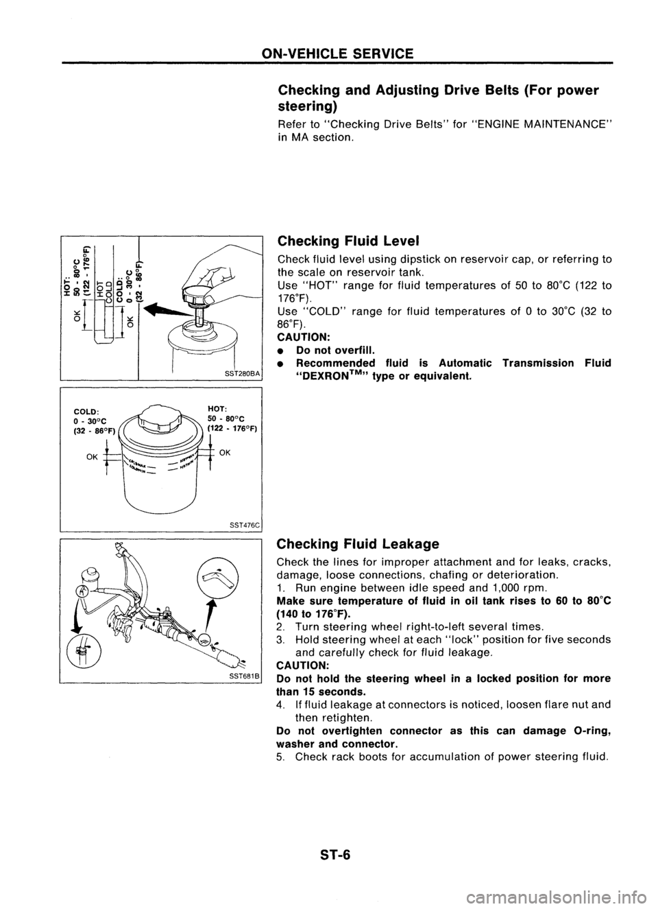
SST681B Checking
Fluidlevel
Check fluidlevel using dipstick onreservoir cap,orreferring to
the scale onreservoir tank.
Use "HOT" rangeforfluid temperatures of50 to80°C (122to
176°F).
Use "COLD" rangeforfluid temperatures of0to 30°C (32to
86°F).
CAUTION:
• Donot overfill.
• Recommended fluidisAutomatic Transmission Fluid
''DEXRON™,, typeorequivalent.
Checking Fluidleakage
Check thelines forimproper attachment andforleaks, cracks,
damage, looseconnections, chafingordeterioration.
1. Run engine between idlespeed and1,000 rpm.
Make suretemperature offluid inoil tank rises to60 to80°C
(140 to176°F).
2. Turn steering wheelright-to-Ieft severaltimes.
3. Hold steering wheelateach "lock" position forfive seconds
and carefully checkforfluid leakage.
CAUTION:
Do not hold thesteering wheelinalocked position formore
than 15seconds.
4. Iffluid leakage atconnectors isnoticed, loosenflarenutand
then retighten.
Do not overtighten connectorasthis candamage O-ring,
washer andconnector.
5. Check rackboots foraccumulation ofpower steering fluid.
ST-6