1995 NISSAN ALMERA N15 width
[x] Cancel search: widthPage 955 of 1701
A
N
600 1,000 1,4001,8002,200
Engine speed(rpm) SEF742M
Tp
(msec)
1.75
~ 1.50
.~
3l
1.25
:;
a.
c:
1.00
.Q
~ 0.75
E ENGINE
ANDEMISSION BASICCONTROL SYSTEMDESCRIPTION
Distributor Ignition(01)System (Cont'd)
SYSTEM DESCRIPTION
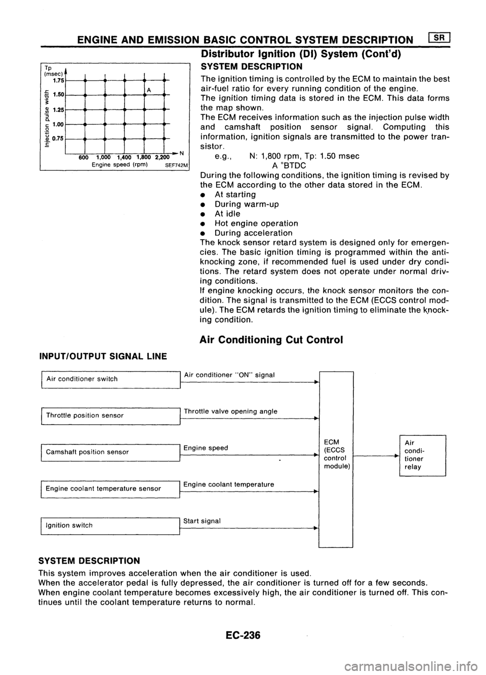
The ignition timingiscontrolled bythe ECM tomaintain thebest
air-fuel ratioforevery running condition ofthe engine.
The ignition timingdataisstored inthe ECM. Thisdataforms
the map shown.
The ECM receives information suchasthe injection pulsewidth
and camshaft positionsensorsignal.Computing this
information, ignitionsignalsaretransmitted tothe power tran-
sistor.
e.g., N:1,800 rpm,Tp:1.50 msec
AOBTDC
During thefollowing conditions, theignition timingisrevised by
the ECM according tothe other datastored inthe ECM.
• Atstarting
• During warm-up
• Atidle
• Hot engine operation
• During acceleration
The knock sensor retardsystem isdesigned onlyforemergen-
cies. Thebasic ignition timingisprogrammed withintheanti-
knocking zone,ifrecommended fuelisused under drycondi-
tions. Theretard system doesnotoperate undernormal driv-
ing conditions.
If engine knocking occurs,theknock sensor monitors thecon-
dition. Thesignal istransmitted tothe ECM (ECCS control mod-
ule). TheECM retards theignition timingtoeliminate thek.nock-
ing condition.
Air Conditioning CutControl
INPUT/OUTPUT SIGNALLINE
Air conditioner switch
Throttle position sensor
Camshaft positionsensor
Engine coolant temperature sensor
Ignition switch Air
conditioner "ON"signal
Throttle valveopening angle
Engine speed
Engine coolant temperature
Start signal
ECM
(ECCS
control module)
Air
condi-
tioner
relay
SYSTEM DESCRIPTION
This system improves acceleration whentheairconditioner isused.
When theaccelerator pedalisfully depressed, theairconditioner isturned offfor afew seconds.
When engine coolant temperature becomesexcessively high,theairconditioner isturned off.This con-
tinues untilthecoolant temperature returnstonormal.
EC-236
Page 977 of 1701
![NISSAN ALMERA N15 1995 Service Manual ON-BOARDDIAGNOSTIC SYSTEMDESCRIPTION
CONSULT (Conl'd)
Monitored item ECM
Main
[Unit] input
signals Description
Remarks
signals
AIR COND SIG •Indicates [ON/OFF] conditionofthe
[ON/OFF]
00
air
NISSAN ALMERA N15 1995 Service Manual ON-BOARDDIAGNOSTIC SYSTEMDESCRIPTION
CONSULT (Conl'd)
Monitored item ECM
Main
[Unit] input
signals Description
Remarks
signals
AIR COND SIG •Indicates [ON/OFF] conditionofthe
[ON/OFF]
00
air](/manual-img/5/57349/w960_57349-976.png)
ON-BOARDDIAGNOSTIC SYSTEMDESCRIPTION
CONSULT (Conl'd)
Monitored item ECM
Main
[Unit] input
signals Description
Remarks
signals
AIR COND SIG •Indicates [ON/OFF] conditionofthe
[ON/OFF]
00
air
conditioner switchasdetermined
by the airconditioning signal.
PIN POSI SW
00
•
Indicates [ON/OFF] conditionfromthe
[ON/OFF] park/neutralpositionswitchsignal.
PW/ST SIGNAL •Indicates [ON/OFF] conditionofthe
[ON/OFF]
00
power
steering oilpressure switch
determined bythe power steering oil
pressure signal.
INJ PULSE [msec]
0
•
Indicates theactual fuelinjection •
When theengine isstopped, acertain
pulse widthcompensated byECM computedvalueisindicated.
according tothe input signals.
IGN TIMING [BTDC]
0
•
Indicates theignition timingcomputed
by ECM according tothe input sig-
nals.
IACV-AACIV
[%]
•Indicates theidle aircontrol valve
0
(AAC
valve) control valuecomputed
by ECM according tothe input sig-
nals.
A/F ALPHA [%J •Indicates themean valueofthe air- •When theengine isstopped, acertain
0
fuel
ratio feedback correction factor valueisindicated.
per cycle. •This dataalsoincludes thedata for
the air-fuel ratiolearning control.
AIR COND RLY •Indicates theairconditioner relay
[ON/OFF]
0
control
condition (determined byECM
according tothe input signal).
FUEL PUMP RLY •Indicates thefuel pump relaycontrol
[ON/OFFJ
0
condition
determined byECM accord-
ing tothe input signals.
COOLING FAN
•Indicates thecontrol condition ofthe
[HI/LOW/OFFJ coolingfans(determined byECM
0
according
tothe input signal).
HI ...High speed operation
LOW ...Low speed operation
OFF ...Stopped
EGRC SOLIV •Indicates thecontrol condition ofthe
[ON/OFFJ EGR
valve
&
EVAP canister Purge
control solenoid valve(determined by
0
ECM
according tothe input signal).
ON ...EGR andEVAP canister purge
operation cut-off
OFF ...EGR andEVAP canister purge
operation notcut-off
VOLTAGE •Voltage measured bythe voltage
[V] probe.
PULSE •Pulse width, frequency orduty cycle •Only "#"isdisplayed ifitem is
[msec] or[Hz] or
measuredbythe pulse probe. unabletobe measured.
[%]
•Figures with"#"s aretemporary
ones. Theyarethesame figures as
an actual pieceofdata which wasjust
previously measured.
EC-258
Page 1218 of 1701
T(Margin thickness)
--1,-
ml
a
III' ~
o
~-
-L
d
SEM8928
I
.\
SEM188A
CYLINDER
HEAD
Inspection (Conl'd)
3. Heat cylinder headto110 to120°C (230to248°F).
4. Press fitvalve seatuntilitseats onthe bottom .
5. Cut orgrind valve seatusing suitable toolatthe specified
dimensions asshown inSOS (EM-159).
6. After cutting, lapvalve seatwithabrasive compound.
7. Check valveseating condition.
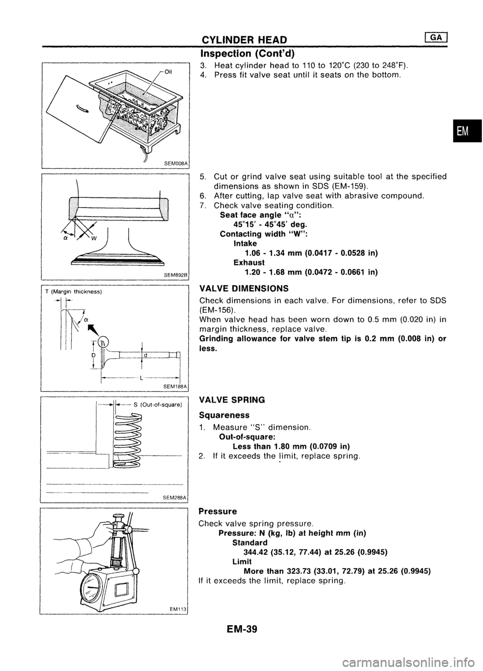
Seat faceangle "a":
45°15' -45°45' deg.
Contacting width"W":
Intake
1.06 -1.34 mm(0.0417 -0.0528 in)
Exhaust
1.20 -1.68 mm(0.0472 -0.0661 in)
VALVE DIMENSIONS
Check dimensions ineach valve. Fordimensions, refertoSOS
(EM-156).
When valveheadhasbeen worn down to0.5 mm (0.020 in)in
margin thickness, replacevalve.
Grinding allowance forvalve stemtipis0.2 mm (0.008 in)or
less.
•
SEM288A VALVE
SPRING
Squareness
1. Measure "S"dimension.
Out-of-square: Less than1.80mm(0.0709 in)
2. Ifitexceeds thelimit, replace spring.
EM113
Pressure
Check valvespring pressure.
Pressure: N(kg, Ib)atheight mm(in)
Standard 344.42 (35.12, 77.44)at25.26 (0.9945)
Limit More than323.73 (33.01, 72.79)at25.26 (0.9945)
If itexceeds thelimit, replace spring.
EM-39
Page 1271 of 1701
T(Margin thickness)
~I
r
nw
a
III' ~
D
L
-l
d
SEM892B
SEM188A CYLINDER
HEAD
Inspection (Cont'd)
3. Heat cylinder headto110 to130°C (230to266°F).
4. Press fitvalve seatuntil itseats onthe bottom.
5. Cut orgrind valve seatusing asuitable toolatthe specified
dimensions asshown inSDS (EM-165).
6. After cutting, lapvalve seatwithabrasive compound.
7. Check valveseating condition.
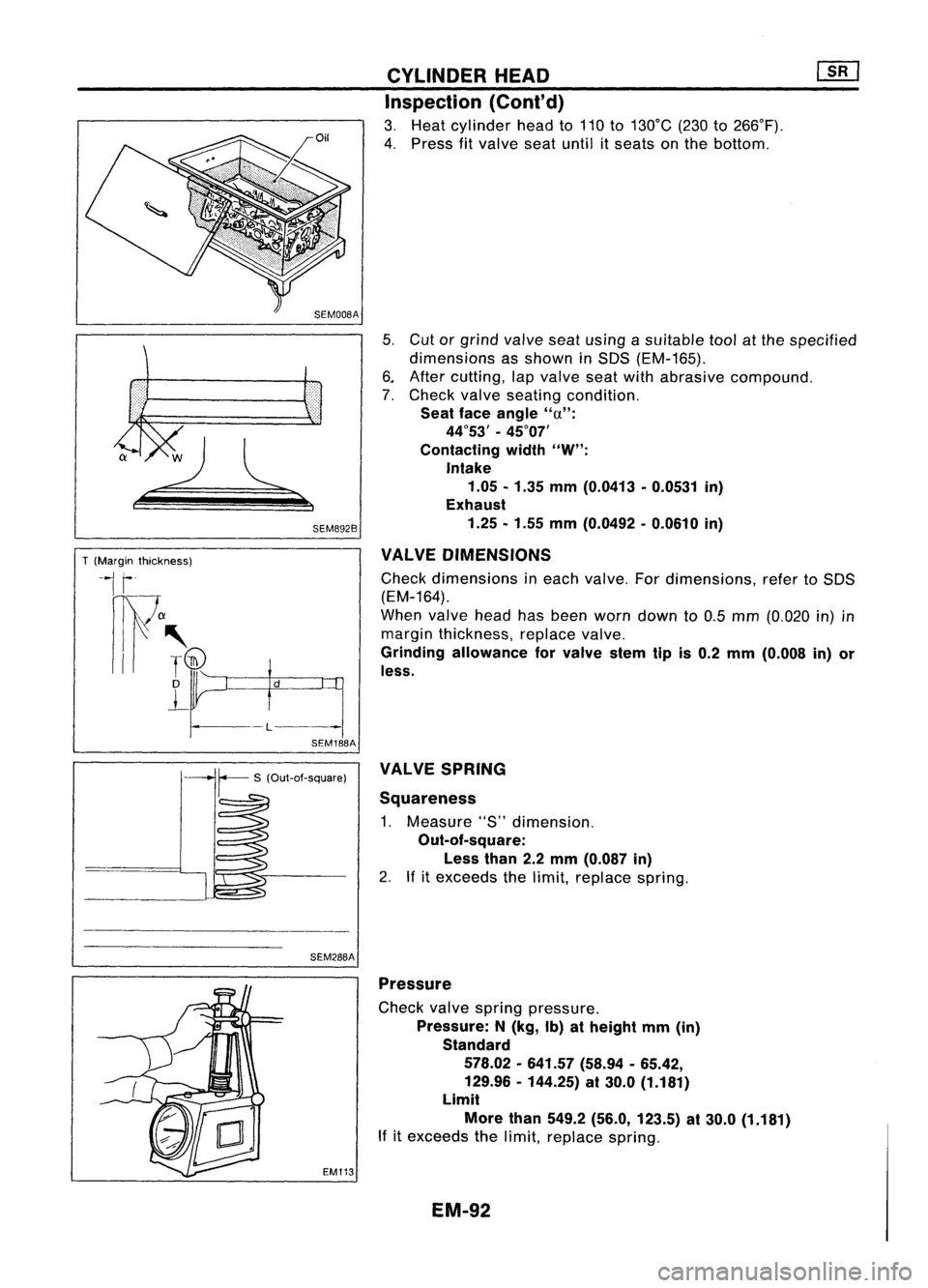
Seat faceangle
"u":
44°53' -45°07'
Contacting width
"W":
Intake 1.05 -1.35 mm(0.0413 -0.0531 in)
Exhaust
1.25 -1.55 mm(0.0492 -0.0610 in)
VALVE DIMENSIONS
Check dimensions ineach valve. Fordimensions, refertoSDS
(EM-164).
When valveheadhasbeen worn down to0.5 mm (0.020 in)in
margin thickness, replacevalve.
Grinding allowance forvalve stemtipis0.2 mm (0.008 in)or
less.
SEM288A VALVE
SPRING
Squareness
1. Measure "S"dimension.
Out-of-square:
Less than2.2mm (0.087 in)
2. Ifitexceeds thelimit, replace spring.
EM113 Pressure
Check valvespring pressure.
Pressure: N(kg, Ib)atheight mm(in)
Standard
578.02 -641.57 (58.94-65.42,
129.96 -144.25) at30.0 (1.181)
Limit
More than549.2 (56.0, 123.5) at30.0 (1.181)
If itexceeds thelimit, replace spring.
EM-92
Page 1315 of 1701
![NISSAN ALMERA N15 1995 Service Manual SEM202
SEM731BA
Grade number
Tightening sequence
r
1
@@
~.~.~
o
,..0
W
@
@ @
Facing frontofengine
(position 2)
SEM528DCYLINDER
HEAD
[£Q]
Inspection {Cont'd)
4. Remove cambracket capsan NISSAN ALMERA N15 1995 Service Manual SEM202
SEM731BA
Grade number
Tightening sequence
r
1
@@
~.~.~
o
,..0
W
@
@ @
Facing frontofengine
(position 2)
SEM528DCYLINDER
HEAD
[£Q]
Inspection {Cont'd)
4. Remove cambracket capsan](/manual-img/5/57349/w960_57349-1314.png)
SEM202
SEM731BA
Grade number
Tightening sequence
r
1
@@
~.~.~
o
,..0
W
@
@ @
Facing frontofengine
(position 2)
SEM528DCYLINDER
HEAD
[£Q]
Inspection {Cont'd)
4. Remove cambracket capsandmeasure maximum widthof
plastigage. Camshaft bearingclearance:
Limit
0.1 mm (0.004 in)
5. Ifclearance appearstoexceed thelimit, replace camshaft
or cylinder head.
• Which partstobe replaced shouldbedecided uponafter
measuring thediameters ofthe parts concerned.
Assembly
1. Install valvecomponent parts.
Install valvespring withitsnarrow pitchsidetoward cylinder
head side.
• Always installnewvalve oilseals.
Refer tooil seal replacement.
• Before installing oilseal, install valve-spring seat.
• When installing valve,applyengine oilonthe valve stem
and lipofvalve oilseal.
• Check whether thevalve faceisfree from foreign matter.
• Install valvespring retainers onthe intake sideandvalve
rotators onthe exhaust side.
• Valve rotators cannotbedisassembled.
2. Install camshaft andbrackets andtighten bracket nutstothe
specified torqueintwo orthree stages.
Camshaft-bracket nuts:
~: 18-22 N'm (1.8-2.2 kg-m, 13-16 ft-Ib)
• Tighten bracketfromcenter tooutside.
• Apply sealant tobrackets No.1and No.5.
• When installing "brackets, setcamshaft sothat thepinof
camshaft fronthead isuppermost.
• Install newcamshaft oilseals.
Refer tooil seal replacement.
17.5 (0.689)
o
o
13.0
(0.512)
NO.1 journal bracket No.5journal bracket
Unit: mm(in)
SEM676D
EM-136
Page 1344 of 1701
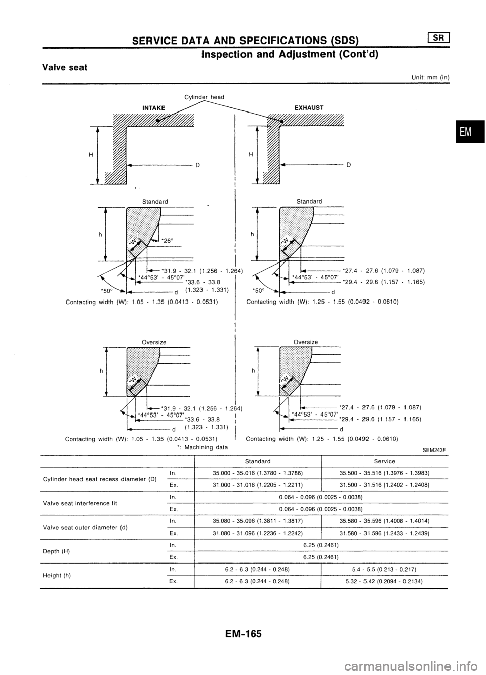
SERVICEDATAANDSPECIFICATIONS (SOS)
Inspection andAdjustment (Cont'd)
Valve seat
Unit:mm(in)
Cylinder head
•
H H
4
D D
Standard Standard
h '26°
I
I
I
'31.9 -32.1 (1.256 -1.264)
'44°53' -45°01'
'33.6-338
d (1.323 -1.331)
Contacting width(W):1.05-1.35 (0.0413 -0.0531) '27.4
-27.6 (1.079 -1.087)
'29.4 -29.6 (1.157 -1.165)
'50° d
Contacting width(W):125-1.55 (0.0492 -0.0610)
Oversize Oversize
'31.9 -321 (1.256 -1.264)
'44°53' -45°01', I
33.6 -33.8 I
d (1.323 -1.331)
I
Contacting width(W):1.05-1.35 (00413 -0.0531)
': Machining data h
-'27.4 -27.6 (1.079 -1.087)
'44°53' -45°01'
'29.4-29.6 (1.157 -1.165)
d
Contacting width(W):1.25-1.55 (0.0492 -0.0610)
SEM243F
Standard Service
In. 35000-35.016 (1.3780 -1.3786) 35500-35.516 (1.3976 -1.3983)
Cylinder headseatrecess diameter (D)
Ex. 31.000
-31.016 (1.2205 -1.2211) 31.500-31.516 (1.2402 -1.2408)
In. 0.064-0.096 (0.0025 -0.0038)
Valve seatinterference fit
Ex. 0.064
-0.096 (0.0025 -0.0038)
In. 35.080-35.096 (1.3811 -1.3817) 35.580-35.596 (1.4008 -1.4014)
Valve seatouter diameter (d)
Ex.31.080-31.096 (1.2236 -1.2242) 31.580-31.596 (1.2433 -1.2439)
In. 6.25(0.2461)
Depth (H)
Ex. 6.25(0.2461)
In. 62-63 (0.244 -0.248) 5.4-5.5 (0.213 -0.217)
Height (h)
Ex.6.2-6.3 (0.244 -0.248) 532-5.42 (0.2094 -0.2134)
EM-165
Page 1349 of 1701
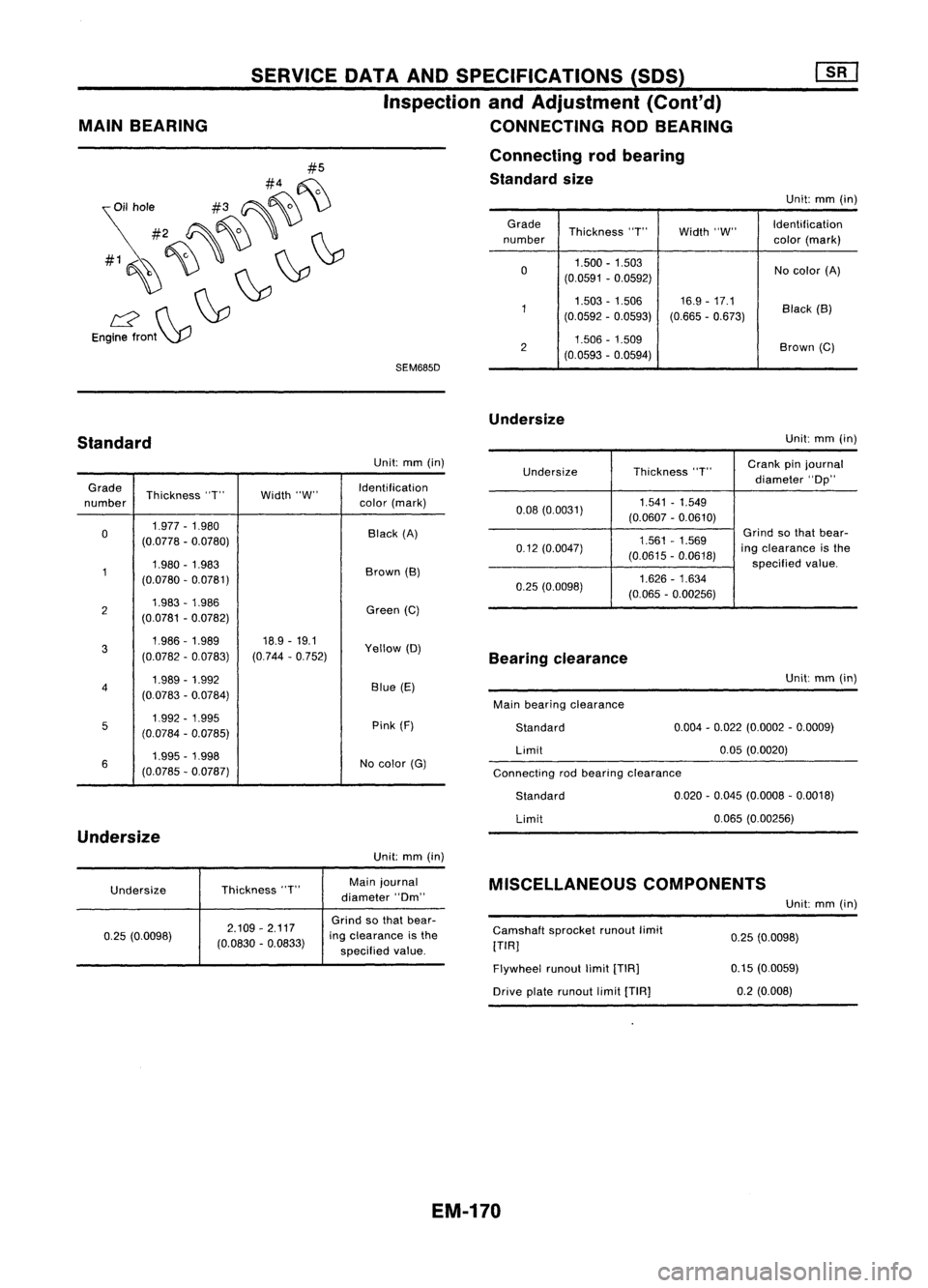
SEM685D
#5
#4 ~
~il hole #3~~ \)
#2 ~~'
#1~~~ ~~
L2 ~~
Engine front~
MAIN
BEARING SERVICE
DATAANDSPECIFICATIONS (SOS)
Inspection andAdjustment (Cont'd)
CONNECTING RODBEARING
Connecting rodbearing
Standard size
Unit:mm(in)
Grade Thickness"T"Width"W" Identification
number color(mark)
0 1.500
-1.503
Nocolor (A)
(0.0591 -0.0592)
1 1.503
-1.506 16.9-17.1
Black(B)
(0.0592 -0.0593) (0.665-0.673)
2 1.506
-1.509
Brown(C)
(0.0593 -0.0594)
Undersize
Standard
Unit:
mm(in)
Connecting rodbearing clearance
Undersize
Thickness
"T"
Crank
pinjournal
diameter "Op"
0.08 (0.0031) 1.541
-1.549
(0.0607 -0.0610)
1.561 -1.569
Grind
sothat bear-
0.12 (0.0047)
(0.0615-0.0618)
ing
clearance isthe
specified value.
0.25 (0.0098) 1.626
-1.634
(0.065 -0.00256)
Unit:
mm(in)
Grade Thickness "T"Width"W" Identification
number color
(mark)
0 1.977
-1.980
Black(A)
(0.0778 -0.0780)
1 1.980
-1.983
Brown(B)
(0.0780 -0.0781)
2 1.983
-1.986
Green(C)
(0.0781 -0.0782)
3 1.986-1.989
18.9-19.1
Yellow(D)
(0.0782 -0.0783) (0.744
-0.752)
4 1.989
-1.992
Blue(E)
(0.0783 -0.0784)
5 1.992
-1.995
Pink(F)
(0.0784 -0.0785)
6 1.995
-1.998
Nocolor (G)
(0.0785 -0.Q787)
Undersize
Unit:mm(in)
Bearing
clearance
Main bearing clearance
Standard
Limit
Standard
Limit Unit:
mm(in)
0.004 -0.022 (0.0002 -0.0009)
0.05 (0.0020)
0.020 -0.045 (0.0008 -0.0018)
0.065 (0.00256)
Undersize Thickness
"T" Main
journal
diameter "Om"
MISCELLANEOUS
COMPONENTS
Unit:mm(in)
0.25 (0.0098) 2.109
-2.117
(0.0830 -0.0833)
Grind
sothat bear-
ing clearance isthe
specified value. Camshaft
sprocketrunoutlimit
[TIR]
Flywheel runoutlimit[TIR]
Drive platerunout limit[TIA]
0.25
(0.0098)
0.15 (0.0059)
0.2 (0.008)
EM-170
Page 1354 of 1701
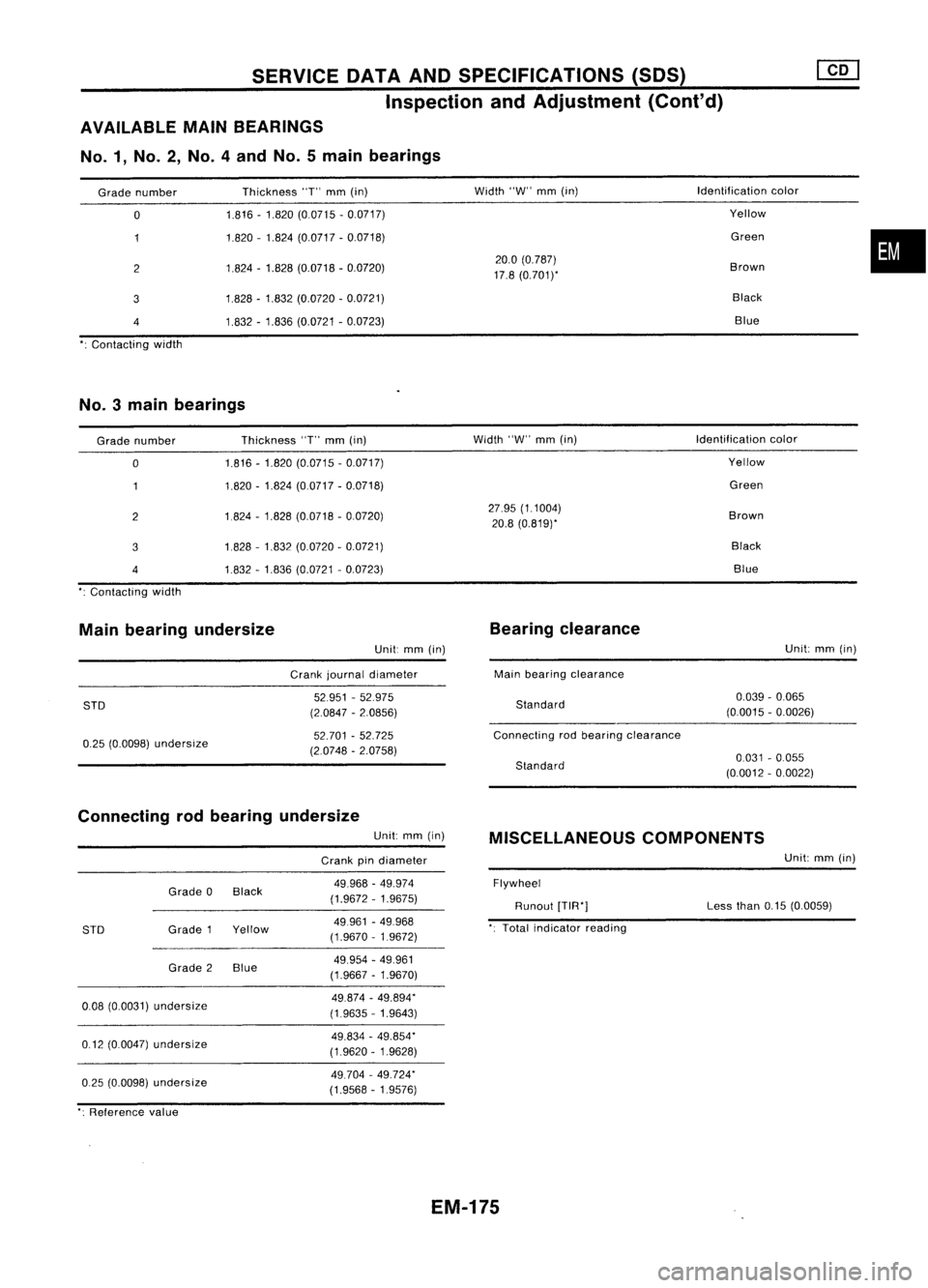
SERVICEOATAAND SPECIFICATIONS (SOS)
Inspection andAdjustment (Cont'd)
AVAILABLE MAINBEARINGS
No.1, No.2, No.4andNo.5main bearings
Grade number
o
2
3
4
Contacting width Thickness
"T"
mm
(in)
1.816 -1.820 (0.0715 -0.0717)
1.820 -1.824 (0.0717 -0.0718)
1.824 -1.828 (0.0718 -0.0720)
1.828 -1.832 (0.0720 -0.0721)
1.832 -1.836 (0.0721 -0.0723)
Width
"W"
mm
(in)
20.0 (0.787)
17.8 (0.7011'
Identification
color
Yellow
Green
Brown Black Blue
•
No.3 mainbearings
Grade number
o
2
3
4
Contacting width Thickness
"T"
mm
(in)
1.816 -1.820 (0.0715 -0.0717)
1.820 -1.824 (0.0717 -0.0718)
1.824 -1.828 (0.0718 -0.0720)
1828 -1.832 (0.0720 -0.0721)
1.832 -1.836 (0.0721 -0.0723)
Width
"W"
mm
(in)
27.95 (1.1004)
20.8 (0.819)'
Identification
color
Yellow
Green
Brown BlackBlue
Main bearing undersize
Unit:
mm
(in)
Crank journal diameter
Bearing
clearance
Main bearing clearance Unit:
mm
(in)
STD
0.25 (0.0098)
undersize
52951
-52.975
(2.0847 -2.0856)
52.701 -52.725
(2.0748 -2.0758)
Standard
Connecting rodbearing clearance
Standard
0.039
-0.065
(0.0015 -0.0026)
0.031 -0.055
(0.0012 -0.0022)
Connecting rodbearing undersize
Unit:
mm
(in)
Crank pindiameter
MISCELLANEOUS
COMPONENTS
Unit:
mm
(in)
0.25 (0.0098)
undersize
0.08
(0.0031)
undersize
0.12 (0.0047)
undersize
STD
Grade
0Black
Grade 1Yellow
Grade 2Blue
49.968
-49.974
(1.9672 -1.9675)
49961 -49.968
(1.9670 -1.9672)
49.954 -49.961
(1.9667 -1.9670)
49.874 -49.894"
(1.9635 -1.9643)
49.834 -49.854"
(1.9620 -1.9628)
49.704 -49.724"
(1.9568 -1.9576)
Flywheel
Runout
[TIR"]
Total indicator reading Less
than
0.15(0.0059)
": Reference value
EM-175