Page 1481 of 1701
Pulleyassembly SERVICE
PROCEDURES
Compressor Clutch(Cont'd)
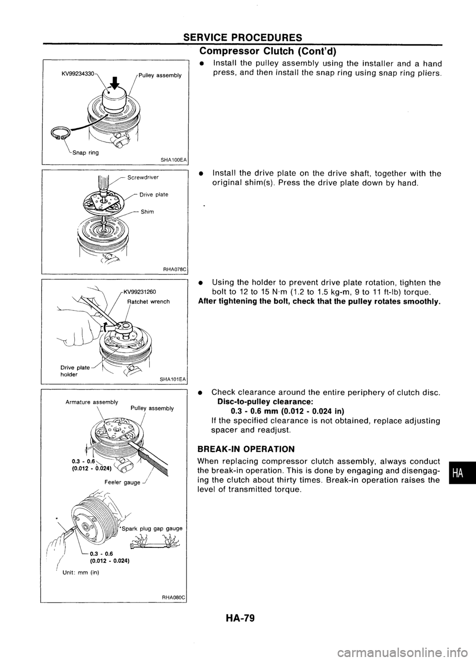
• Install thepulley assembly usingtheinstaller andahand
press, andthen install thesnap ringusing snapring
pliers.
SHA100EA
•Install thedrive plateonthe drive shaft, together withthe
original shim(s). Pressthedrive platedown byhand.
Drive plate
-Shim
RHA07BC
•Using theholder toprevent driveplaterotation, tightenthe
bolt to12to15 N'm (1.2to1.5 kg-m, 9to 11ft-Ib) torque.
After tightening thebolt, check thatthepulley rotates smoothly.
• Check clearance aroundtheentire periphery ofclutch disc.
Disc-to-pulley clearance:
0.3 -0.6 mm (0.012 -0.024 in)
If the specified clearance isnot obtained, replaceadjusting
spacer andreadjust.
BREAK-IN OPERATION
When replacing compressor clutchassembly, alwaysconduct •
the break-in operation. Thisisdone byengaging anddisengag-
i
ing the clutch aboutthirtytimes. Break-in operation raisesthe
level oftransmitted torque.
SHA101EA
Pulley assembly
/
Feeler gauge
-.I
-~~ 'Sparkpluggapgauge
~
Drive
plate
holder
(
Unit:mm(in)
RHAOBOCHA-79
Page 1482 of 1701
SERVICEPROCEDURES
Thermal Protector
INSPECTION
• When servicing, donot allow foreign mattertoget into com-
pressor.
• Check continuity betweentwoterminals.
Compressor -Model CR-14(Calsonic make)
Pulley assembly
Snap ring
Clutch disc
Center bolt~12 -
15 N.m
(1.2-1.5 kg-m, 9-
11 ft-Ib)
RHA314E
Compressor Clutch
REMOVAL
• When removing centerbolt,holdclutch discwithclutch disc
wrench.
• Take offclutch disc.
• Remove snapring(which secures rotorpulley) byusing
external snapringpliers.
HA-80
Page 1483 of 1701
RHA317ESERVICE
PROCEDURES
Compressor Clutch(Cont'd)
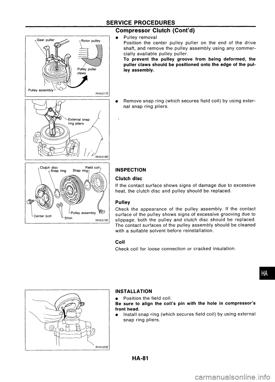
• Pulley removal
Position thecenter pulleypulleronthe end ofthe drive
shaft, andremove thepulley assembly usinganycommer-
cially available pulleypuller.
To prevent thepulley groove frombeing deformed, the
puller clawsshould bepositioned ontotheedge ofthe pul-
ley assembly.
~~
\t
PUlleyassembly
-Shim RHA319E
RHA320E
•
Remove snapring(which secures fieldcoil)byusing exter-
nal snap ringpliers.
INSPECTION
Clutch disc
If the contact surface showssignsofdamage duetoexcessive
heat, theclutch discandpulley should bereplaced.
Pulley
Check theappearance ofthe pulley assembly. Ifthe contact
surface ofthe pulley shows signsofexcessive groovingdueto
slippage, boththepulley andclutch discshould bereplaced.
The contact surfaces ofthe pulley assembly shouldbecleaned
with asuitable solventbeforereinstallation.
Coil
Check coilforloose connection orcracked insulation .
INSTALLATION
• Position thefield coil.
Be sure toalign thecoil's pinwith thehole incompressor's
front head.
• Install snapring(which secures fieldcoil)byusing external
snap ringpliers.
HA-81
•
Page 1484 of 1701
KV99106800
~ RHA321EA
~
s~
~ Clutchdisc
SERVICE
PROCEDURES
Compressor Clutch(Cont'd)
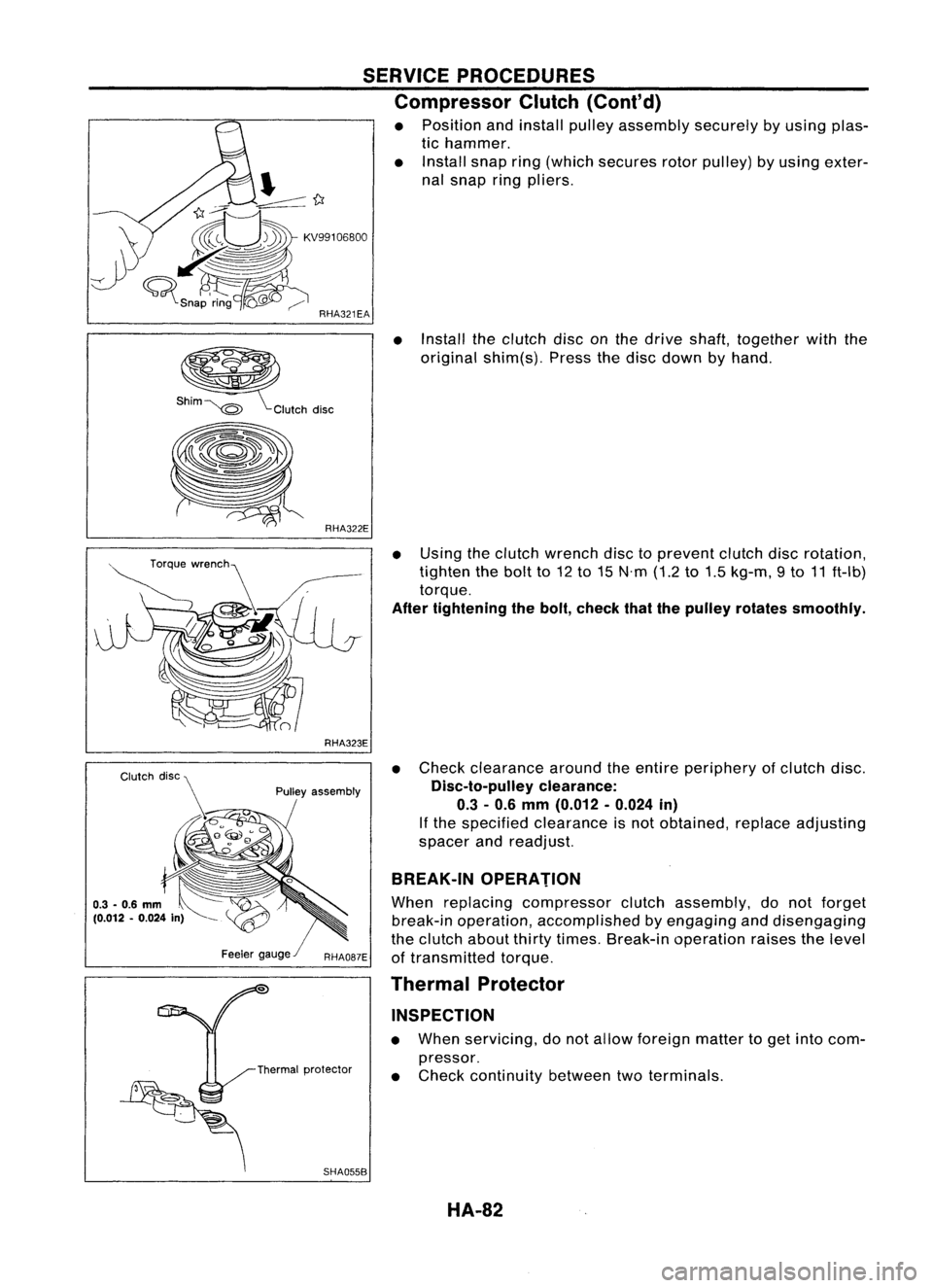
• Position andinstall pulleyassembly securelybyusing plas-
tic hammer.
• Install snapring(which secures rotorpulley) byusing exter-
nal snap ringpliers.
• Install theclutch disconthe drive shaft, together withthe
original shim(s). Pressthedisc down byhand.
RHA323E
Pulley assembly
SHA055B
•
Using theclutch wrench disctoprevent clutchdiscrotation,
tighten thebolt to12 to15 N'm (1.2to1.5 kg-m, 9to 11ft-Ib)
torque.
After tightening thebolt, check thatthepulley rotates smoothly.
• Check clearance aroundtheentire periphery ofclutch disc.
Disc-to-pulley clearance:
0.3 -0.6 mm (0.012 -0.024 in)
If the specified clearance isnot obtained, replaceadjusting
spacer andreadjust.
BREAK-IN OPERATION
When replacing compressor clutchassembly, donot forget
break-in operation, accomplished byengaging anddisengaging
the clutch aboutthirtytimes. Break-in operation raisesthelevel
of transmitted torque.
Thermal Protector
INSPECTION
• When servicing, donot allow foreign mattertoget into com-
pressor.
• Check continuity betweentwoterminals.
HA-82
Page 1486 of 1701
COMPRESSOR SERVICE
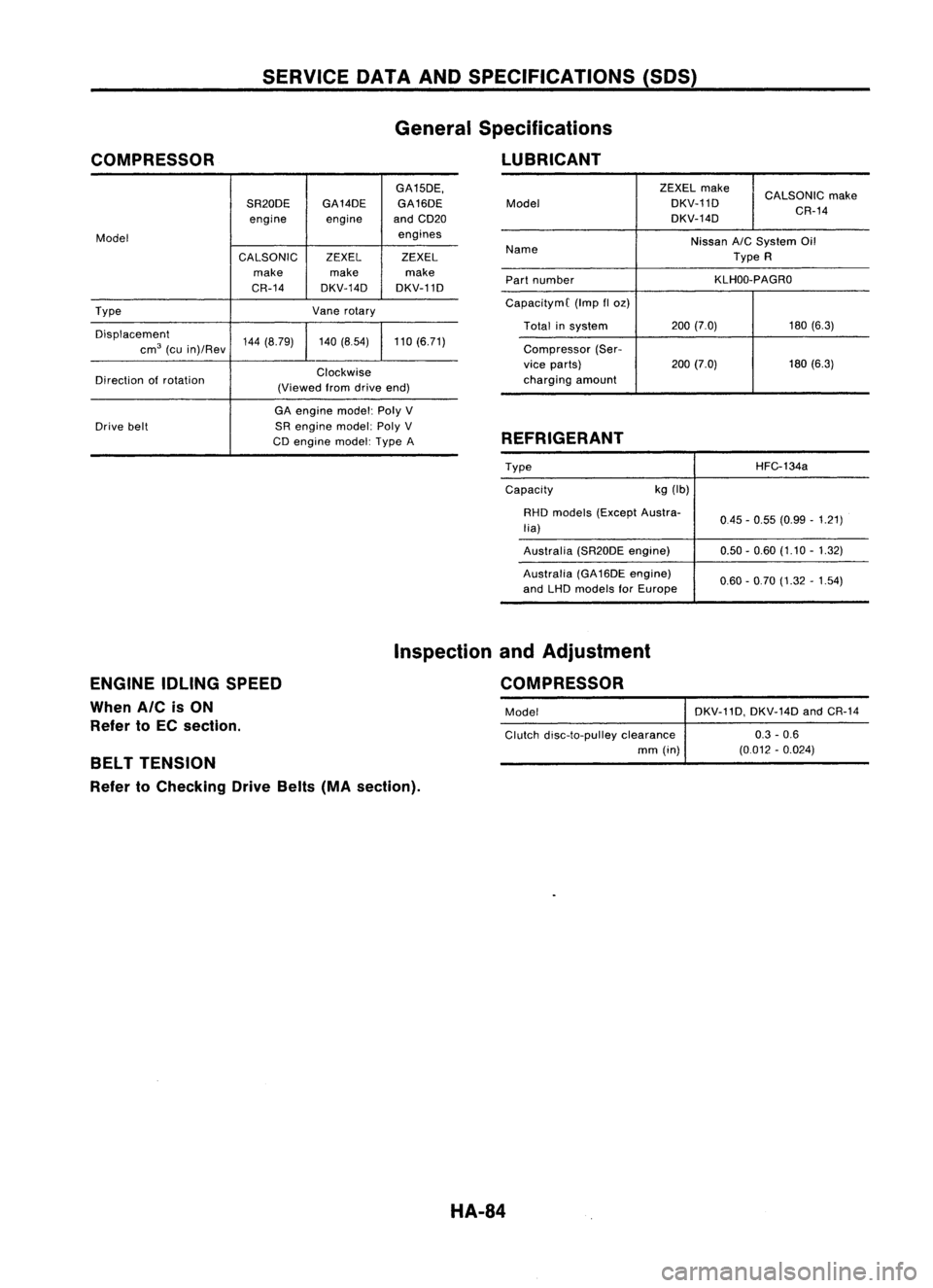
DATAANDSPECIFICATIONS (50S)
General Specifications
LUBRICANT
GA15DE,
SR20DE GA14DE
GA16DE
engine engineandCD20
Model engines
CALSONIC ZEXELZEXEL
make makemake
CR-14 DKV-14D DKV-11D
Type Vanerotary
Displacement 144(8.79) 140(8.54) 110(6.71)
cm
3
(cuin)/Rev
Direction ofrotation Clockwise
(Viewed fromdrive end)
GA engine model:PolyV
Drive belt SRengine model:PolyV
CD engine model:TypeA ZEXEL
make
CALSONIC make
Model DKV-11D
DKV-14D CR-14
Name Nissan
A/C
System Oil
Type R
Part number KLHOO-PAGRO
CapacitymC (Impfloz)
Total insystem 200
(7.0) 180(6.3)
Compressor (Ser-
vice parts) 200(7.0) 180
(6.3)
charging amount
REFRIGERANT
TypeCapacity kg
(Ib) HFC-134a
RHD models (Except Austra-
lia)
Australia (SR20DEengine)
Australia (GA16DE engine)
and LHD models forEurope 0.45
-0.55 (0.99 -1.21)
0.50 -0.60 (1.10 -1.32)
0.60 -0.70 (1.32 -1.54)
ENGINE IDLINGSPEED
When AICisON
Refer toEC section. Inspection
andAdjustment
COMPRESSOR
Model DKV-11D,DKV-14DandCR-14
Clutch disc-to-pulley clearance 0.3-0.6
mm (in) (0.012-0.024)
BELT TENSION
Refer toChecking DriveBelts(MAsection).
HA-84
Page 1488 of 1701
CONTENTS(Cont'd.)
CHASSIS ANDBODY MAINTENANCE 45
Checking ExhaustSystem .45
Checking ClutchFluidLevel andLeaks .45
Checking ClutchSystem .45
Checking MfTOil .45
Changing MfTOil 46
Checking
AfT
Fluid Level .46
Changing
AfT
Fluid .47
Checking BrakeFluidLevel andLeaks 47
Checking BrakeSystem .47
Changing BrakeFluid .47
Checking BrakeBooster, VacuumHoses,
Connections andCheck Valve ~48
Checking DiscBrake .48
Checking DrumBrake .49
Balancing Wheels 49
Ti re Rotation 50
Checking SteeringGearandLinkage 50
Checking PowerSteering FluidandLines 50
Lubricating Locks,Hinges andHood Latches 51
Checking SeatBelts, Buckles, Retractors,
Anchors andAdjusters 51
Checking BodyCorrosion 52
GA
SERVICE DATAANDSPECIFICATIONS
(505)53
Engine Maintenance 53
SR
SERVICE DATAANDSPECIFICATIONS
(505)54
Engine Maintenance 54
CD
SERVICE DATAANDSPECIFICATIONS
(505)55
Engine Maintenance 55
SERVICE DATAANDSPECIFICATIONS
(505)56
Chassis andBody Maintenance 56
Page 1491 of 1701
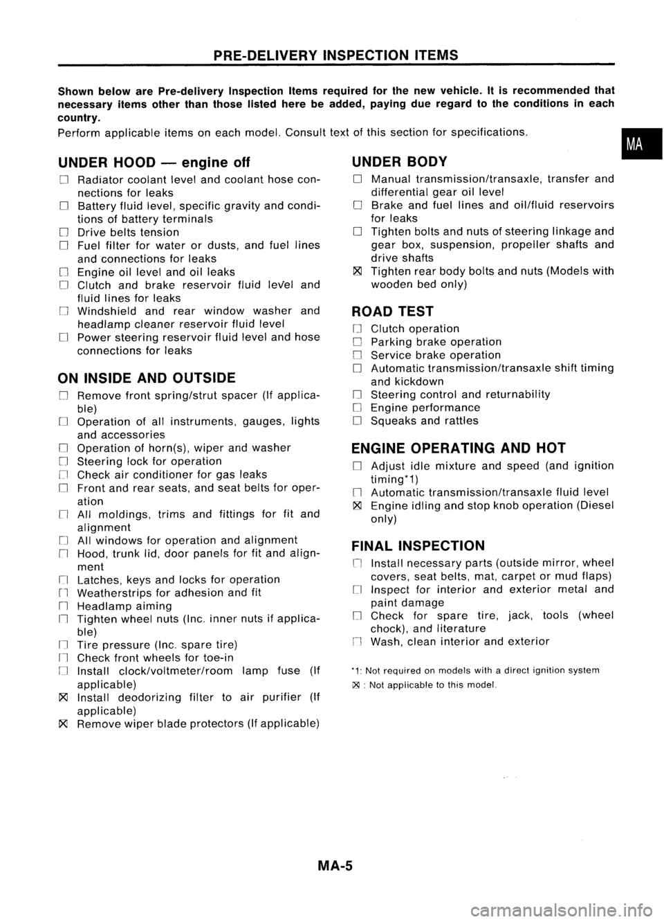
PRE-DELIVERYINSPECTIONITEMS
Shown belowarePre-delivery InspectionItemsrequired forthe new vehicle. Itis recommended that
necessary itemsotherthanthose listedherebeadded, payingdueregard tothe conditions ineach
country.
Perform applicable itemsoneach model. Consult textofthis section forspecifications .
UNDER HOOD-engine off
o
Radiator coolantlevelandcoolant hosecon-
nections forleaks
o
Battery fluidlevel, specific gravityandcondi-
tions ofbattery terminals
o
Drive beltstension
D
Fuel filter forwater ordusts, andfuel lines
and connections forleaks
[] Engine oillevel andoilleaks
D
Clutch andbrake reservoir fluidlevel and
fluid lines forleaks
o
Windshield andrear window washerand
headlamp cleanerreservoir fluidlevel
D
Power steering reservoir fluidlevel andhose
connections forleaks
ON INSIDE ANDOUTSIDE
D
Remove frontspring/strut spacer(Ifapplica-
ble)
D
Operation ofall instruments, gauges,lights
and accessories
o
Operation ofhorn(s), wiperandwasher
[] Steering lockforoperation
[] Check airconditioner forgas leaks
o
Front andrear seats, andseat belts foroper-
ation
n
All moldings, trimsandfittings forfitand
alignment
[J
Allwindows foroperation andalignment
n
Hood, trunklid,door panels forfitand align-
ment
[1
Latches, keysandlocks foroperation
rl
Weatherstrips foradhesion andfit
[l
Headlamp aiming
I~ Tighten wheelnuts(Inc. inner nutsifapplica-
ble)
IJ Tire pressure (Inc.spare tire)
Il
Check frontwheels fortoe-in
IJ Install clock/voltmeter/room lampfuse(If
applicable)
~ Install deodorizing filtertoair purifier (If
applicable)
~ Remove wiperbladeprotectors (Ifapplicable)
UNDER
BODY
o
Manual transmission/transaxle, transferand
differential gearoillevel
D
Brake andfuel lines andoil/fluid reservoirs
for leaks
D
Tighten boltsandnuts ofsteering linkageand
gear box,suspension, propellershaftsand
drive shafts
~ Tighten rearbody boltsandnuts (Models with
wooden bedonly)
ROAD TEST
D
Clutch operation
D
Parking brakeoperation
[J
Service brakeoperation
D
Automatic transmission/transaxle shifttiming
and kickdown
[] Steering controlandreturnability
o
Engine performance
D
Squeaks andrattles
ENGINE OPERATING ANDHOT
D
Adjust idlemixture andspeed (andignition
timing*1)
n
Automatic transmission/transaxle fluidlevel
~ Engine idlingandstop knob operation (Diesel
only)
FINAL INSPECTION
n
Install necessary parts(outside mirror,wheel
covers, seatbelts, mat,carpet ormud flaps)
[1
Inspect forinterior andexterior metaland
paint damage
[] Check forspare tire,jack, tools (wheel
chock), andliterature
n
Wash, cleaninterior andexterior
"1: Not required onmodels withadirect ignition system
~ :Not appiicable tothis model.
•
MA-5
Page 1492 of 1701
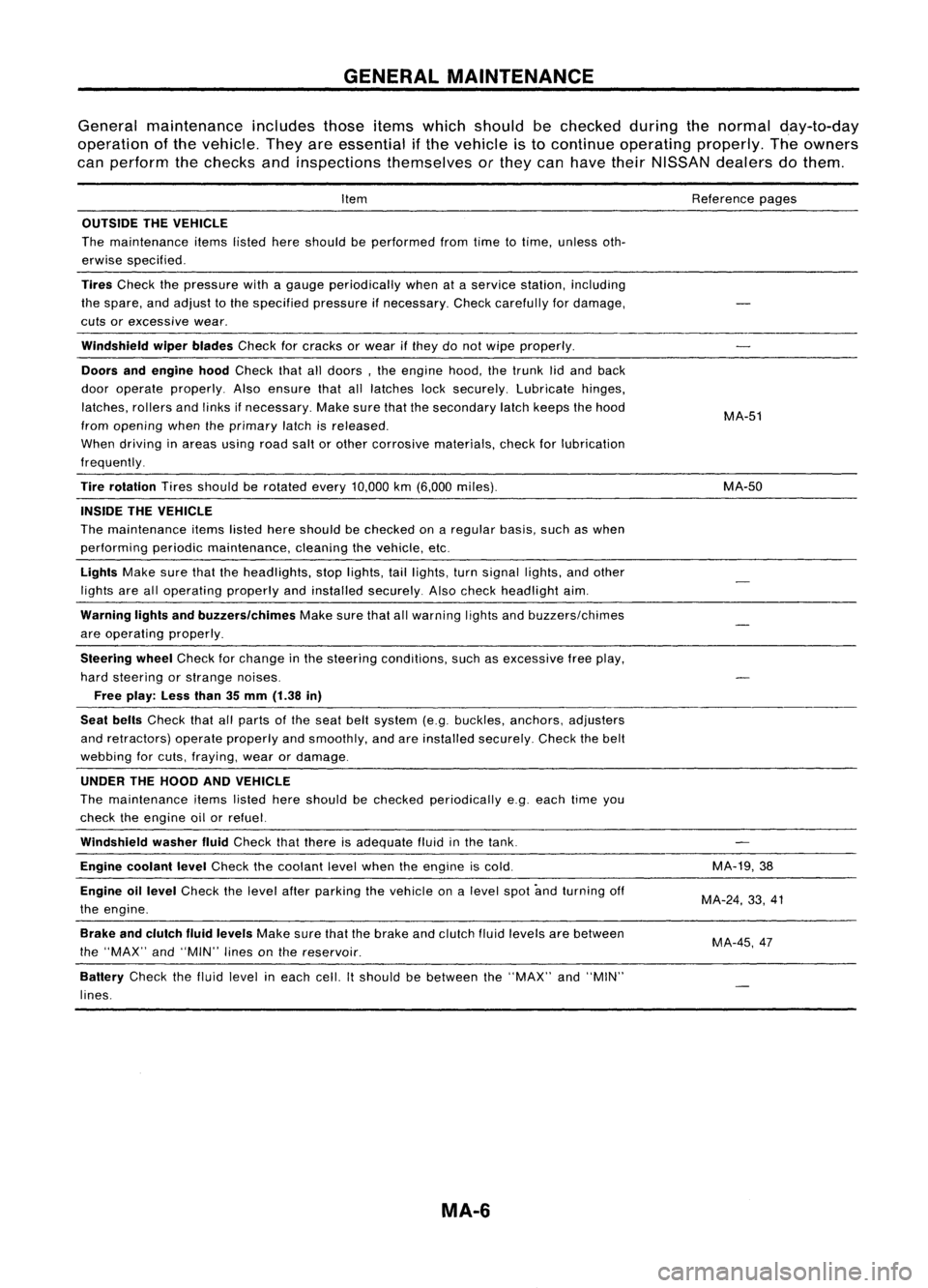
GENERALMAINTENANCE
General maintenance includesthoseitemswhich should bechecked duringthenormal day-to-day
operation ofthe vehicle. Theyareessential ifthe vehicle isto continue operating properly.Theowners
can perform thechecks andinspections themselves orthey canhave theirNISSAN dealersdothem.
Item
OUTSIDE THEVEHICLE
The maintenance itemslistedhereshould beperformed fromtimetotime, unless oth-
erwise specified.
Tires
Check thepressure withagauge periodically whenataservice station, including
the spare, andadjust tothe specified pressureifnecessary. Checkcarefully fordamage,
cuts orexcessive wear.
Windshield wiperblades
Checkforcracks orwear ifthey donot wipe properly.
Doors andengine hood
Check thatalldoors, theengine hood,thetrunk lidand back
door operate properly. Alsoensure thatalllatches locksecurely. Lubricate hinges,
latches, rollersandlinks ifnecessary. Makesurethatthesecondary latchkeeps thehood
from opening whentheprimary latchisreleased.
When driving inareas usingroadsaltorother corrosive materials, checkforlubrication
frequently.
Tire rotation
Tiresshould berotated every
10,000
km
(6,000
miles).
INSIDE THEVEHICLE
The maintenance itemslistedhereshould bechecked onaregular basis,suchaswhen
performing periodicmaintenance, cleaningthevehicle, etc.
Lights
Makesurethattheheadlights, stoplights, taillights, turnsignal lights,andother
lights arealloperating properlyandinstalled securely. Alsocheck headlight aim.
Warning lightsandbuzzers/chimes
Makesurethatallwarning lightsandbuzzers/chimes
are operating properly.
Steering wheel
Check forchange inthe steering conditions, suchasexcessive freeplay,
hard steering orstrange noises.
Free play: Lessthan35mm (1.38 in)
Seat belts
Check thatallparts ofthe seat beltsystem (e.g.buckles, anchors, adjusters
and retractors) operateproperly andsmoothly, andareinstalled securely. Checkthebelt
webbing forcuts, fraying, wearordamage.
UNDER THEHOOD ANDVEHICLE
The maintenance itemslisted hereshould bechecked periodically e.g.each timeyou
check theengine oilorrefuel.
Windshield washerfluid
Check thatthere isadequate fluidinthe tank.
Engine coolant level
Check thecoolant levelwhen theengine iscold.
Engine oillevel
Check thelevel afterparking thevehicle onalevel spotandturning off
the engine.
Brake andclutch fluidlevels
Makesurethatthebrake andclutch fluidlevels arebetween
the "MAX" and"MIN" linesonthe reservoir.
Battery
Checkthefluid level ineach cell.Itshould bebetween the"MAX" and"MIN"
lines.
MA-6
Reference
pages
MA-51
MA-50
MA-19,38
MA-24, 33,41
MA-45,47