1995 NISSAN ALMERA N15 clutch
[x] Cancel search: clutchPage 412 of 1701
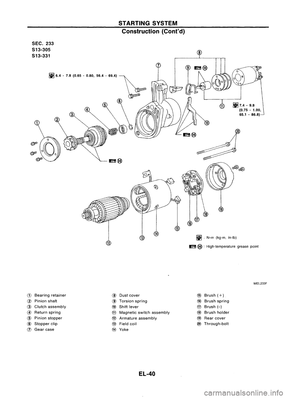
STARTINGSYSTEM
Construction (Cont'd)
5EC. 233
513-305
513-331
Iil!J
'.4 .7.8 (0.'5 -0.80, 56.4-88.4) ~
6
8
~7.4.9.8
(0.75 -1.00,
65.1 -86.8)
~ .N.m (kg-m, in-Ib)
m
@:
High-temperature greasepoint
MEL233F
CD
Bearing retainer
@
Pinion shaft
@
Clutch assembly
@
Return spring
@
Pinion stopper
@
Stopper clip
(J)
Gear case
@
Dust cover
@
Torsion spring
@)
Shift lever
@
Magnetic switchassembly
@
Armature assembly
@
Field coil
@
Yoke
EL-40 @
Brush
(+)
@)
Brush spring
@
Brush
H
@
Brush holder
@
Rear cover
@)
Through-bolt
Page 418 of 1701
Type1
Type 2
Type
3
W4
Type 1 Type
2 STARTING
SYSTEM
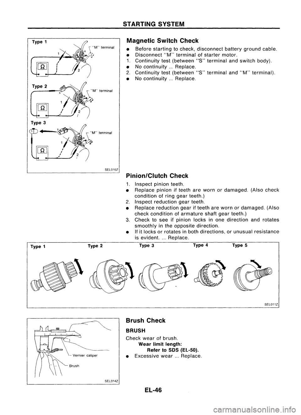
Magnetic SwitchCheck
• Before starting tocheck, disconnect batterygroundcable.
• Disconnect "M"terminal ofstarter motor.
1. Continuity test(between "S"terminal andswitch body).
• Nocontinuity ...Replace.
2. Continuity test(between "S"terminal and"M" terminal).
• Nocontinuity ...Replace.
Pinion/Clutch Check
1. Inspect pinionteeth.
• Replace pinionifteeth areworn ordamaged. (Alsocheck
condition ofring gear teeth.)
2. Inspect reduction gearteeth.
• Replace reduction gearifteeth areworn ordamaged. (Also
check condition ofarmature shaftgearteeth.)
3. Check tosee ifpinion locksinone direction androtates
smoothly inthe opposite direction.
• If
it locks orrotates inboth directions, orunusual resistance
is evident. ...Replace.
Type 3 Type4 Type5
- Vernier caliper
SEL014Z SEL011Z
Brush Check
BRUSH
Check wearofbrush.
Wear limitlength:
Refer to50S (El-SO).
• Excessive wear...Replace.
EL-46
Page 721 of 1701
CONTENTS(Cont'd.)
CONSULT Reference ValueinData Monitor
Mode 74
Major Sensor Reference GraphinData
Monitor Mode 76
ECM Terminals andReference Value 78
TROUBLE DIAGNOSIS FORPOWER SUPPLY 88
Main Power Supply andGround Circuit.. 88
TROUBLE DIAGNOSIS FORDTC11 94
Camshaft PositionSensor(CMPS) 94
TROUBLE DIAGNOSIS FORDTC
12 101
Mass AirFlow Sensor (MAFS) 101
TROUBLE DIAGNOSIS FORDTC
13 108
Engine Coolant Temperature Sensor(ECTS) 108
TROUBLE DIAGNOSIS FORDTC
21 113
Ignition Signal 113
TROUBLE DIAGNOSIS FORDTC
34 119
Knock Sensor (KS) 119
TROUBLE DIAGNOSIS FORDTC
41 124
Intake AirTemperature Sensor(IATS) 124
TROUBLE DIAGNOSIS FORNON-DETECTABLE
ITEMS , '"
.128
Throttle Position Sensor 128
Vehicle SpeedSensor (VSS) 133
Start Signal 138
Injector 141
Fuel Pump 145
Idle AirControl Valve(IACV) -Auxiliary Air
Control (AAC)Valve 150
Cooling FanControl 156
Power Steering OilPressure Switch 169
Park/Neutral PositionSwitch 173
EVAP Canister PurgeControl Solenoid Valve179
EGR Valve andEVAP Canister PurgeControl
Solenoid Valve 183
Heated Oxygen Sensor(H02S) 189
Oxygen Sensor(02S) 194
Valve Timing Control (VTC) 198
IACV-FICD SolenoidValve 204
Electrical LoadSignal 211
Torque Converter ClutchSolenoid Valve 219
MIL
&
Data LinkConnectors 223
SR
ENGINE ANDEMISSION CONTROL OVERALL
SYSTE M
226
Circuit Diagram 226
System Diagram 227
ECCS Component PartsLocation 228
Vacuum HoseDrawing 231
System Chart... 232
ENGINE
ANDEMISSION BASICCONTROL
SYSTEM DESCRiPTION
233
Multipart FuelInjection (MFI)System 233
Distributor Ignition
(01)
System 235
Air Conditioning CutControl 236
Fuel CutControl (atnoload
&
high engine
speed) 237
EVAPORATIVE EMISSIONSYSTEM
238
Description 238
Inspection 238
POSITIVE CRANKCASE VENTILATION
240
Description 240
Inspection 240
BASIC SERVICE
PROCEDURE 241
Fuel Pressure Release 241
Fuel Pressure Check 241
Fuel Pressure Regulator Check 242
Injector Removal andInstallation 242
Idle Speed/Ignition Timing/IdleMixtureRatio
Adjustment 243
ON-BOARD DIAGNOSTIC SYSTEMDESCRIPTION ..250
Malfunction IndicatorLamp(MIL) 250
CONSULT 254
TROUBLE DIAGNOSIS -General Description
264
Introduction 264
Work Flow 265
Description forWork Flow 266
Diagnostic Worksheet 267
Diagnostic TroubleCode(DTC) Chart 268
Fail-Safe Chart 270
Basic Inspection 271
Symptom MatrixChart. 274
CONSULT Reference ValueinData Monitor
Mode 277
Major Sensor Reference GraphinData
Monitor Mode 279
ECM"Terminals andReference Value 281
TROUBLE DIAGNOSIS FORPOWER SUPPLY
286
Main Power Supply andGround Circuit.. 286
TROUBLE DIAGNOSIS FORDTC
11 289
Camshaft PositionSensor(CMPS) 289
TROUBLE DIAGNOSIS FORDTC
12 293
Mass AirFlow Sensor (MAFS) 293
TROUBLE DIAGNOSIS FORDTC
13 297
Engine Coolant Temperature Sensor(ECTS) 297
TROUBLE DIAGNOSIS FORDTC
21 301
Ignition Signal 301
TROUBLE DIAGNOSIS FORDTC
34 306
Knock Sensor (KS) 306
Page 722 of 1701
CONTENTS(Cont'd.)
TROUBLE DIAGNOSIS FORDTC
43 309
Throttle Position Sensor 309
TROUBLE DIAGNOSIS FORNON-DETECTABLE
ITEMS
314
Vehicle SpeedSensor (VSS) 314
Start Signal 317
Exhaust GasRecirculation (EGR)Valveand
EVAP Canister PurgeControl 319
Injector 324
Fuel Pump 327
Idle AirControl Valve(IACV)-Air Regulator 332
Idle AirControl Valve(IACV) -Auxiliary Air
Control (AAC)Valve :335
Idle AirControl Valve(IACV)-FICD Solenoid
Valve '"339
Cooling FanControl 343
Power Steering OilPressure Switch 354
Park/Neutral PositionSwitch 357
Heated Oxygen Sensor(H02S) 362
Torque
Converter
ClutchSolenoid Valve 367
Malfunction IndicatorLamp(MIL)
&
Data Link
Connector (DLC)forCONSULT 370
CD
INJECTION SYSTEM
371
VE.TYPE INJECTION PUMP
372
Removal 372
Installation 373
Adjustment 374
INJECTION NOZZLE
376
Removal andInstallation 376
Disassembly 376
Inspection 377
Cleaning 377
Assembly 378
Test andAdjustment 379
FUEL
SYSTEM CHECK
381
Priming PumpCheck 381
Fuel CutSolenoid Valve 381
CRANKCASE VENTILATION SYSTEM
382
Ventilation Hose 382
ENGINE ANDEMISSION CONTROLOVERALL
SYSTEM
383
Component PartsLocation 383
System Diagram 384
Circuit Diagram ,385
System Chart. 386
TROUBLE DIAGNOSES
387
ECM Terminals andReference Values 387
Quick-glow System 390
Partial LoadAdvance (PLA)Control 399
Cooling FanControl 404
Air Conditioner CutControl 413
Fuel CutControl 416
GA
SERVICE DATAANDSPECIFICATIONS
(505).417
General Specifications 417
Inspection andAdjustment.. 417
SR
SERVICE DATAANDSPECIFICATIONS
(505).418
General Specifications 418
Inspection andAdjustment.. .418
CD
SERVICE DATAANDSPECIFICATIONS
(505).419
VE-type Injection Pump 419
Injection Nozzle 419
•
When youread wiring diagrams:
• Read GIsection, "HOWTOREAD WIRING DIAGRAMS" .
• See Elsection, "POWER SUPPLYROUTING" forpower distribution circuit.
When youperform troublediagnoses, readGIsection, "HOWTOFOllOW FLOWCHART INTROU-
BLE DIAGNOSES" and"HOW TOPERFORM EFFICIENT DIAGNOSIS FORANELECTRICAL INCIDENT".
Page 742 of 1701
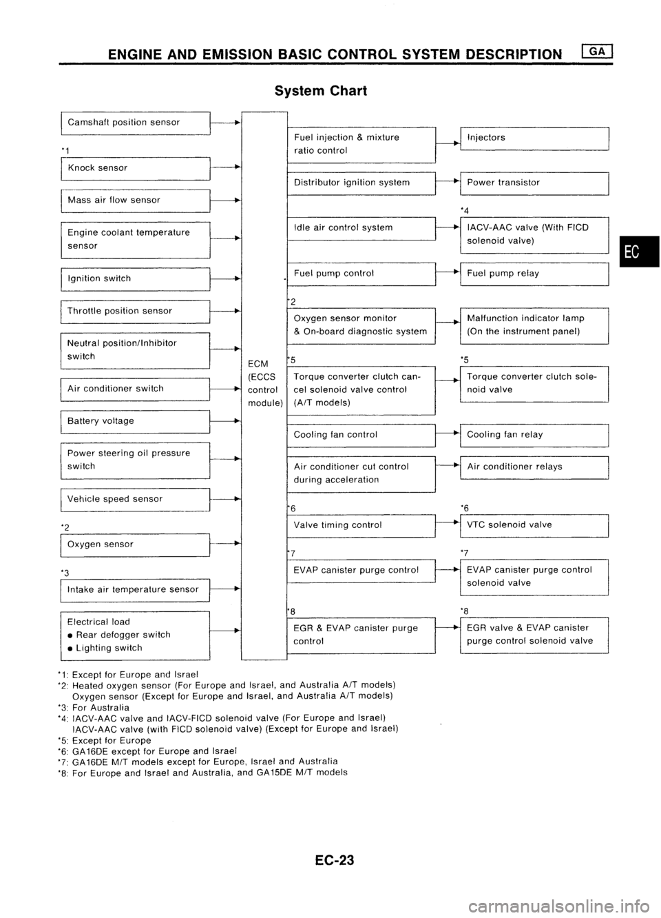
ENGINEANDEMISSION BASICCONTROL SYSTEMDESCRIPTION
System Chart
I
Camshaft positionsensor
'1
Fuel
injection
&
mixture
ratio control Injectors
Knock sensor
Distributorignitionsystem Powertransistor
Mass airflow sensor
Engine coolant temperature
sensor
Ignition switch Idle
aircontrol system
Fuel pump control
*4
IACV-AAC valve(WithFICD
solenoid valve)
Fuel pump relay
•
'5
Throttle
positionsensor
Neutral positionllnhibitor
switch
Air conditioner switch ECM
(ECCS
control
module)
2
Oxygen sensormonitor
&
On-board diagnostic system
5
Torque converter clutchcan-
cel solenoid valvecontrol
(A/T models) Malfunction
indicatorlamp
(On theinstrument panel)
Torque converter clutchsole-
noid valve
VTC solenoid valve
*6
Air
conditioner relays
Cooling
fanrelay
EVAP canister purgecontrol
solenoid valve
Cooling
fancontrol
Air conditioner cutcontrol
during acceleration
Valve timing control
EVAP canister purgecontrol
7
6
Power
steering oilpressure
switch Battery
voltage
Intake airtemperature sensor
*3
I
Vehicle speedsensor
*2
I
Oxygen sensor
8
'8
Electrical load
• Rear defogger switch
• Lighting switch EGR
&
EVAP canister purge
control EGR
valve
&
EVAP canister
purge control solenoid valve
*1: Except forEurope andIsrael
*2: Heated oxygen sensor(ForEurope andIsrael, andAustralia A/Tmodels)
Oxygen sensor(Except forEurope andIsrael, andAustralia A/Tmodels)
*3: For Australia
*4: IACV-AAC valveandIACV-FICD solenoidvalve(ForEurope andIsrael)
IACV-AAC valve(withFICDsolenoid valve)(Except forEurope andIsrael)
'5: Except forEurope
*6: GA16DE exceptforEurope andIsrael
*7: GA16DE MITmodels exceptforEurope, IsraelandAustralia
*8: For Europe andIsrael andAustralia, andGA15DE MITmodels
EC-23
Page 792 of 1701
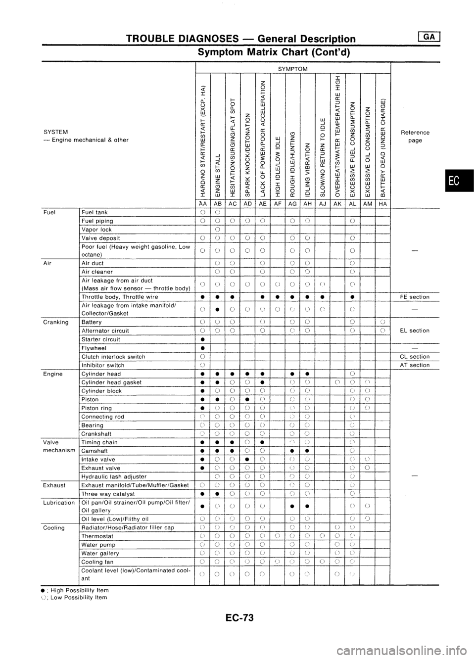
TROUBLEDIAGNOSES -General Description
Symptom MatrixChart(Cont'd)
SYMPTOM
J:
Z
CJ
~
0
I
J:
i=
LU
cL
I-
«
a:
a: ::J
UJ
0
0
LU
I-
Z
CJ
><
D..
-'
«
0
z
a:
~
LU
i=
0
z
0
a:
«
I-
0
0
LULU
D..
i=
J:
I-
«
-'
D..
:2
D..
0
0:
-'
i=
«
9
:2
::J
:2
SYSTEM
«
LL
«
0:
LU
C/J
a:
I-
0
Z
0
CJ
0
I-
Z
::J
LU
Reference
C/J
0
C/J
0
- Engine mechanical
&
other
z
0
LU
Z
I-
0
LU
I-
-'
0:
Z
Z
page
0:
(3
LU
D..
9
i=
z
Z
LU
0
0
2-
;:::
a:
0
a:
z
0
a:
I-
-'
0
0:
::J
~
LU
5:
::J
i=
::J
«
LU
-'
0
-'
J:
5:
«
-'
C/J
0
5:
0
«
I-
::J
(5
«
I-
Z
W
LU
en
LL
LU
C/J
«
00
-'
-'
a:
a:
0
I-
0
Z
D..
W
CD
I-
LU
LU
0
C/J
i=
~
LL
-'
9
:>
0
«
>
~
>-
z
0
Z
LU
(ij
C/J
a:
LU
«
~
9
J:
J:
0
Z
CJ
~
C/J
C/J
LU
I-
0:
~
CJ
Z
a:
LU LU
I-
(3
(jj
J:
a:
«
0
CJ
::J
:J
0
LU
0 0
I-
«
z
LU
D..
«
0
-'
>
><><
«
J:
LU
J:
C/J
-'
J:
a:
9
C/J
0
LU LU
CD
AA ASAC AD
AEAF
AG AH AJAK ALAM HA
Fuel Fueltank
0
U
Fuel piping
00 0
()
0 00 0
Vapor lock
U
Valve deposit
00 000 00
0
Poor fuel(Heavy weightgasoline, Low
0
C)
0 0
()
00
0
-
octane)
Air Airduct
00 0
00
0
Air cleaner
00
0
0
0
0
Air leakage fromairduct
()
(J
()
()
0
0
0 0
("
)
C'
(Mass airflow sensor -throttle body)
Throttle body,Throttle wire
••• •
••
•• •
FE
section
Air leakage fromintake manifold/
0
•
(~)
0
tJ
0
U
C;
U
-
Collector/Gasket
Cranking Battery
0
U
()
(J
00 0
':J
Alternator circuit
()
0
0
0
(J
0 0
(J
ELsection
Starter circuit
•
Flywheel
•
-
Clutch interlock switch
0
CL
section
Inhibitor switch
()
ATsection
Engine Cylinderhead
••
• •
• •
•
()
Cylinder headgasket
••
0
0
•
U
()
0
()
C'
Cylinder block
•
0
0 0
0
()
(J
0
0
Piston
••
0
•
(J
()
()
()
0
Piston ring
•
U
00
0
U
()
U
()
Connecting rod
('
0
0
00
)
U
(
)
Bearing
(i
0
()
0
()
U
0
C
Crankshaft
Cl
(~)
0 0
()
()
0
0
Valve Timingchain
•••
CJ
•
n
()
('
mechanism Camshaft
•••
0
0
•
•
0
Intake valve
•
0
0
•
0
()
':J
0
l~'
Exhaust valve
•
C)
0
()
()
U
u
()
0
HydraUlic lashadjuster
00
0
0
()
()
0
-
Exhaust Exhaust
manifoldlTube/Muffler/Gasket
C)
c:
()
()
0
U
()
U
Three waycatalyst
••
0
U
0 0
()
0
Lubrication Oil
pan/Oil strainer/Oil pump/Oilfilter/
•
Ci
0 0
0
•
•
()
0
Oil gallery
Oil level (Low)/Filthy oil
()
0
()
()()
(J
0
U
()
Cooling Radiator/Hose/Radiator
fillercap
()
0 0
()
()
C)
U
U
()
Thermostat
00
0
0
C)
0
()
00
0
Cl
Water pump
u
0
U
0
0
()
Ci
C)
U
Water gallery
U
()
0
()
0 0
U
0
U
Cooling fan
0
()
CJ
U
0
U
I)
U
()
CJ
(i
Coolant level(low)/Contaminated cool-
U
0
0 0
0
00
()
)
ant
• ;High Possibility Item
U;
Low Possibility Item
EC-73
•
Page 799 of 1701
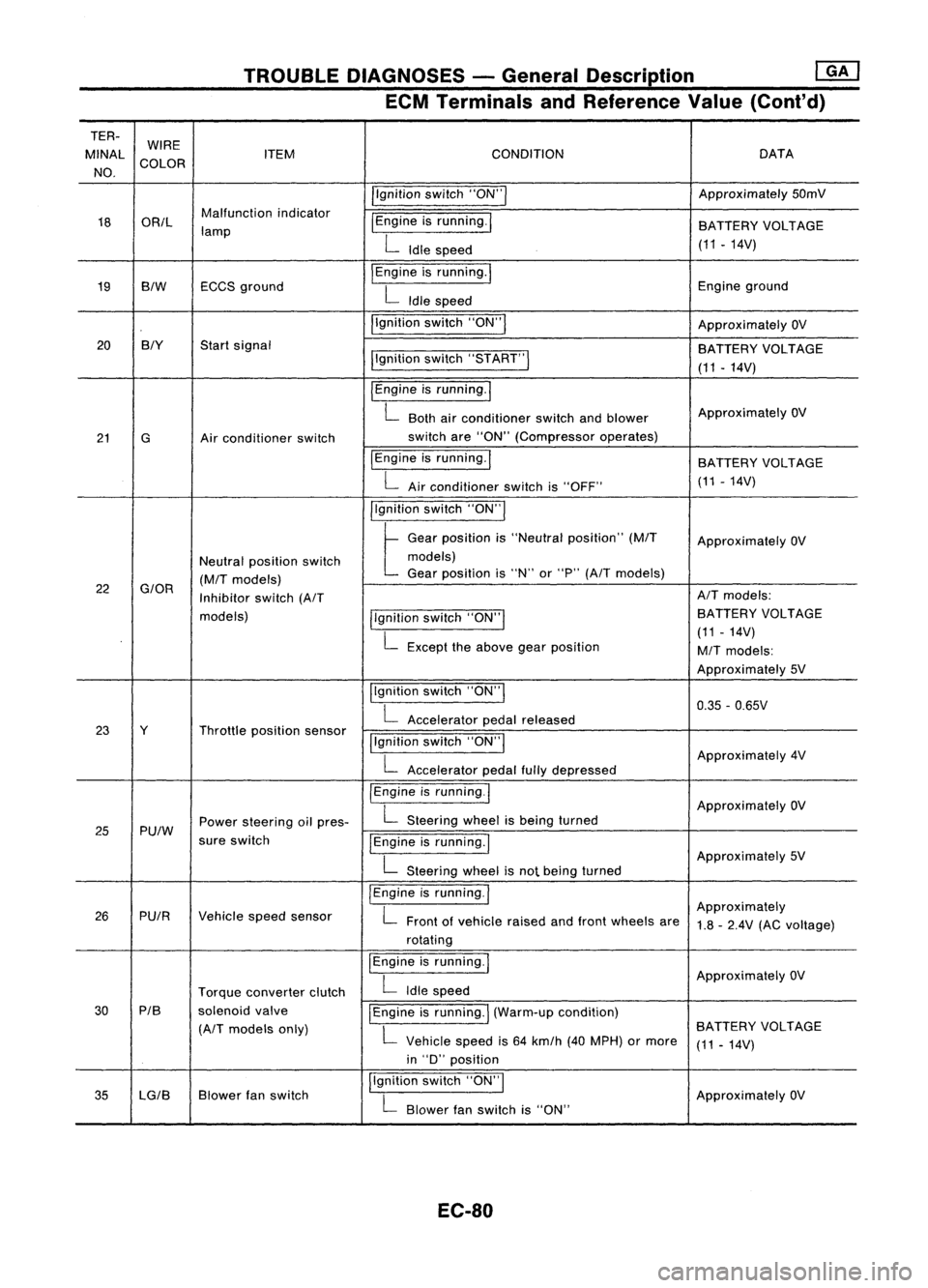
TROUBLEDIAGNOSES -General Description ~
ECM Terminals andReference Value(Cont'd)
TER- WIRE
MINAl ITEM CONDITION DATA
NO. COLOR
/'gnitionswitch"ON'" Approximately
50mV
18 OR/l Malfunction
indicator
I
Engine isrunning.
I
lamp BATTERY
VOLTAGE
L
Idle speed (11.14V)
19 BIW ECCS
ground
I
Engine isrunning.
I
Engineground
L
Idle speed
I'gnition switch"ON"
I
ApproximatelyOV
20 BIY
Startsignal
BATTERYVOLTAGE
I'gnition switch"5TART"
I
(11-14V)
I
Engine isrunning.
I
L
Both airconditioner switchandblower Approximately
OV
21 G Airconditioner switch switch
are"ON" (Compressor operates)
IEngine isrunning.
I
BATTERYVOLTAGE
L
Airconditioner switchis"OFF" (11
-14V)
I'gnition switch"ON'"
t
Ge.,
po,"'on "
"Ne"".1
po,ltlon"
(MIT
Approximately OV
Neutral position switch models)
(M/T
models) Gear
position is"N" or"P"
(A/T
models)
22
G/OR
Inhibitorswitch
(A/T AIT
models:
models) llgnitionswitch"ON'" BATTERY
VOLTAGE
L
Except theabove gearposition (11
-14V)
M/T
models:
Approximately 5V
Ilgnition switch"ON"
I
0.35-0.65V
L
Accelerator pedalreleased
23 Y Throttleposition sensor
!'gnitionswitch"ON"
I
L
Accelerator pedalfullydepressed Approximately
4V
/Engine isrunning.1
ApproximatelyOV
25 Pu/W Power
steering oilpres-
L
Steering wheelisbeing turned
sure switch
IEngineisrunning.1
L
Steering wheelisnot being turned Approximately
5V
I
Engine isrunning.
I
Approximately
26 PUIR Vehiclespeedsensor
L
Front ofvehicle raisedandfront wheels are
1.8-2.4V (ACvoltage)
rotating
I
Engine isrunning.
I
ApproximatelyOV
Torque converter clutch
L
Idle speed
30 PIB
solenoidvalve
I
Engine isrunning.
I
(Warm-up condition)
(A/T
models only)
L
Vehicle speedis64 km/h (40MPH) ormore BATTERY
VOLTAGE
(11-14V)
in "D" position
35 lG/B Blower
fanswitch I,gnition
switch"ON",
ApproximatelyOV
L
Blower fanswitch is"ON"
EC-80
Page 806 of 1701
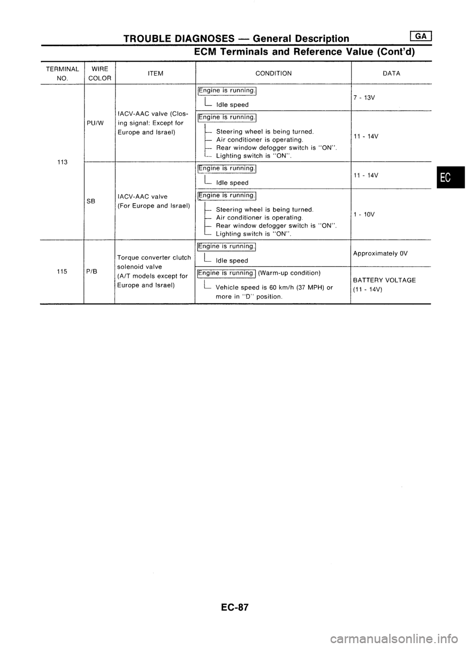
TROUBLEDIAGNOSES -General Description
[ill
ECM Terminals andReference Value(Cont'd)
TERMINAL WIRE
ITEM CONDITION
DATA
NO. COLOR
IEngineisrunning.1
7-13V
L
Idle speed
IACV-AAC valve(Clos-
~gineisrunning.1
PU/W ing
signal: Exceptfor
Europe andIsrael)
t
Stee,'", wheel',be'",t,med
11-14V
Air conditioner isoperating.
Rear window defogger switchis"ON".
Lighting switchis"ON".
113 IEngineisrunning.1
11-14V
L
Idle speed
5B IACV-AAC
valve I~ngine
isrunning.1
(For Europe andIsrael)
~Steee'", wheel"be'", t,med
Air conditioner isoperating. 1
-10V
Rear window defogger switchis"ON".
Lighting switchis"ON".
IEngine isrunning.1
ApproximatelyOV
Torque converter clutch
L
Idle speed
solenoid valve
115 P/B
(A/T
models exceptforIEngine
isrunning
I
(Warm-up condition)
L
BATTERY
VOLTAGE
Europe andIsrael)
Vehiclespeedis60 km/h (37MPH) or
(11-14V)
more in
"0"
position.
EC-87
•