Page 367 of 1701
CLUTCHRELEASE MECHANISM
SEC. 321
* :
Pay attention todirection ofbearing retainer.
m
(Q: Apply lithium-based greaseincluding molybdenum disulphide. Withdrawal
lever
(Hydraulic clutch
control)
Springpin
SCL670
•
REMOVAL ANDINSTAllATION
• Remove releasebearing bypulling bearing retainers out-
ward.
• Align spring pinwith cavity ofclutch housing andtapout
spring pin.
INSPECTION
Check thefollowing items,andreplace ifnecessary.
• Release bearing, tosee that itrolls freely andisfree from
noise, cracks, pittingorwear
• Release sleeveandwithdrawal leverrubbing surface, for
wear, rustordamage
CL-9
Page 368 of 1701
CLUTCHRELEASE MECHANISM
LUBRICATION
Lithium-based grease
including molybdenum
disulphide
ACL020•
•
Apply
recommended greasetocontact surface andrubbing
surface.
Too much lubricant mightdamage clutchdiscfacing.
CL-10
Page 369 of 1701
CLUTCHDISCANDCLUTCH COVER
~1st: 10-20(1.0-2.0,7.2-14)
2nd: 22-29 (2.2 -3.0 ,16 -22)
ACL019
SEC.
300
o
Clutchdisc
• Do not clean insolvent.
• When installing, becareful thatgrease from
main drive shaft doesnotadhere toclutch disc. Clutch
cover
m
(iJ:
Apply lithium-based greaseincluding
molybdenum disulphide.
~ :N'm (Kg-m, ft-Ib).
•
SCL221 Clutch
Disc
INSPECTION
Check thefollowing items,andreplace ifnecessary.
• Clutch disc,forburns, discoloration, oilorgrease leakage
• Clutch disc,forwear offacing
Wear limitoffacing surface torivet head:
0.3 mm (0.012 in)
• Clutch disc,forbacklash ofspline andrunout offacing.
Maximum backlashofspline (atouter edgeofdisc):
Model 180 0.7mm (0.028 in)
Model 190
and 200 0.8mm (0.031 in)
Model 215 0.9mm(0.035in)
Runout limit:
1.0 mm (0.039 in)
Distance ofrunout checkpoint(from hubcenter):
Model 180
85mm (3.35 in)
Model 190
90mm (3.54 in)
Model 200
95mm (3.74 in)
Model 215102.5mm (4.04in)
CL-11
Page 370 of 1701

CLUTCHDISCANDCLUTCH COVER
Clutch Disc(Cont'd)
INSTALLATION
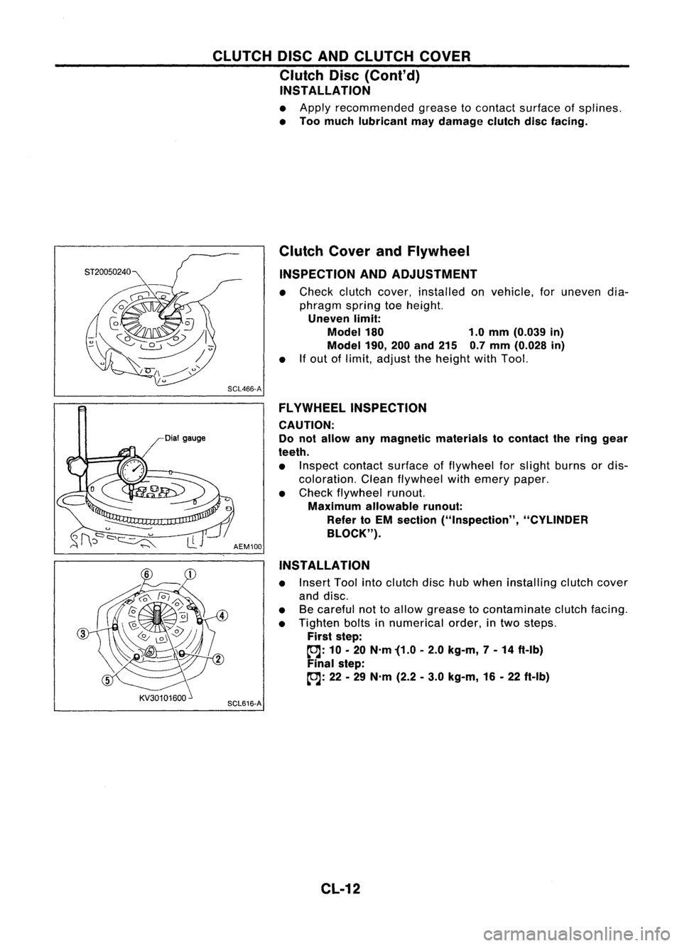
• Apply recommended greasetocontact surface ofsplines.
• Too much lubricant maydamage clutchdiscfacing.
Dial gauge Clutch
CoverandFlywheel
INSPECTION ANDADJUSTMENT
• Check clutchcover, installed onvehicle, foruneven dia-
phragm springtoeheight.
Uneven limit:
Model 180 1.0mm (0.039 in)
Model 190,
200and 215 0.7mm (0.028 in)
• Ifout oflimit, adjust theheight withTool.
SCL466-A FLYWHEEL INSPECTION
CAUTION:
Do not allow anymagnetic materials tocontact thering gear
teeth.
• Inspect contact surface offlywheel forslight burns ordis-
coloration. Cleanflywheel withemery paper.
• Check flywheel runout.
Maximum allowable runout:
Refer toEM section ("Inspection", "CYLINDER
BLOCK").
AEM100
INSTALLATION
• Insert Toolintoclutch dischubwhen installing clutchcover
and disc.
• Becareful nottoallow grease tocontaminate clutchfacing.
• Tighten boltsinnumerical order,intwo steps.
First step:
~: 10•20 N'm '(1.0 •2.0 kg-m, 7-14 ft-Ib)
Final step:
~: 22•29 N'm (2.2•3.0 kg-m, 16•22 ft-Ib)
SCL616-A
CL-12
Page 371 of 1701
SERVICEDATAANDSPECIFICATIONS (SOS)
CLUTCH CONTROL SYSTEM General
Specifications
CLUTCH MASTER CYLINDER
Engine
Type ofclutch con-
trol Except
forCD20
Mechanical CD20
Hydraulic Inner
diameter
mm(in)
15.87(5/8)
CLUTCH OPERATING CYLINDER
CLUTCH DAMPER
Inner
diameter
mm(in)
17.46
(11/16)
Inner diameter
mm(in)
19.05
(3/4)
CLUTCH DISC
Unit:mm(in)
Engine GA14DEGA15DE,
GA16DE CD20
SR20DE
Model 180190
200 215
Facing size
180x125 x3.5 190
x132 x3.5 200
x130 x3.5 215x140 x3.5
(Outer dia.xinner dia.x
(7.09x4.92 x0.138) (7.48x5.20 x0.138) (7.87
x5.12 x0.138) (8.46x5.51 x0.138)
thickness)
Thickness ofdisc assem- 7.6
-8.0 (0.299 -0.315)
bly with load 8.0
-8.4 (0.315 -0331) with3,923 N(400 kg,A2Ib) with3,923 N
(400 kg,882 Ib)
CLUTCH COVER
Engine GA14DE
GA15DE
I
GA16DE
CD20
SR20DE
Model 180 190200
215
Full-load N
(kg, Ib) 3,236(330,728) 3,432(350,772)
I
3,825
(390,860) 3,481(355,783) 4,413
(450,992)
CL-13
•
Page 372 of 1701
SERVICEDATAANDSPECIFICATIONS (SOS)
Inspection andAdjustment
CLUTCH PEDAL
Unit:mm(in)
Except forCD20 engine models
CD20engine models
Applied model
RHOLHD
RHO LHD
Pedal height "H"
159-169 (6.26 -6.65)'1 153-163 (6.02 -6.42)*2 156-166 (6.14 -6.54)'1
149-159 (5.87 -6.26)'2
Pedal freetravel "A"
11-15 (0.43 -0.59)
9-16 (0.35 -0.63)
(at pedal pad)
Withdrawal leverplay"8" 2.5-3.5 (0.098 -0.138)
-
'1: Measured fromsurface ofdash reinforcement paneltosurface ofpedal pad.
'2: Measured fromsurface ofdash lower paneltosurface ofpedal pad.
CLUTCH DISC
Unit:mm(in)
Disc model
180190
I
200
215
Wear limitoffacing surface torivet head
0.3(0.012)
Runout limitoffacing 1.0(0.039)
Distance ofrunout checkpoint(from hub
85(3.35) 90(3.54)
I
95
(3.74) 102.5(4.04)
center)
Maximum backlashofspline (atouter edgeof
0.7(0.028) 0.8(0.031)
0.9(0.035)
disc)
CLUTCH COVER
Cover model
Uneven limitofdiaphragm springtoeheight 180
1.0 (0.039)
CL-14 190
I
200
0.7 (0.028)
I
Unit:
mm(in)
215
Page 373 of 1701

ELECTRICALSYSTEM
SECTION
EL
When youread wiring diagrams:
• Read GIsection, "HOWTOREAD WIRING DIAGRAMS".
When youperform troublediagnos.es, readGIsection, "HOWTOFOllOW FLOWCHART
IN TROUBLE DIAGNOSES" and"HOW TOPERFORM EFFICIENT DIAGNOSIS FORAN
ELECTRICAL INCIDENT".
CONTENTS
PRECAUTIONS 4
Supplemental RestraintSystem(SRS)"AIR
BAG" (DualAirBag System) 4
Supplemental RestraintSystem(SRS)"AIR
BAG" (Single AirBag System) 4
HARNESS CONNECTOR 5
Description 5
STANDARDIZED RELAy 6
Description 6
POWER SUPPLY ROUTING 8
Schematic 8
Wiring Diagram -POWER - 10
Fuse 19
Fusible Link 19
Circuit Breaker 19
GROUND DISTRIBUTION 20
BATTERy 25
How toHandle Battery 25
Battery TestandCharging Chart.. 28
Service DataandSpecifications (SOS) 32
STARTING SySTEM
33
Wiring Diagram -START - 33
Trouble Diagnoses 35
Construction 36
Removal andInstallation .45
Magnetic SwitchCheck .46
Pinion/Clutch Check 46
Brush Check 46
Yoke Check 47
Armature Check 48
Assembly .49
Service DataandSpecifications (SDS) 50
CHARGING SYSTEM 52
Wiring Diagram -CHARGE - 52
Trouble Diagnoses 54Construction
55
Removal andInstallation 57
Disassembly 57
Rotor Check 57
Brush Check 58
Stator Check 58
Diode Check 59
Assembly 60
Service DataandSpecifications (SDS) 61
COMBINATION SWITCH 62
Combination Switch/Check 62
Replacement 64
HEADLAMP -Without Daytime lightSystem -65
Wiring Diagram -H/LAMP - 65
Trouble Diagnoses 67
HEADLAMP -Daytime lightSystem - 68
Operation (Daytimelightsystem) 68
System Description 69
Schematic 70
Wiring Diagram -DTRL - 71
Trouble Diagnoses (DaytimeLight) 74
HEADLAMP 75
Bulb Replacement... 75•
Aiming Adjustment. 75
HEADLAMP -Headlamp Aiming
Control- 77
Wiring Diagram -AIM - 77
Description 81
EXTERIOR LAMP 82
Clearance, LicenseandTail Lamps/Schematic 82
Clearance, LicenseandTail Lamps/Wiring
Diagram -TAILIL - 83
Stop Lamp/Wiring Diagram-STOP/L - 92
Back-up Lamp/Wiring Diagram-BACK/L -94
Front FogLamp/Wiring Diagram-F/FOG -96
Front FogLamp BulbReplacement 101
Page 407 of 1701

STARTINGSYSTEM
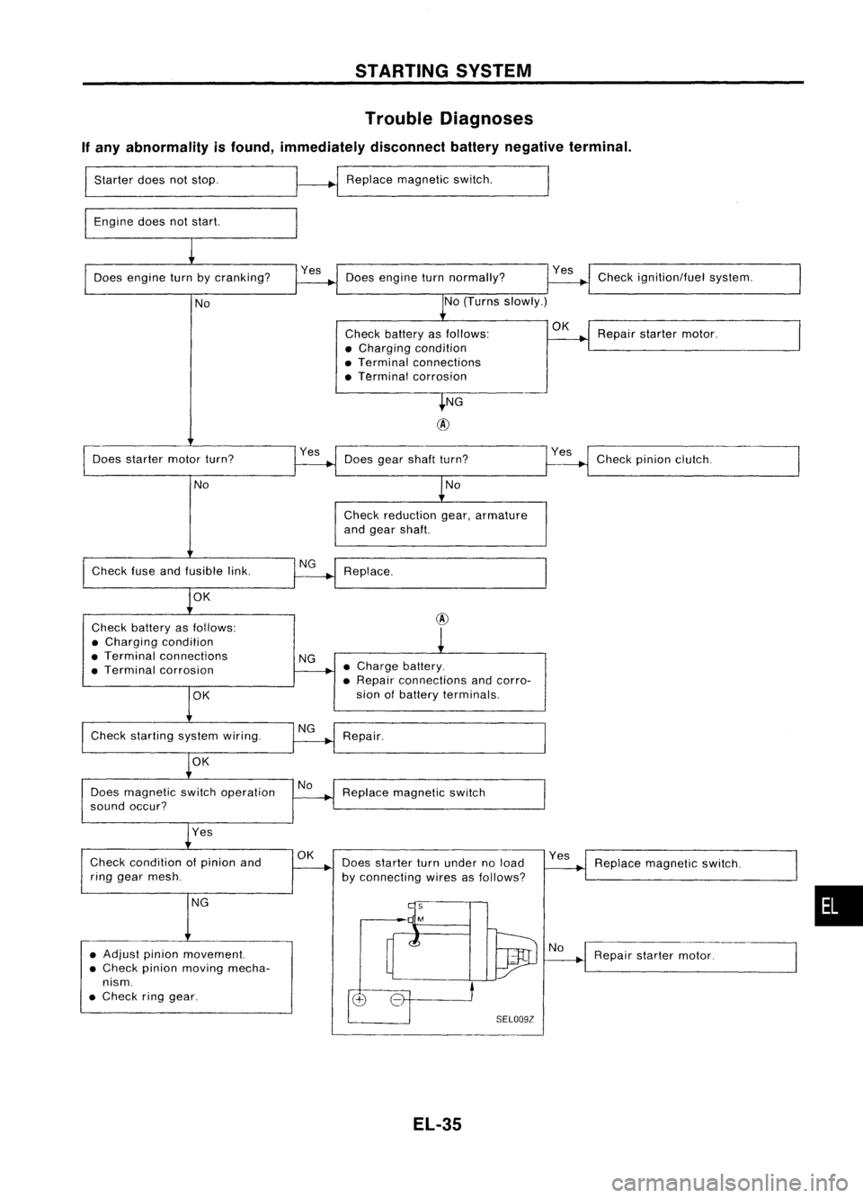
Trouble Diagnoses
If any abnormality isfound, immediately disconnectbatterynegative terminal.
Starter doesnotstop.
Engine doesnotstart. Replace
magnetic switch.
Does engine turnbycranking? Doesengine turnnormally? Check
ignition/fuel system.
No No
(Turns slowly.)
Check battery asfollows:
OK
Repairstarter motor.
• Charging condition
• Terminal connections
• Terminal corrosion
NG
@
Does starter motorturn? Yes
Doesgearshaft turn? Checkpinionclutch.
No No
Check reduction gear,armature
and gear shaft.
Check fuseandfusible link. Replace.
OK
Check battery asfollows:
@
• Charging condition
• Terminal connections
NG
• Terminal corrosion •
Charge battery.
• Repair connections andcorro-
OK
sian
ofbattery terminals.
Check starting systemwiring.
Repair.
OK
Does magnetic switchoperation No
Replace magnetic switch
sound occur?
Yes
Check condition ofpinion and
OK
Doesstarter turnunder noload Yes
Replace magnetic switch.
ring gear mesh.
byconnecting wiresasfollows?
NG
•
• Adjust pinionmovement.
Repairstarter motor.
• Check pinionmoving mecha-
nism .
• Check ringgear.
SELOO9Z
EL-35