Page 1416 of 1701
TROUBLEDIAGNOSES
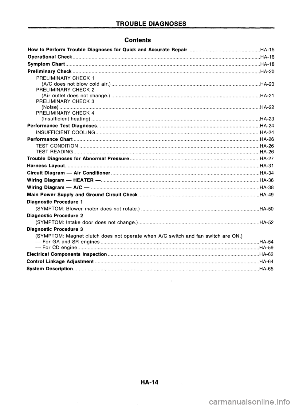
Contents
How toPerform TroubleDiagnoses forQuick andAccurate Repair HA-15
Operational Check HA-16
Symptom Chart HA-18
Preliminary Check HA-20
PRELIMINARY CHECK1
(A/C
does notblow coldair.) HA-20
PRELIMINARY CHECK2
(Air outlet doesnotchange.) HA-21
PRELIMINARY CHECK3
(Noise) HA-22
PRELIMINARY CHECK4
(I nsufficient heating) HA-23
Performance TestDiagnoses HA-24
INSUFFICIENT COOLING HA-24
Performance Chart HA-26
TEST CONDITION HA-26
TEST READING HA-26
Trouble Diagnoses forAbnormal Pressure HA-27
Harness Layout. HA-31
Circuit Diagram -Air Conditioner HA-34
Wiring Diagram -HEATER - HA-36
Wiring Diagram -AIC - HA-38
Main Power Supply andGround CircuitCheck HA-49
Diagnostic Procedure1
(SYMPTOM: Blowermotordoesnotrotate.) HA-50
Diagnostic Procedure2
(SYMPTOM: Intake doordoes notchange.) HA-52
Diagnostic Procedure3
(SYMPTOM: Magnetclutchdoesnotoperate when
A/C
switch andfanswitch areON.)
- For GAand SRengines HA-54
- For CDengine HA-59
Electrical Components Inspection HA-62
Control Linkage Adjustment HA-64
System Description HA-65
HA-14
Page 1420 of 1701
TROUBLEDIAGNOSES
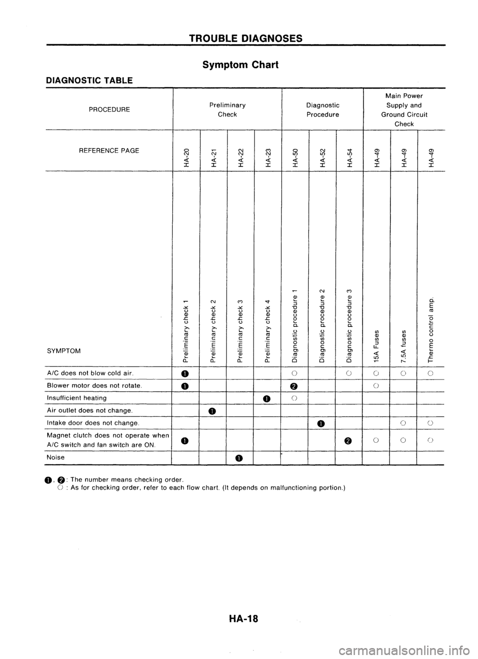
Symptom Chart
DIAGNOSTIC TABLE
MainPower
PROCEDURE Preliminary
DiagnosticSupplyand
Check ProcedureGroundCircuit
Check
REFERENCE PAGE
0
N
N
C')
0 N
"'"
O'J
O'JO'J
N NN
LO LO
LO
"'""'""'"
.d: .d:.d: .d:.d:
I
.d: .d:.d:
.d:
~
:c :c:c :c
:c :c:c :c:c:c
~
N
C')
Q) Q)Q)
ci.
~
N
C')
"'" ....
....
....
:J :J:J
E
-'" -'"-'" -'"
"0
"0"0
u uu u
Q)Q) Q)
«l
Q) Q)Q) Q)
uuu
e
.c
.c.c .c
000
u uu u
....
........
>.
~
>.
>.
0.
0.0.
C
~
....
....
uu u
UJ UJ
0
«l «l
«l
~ ~~
OJ
Q)
u
c cc
c
UJUJ
0
.-
.-
.-
000
:J
.2
E E
E E
ccc
u..
E
SYMPTOM
.-
-
.
-
OJOJOJ
~
....
~
OJ
Qj
Qj
«l«l
«l
~ Q)
.... .... ....
Ci Ci Ci
LO
LO
.c
a.. a..a..
a..
~
r--
f-
AIC
does notblow coldair.
0
0
0
0
00
Blower motordoesnotrotate.
0
fj
()
Insufficient heating
0
()
Air outlet doesnotchange.
0
Intake doordoes notchange.
0
0
0
Magnet clutchdoesnotoperate when
0
fj
0
0
0
AIC
switch andfanswitch areON.
Noise
0
0,
fj:
The number meanschecking order.
C :
As for checking order,refertoeach flowchart. (Itdepends onmalfunctioning portion.)
HA-18
Page 1424 of 1701
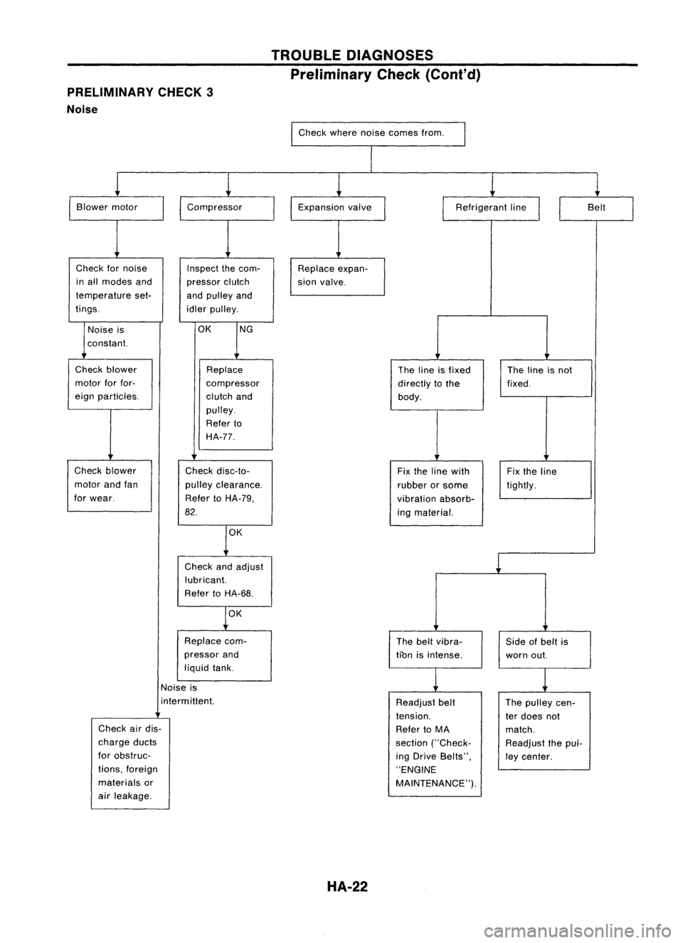
PRELIMINARY CHECK3
Noise TROUBLE
DIAGNOSES
Preliminary Check(Coni'd)
Check wherenoisecomes from.
I
I
Blower motor
Check fornoise
in all modes and
temperature set-
tings.
I
Compressor
Inspect thecom-
pressor clutch
and pulley and
idler pulley. Expansion
valve
Replace expan-
sion valve.
I
Refrigerant line
II
Belt
I
Noise is
constant.
OK
NG
Check blower
motor forfor-
eign particles.
Check blower
motor andfan
for wear. Replace
compressor
clutch and
pulley.
Refer to
HA-77.
Check disc-to-
pulley clearance.
Refer toHA-79,
82.
OK
Check andadjust
lubricant.
Refer toHA-68.
OK
Replace com-
pressor and
liquid tank. The
lineisfixed
directly tothe
body.
Fix the line with
rubber orsome
vibration absorb-
ing material.
The beltvibra-
tion isintense. The
lineisnot
fixed.
Fix the line
tightly.
Side ofbelt is
worn out.
Noise is
i nterm ittent.
Check airdis-
charge ducts
for obstruc-
tions, foreign
materials or
air leakage.
HA-22
Readjust
belt
tension.
Refer toMA
section ("Check-
ing Drive Belts",
"ENGINE
MAINTENANCE"). The
pulley cen-
ter does not
match.
Readjust thepul-
ley center.
Page 1427 of 1701
TROUBLEDIAGNOSES
Performance TestDiagnoses (Cont'd)
@
Malfunctioning blowermotorfan
Loose fan!lmproper contactoffan
and case!Deformed fan Malfunctioning
electricalcircuit
Discontinued wiringorcomponent
circuits orpoor connection!
Malfunctioning resistor,amplifier,
etc.! Burned outfuse orlow bat-
tery voltage Malfunctioning
blowermotor
internal circuit
Magnet clutchdoesnotengage.
CHECK MAGNET CLUTCH
(coil circuit, disc-to-pulley clear-
ance). Magnet
clutchslipping
Beltslipping
CHECK COMPRESSOR BELTAND
BELT TENSION.
CHECK ELECTRICAL CIRCUIT
(wiring, components circuit).
CHECK ACTIVATION OFSAFETY!
PROTECTION DEVICES(suchas
pressure switch,etc.). Malfunctioning
internalpartsof
clutch, compressor
Foreign particles onclutch fric-
tional surface orexcessive disc
clearance
Malfunctioning electricalcircuit
(poor connection, lowbattery
voltage, etc.)
HA-25
•
Page 1456 of 1701
TROUBLEDIAGNOSES
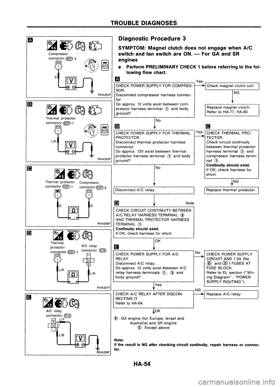
Diagnostic Procedure3
SYMPTOM: Magnetclutchdoesnotengage when
Ale
switch andfanswitch areON. -For GAand SR
engines
• Perform PRELIMINARY CHECK1before referring tothe fol-
lowing flowchart.
Replacemagnetclutch.
Refer toHA-77, HA-80.
Check
magnet clutchcoil.
NG
Yes
m
CHECK POWER SUPPLY FORCOMPRES-
SOR. Disconnect compressor harnessconnec-
tor. Do approx. 12volts existbetween com-
pressor harness terminal
ill
and body
ground?
RHA354F
s
Compressor
connector
@QD-2
~
RHA357FRHA356F
NG
CHECK POWER SUPPLY
CIRCUIT AND7.5A(No.
[Q]
and ~)FUSES AT
FUSE BLOCK.
Refer toEL section ("Wir-
ing Diagram", "POWER
SUPPLY ROUTING").
Replace AICrelay.
I
Replace thermalprotector.
[;J
Yes CHECK THERMAL PRO-
TECTOR.
Check circuit continuity
between thermalprotector
harness terminal
ill
and
compressor harnesstermi-
nal
ill.
Continuity shouldexist.
If OK, check harness for
shorl.
No
NG
CHECK
CIRCUIT CONTINUITY BETWEEN
AIC RELAY HARNESS TERMINAL @
AND THERMAL PROTECTOR HARNESS
TERMINAL
ill.
Continuity shouldexist.
If OK, check harness forshorl. Note
Yes
CHECK
POWER SUPPLY FORAIC
RELAY.
Disconnect AICrelay.
Do approx. 12volts exist!)etween AIC
relay harness terminals
ill,
@
and
body ground?
CHECK AICRELAY AFTER DISCON-
NECTING IT.
Refer toHA-64.
Disconnect
AICrelay. NoNo
[;)
CHECK POWER SUPPLY FORTHERMAL
PROTECTOR.
Disconnect thermalprotector harness
connector. Do approx. 12Vexist between thermal
protector harnessterminal
ill
and body
ground?
OK
@:
GAengine (forEurope, Israeland
Australia) andSRengine
@:
Except above
RHA355F
~ i5@a
Thermal protector
AIC
relay
connector
@-1
connector
(ill)
,"R~~t
[1[]
lIR
lIR
Thermal
protector
connector
@QD-1
~
Thermal protector Compressor
connector
@QD-1
connector
@QD-2
~ ~
~ ~ ls
~
~15~
AlC relay
connector
(ill)
~lIY
RHA358FNote:
If the result isNG after checking circuitcontinuity, repairharness orconnec-
tor.
HA-54
Page 1461 of 1701
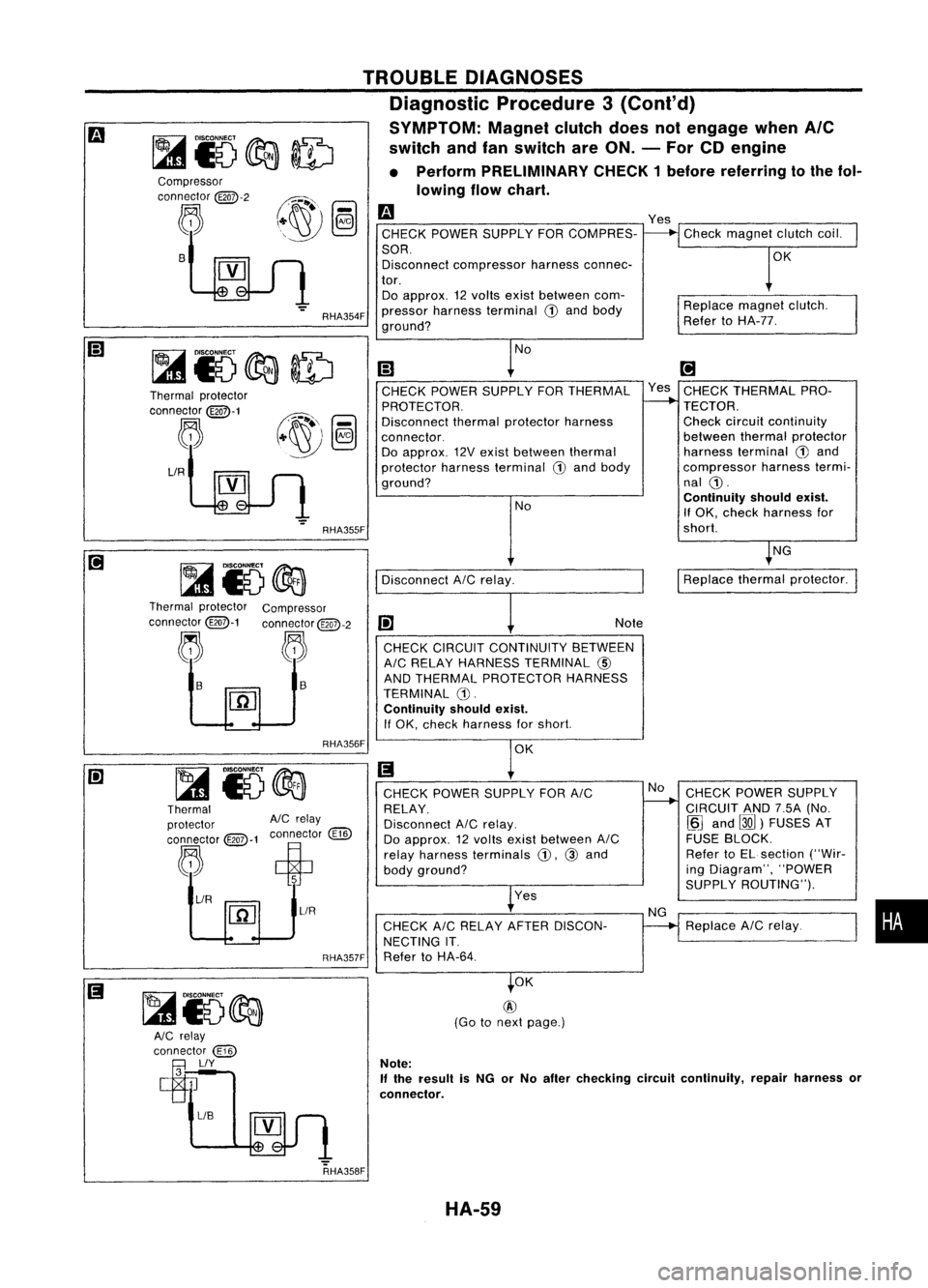
TROUBLEDIAGNOSES
Diagnostic Procedure3(Cont'd)
SYMPTOM: Magnetclutchdoesnotengage whenAle
switch andfanswitch areON. -For CDengine
• Perform PRELIMINARY CHECK1before referring tothe fol-
lowing flowchart.
Compressor
connector
@Q7>-2
~ B
Thermal protector
connector
@Q7>-1
~
LlR
RHA354F
RHA355F
m
CHECK POWER SUPPLY FORCOMPRES-
SOR. Disconnect compressor harnessconnec-
tor. Do approx. 12volts exist between com-
pressor harness terminal
CD
and body
ground?
No
(;J
CHECK POWER SUPPLY FORTHERMAL
PROTECTOR.
Disconnect thermalprotector harness
connector. Do approx. 12Vexist between thermal
protector harnessterminal
G)
and body
ground?
NoYes
Check magnet clutchcoil.
OK
Replace magnetclutch.
Refer toHA-77.
[!]
Yes CHECK THERMAL PRO-
TECTOR. Check circuitcontinuity
between thermalprotector
harness terminal
G)
and
compressor harnesstermi-
nal
CD.
Continuity shouldexist.
If OK. check harness for
short.
NG
Disconnect AICrelay.
I
Replace thermalprotector.
Thermal protector Compressor
connector@-1 connector@QD-2
j. ~~
1-
I1iJ
RHA356F Note
CHECK CIRCUIT CONTINUITY BETWEEN
AIC RELAY HARNESS TERMINAL
@)
AND THERMAL PROTECTOR HARNESS
TERMINAL G).
Continuity shouldexist.
If OK. check harness forshort.
OK
Thermal
protector AlCrelay
connector @:>-1connector
@])
~ ciP
~/R ~
1
~L1R
RHA357FCHECK
POWER SUPPLY FORAIC
RELAY.
Disconnect AICrelay.
Do approx. 12volts exist between AIC
relay harness terminals
CD.
@and
body ground?
Yes
CHECK AICRELAY AFTERDISCON-
NECTING IT.
Refer toHA-64. No
NG CHECK
POWER SUPPLY
CIRCUIT AND7.5A(No.
~J
and
00)
FUSES AT
FUSE BLOCK.
Refer toEL section ("Wir-
ing Diagram", "POWER
SUPPLY ROUTING").
Replace AICrelay.
•
RHA358F OK
@
(Go tonext page.)
Note:
If
the result isNG orNo after checking circuitcontinuity, repairharness or
connector.
HA-59
Page 1479 of 1701
SERVICEPROCEDURES
Compressor -Model DKV-11D andDKV-14D
(ZEXEL make)
SHA927DB
SEC.
274
Clutchdisc ~4
-6
(0.4 -0.6, 35•52)
Thermalprotector
~ 15-18 (1.5 -1.8, 11•13)
~ :N'm (kg-m, in-Ib)
~ :N'm (kg-m, ft-Ib)
Drive plate
Shim SHA098EA Compressor
Clutch
REMOVAL
• When removing centerbolt,holdclutch discwithclutch disc
wrench.
• Remove thedrive plateusing ToolKV99232340.
Insert holder's threepinsintothedrive plate. Rotate the
holder clockwise tohook itonto theplate. Then, tighten the
center bolttoremove thedrive plate.
When tightening thecenter bolt,insert around bar
(screwdriver, etc.)between twoofthe pins (asshown inthe
left-hand figure)toprevent driveplaterotation. Afterremov-
ing the drive plate, remove theshims fromeither thedrive
shaft orthe drive plate.
HA-77
•
Page 1480 of 1701

•Pulley removal
Use anycommercially availablepulleypuller. Position the
center ofiton the end ofthe drive shaft, andremove the
pulley assembly.
For pressed pulleys
To prevent deformation ofthe pulley groove, thepuller
claws should behooked into(not under) thepulley groove.
For machine latchedpulleys
Align thepulley pullergroove withthepulley groove, and
then remove thepulley assembly.
• Remove thefield coilharness clipusing ascrewdriver.
• Remove thethree fieldcoilfixing screws andremove the
field coil.
SERVICE
PROCEDURES
Compressor Clutch(Cont'd)
• Remove thesnap ringusing external snapringpliers.
RHA072C
SHA099EA
External
snap
ring pliers
ulley puller
~/S"'wd""'"
g-
Fieldcoil
Snap
ring
KV99233130
RHA074C
Shim
J
Snap ring
BOll\
1
JJ _
~crew
~
~
L
Clutch disc
RHA075CINSPECTION
Clutch disc:Ifthe contact surface showssignsofdamage due
to excessive heat,replace clutchdiscandpulley.
Pulley: Checktheappearance ofthe pulley assembly. Check
the contact surface ofthe pulley forany sign ofexcessive groov-
ing due toslippage. Ifany sign isfound, replace boththepul-
ley and clutch disc.!hecontact surfaces ofthe pulley assem-
bly should becleaned withasuitable solventbeforereinstalla-
tion.
Coil: Check coilforloose connection orcracked insulation.
INSTAllATION
• Install thefield coil.
Be sure toalign thecoil's pinwith thehole inthe compressor's
front head.
• Install thefield coilharness clipusing ascrewdriver.
RHA076C HA-78