Page 359 of 1701
CLUTCH
SECTION
CL
CONTENTS
PRECAUTIONS ANDPREPARATION 2
Precautions 2
Preparation 2
CLUTCH SYSTEM-Hydraulic Type
3
CLUTCH SYSTEM-Mechanical Type 4
INSPECTION ANDADJUSTMENT
5
Adjusting ClutchPedal 5
Bleeding Procedure -Hydraulic type 5
HYDRAULIC CLUTCHCONTROL.. 6
Clutch Master Cylinder 6Operating
Cylinder 7
Clutch Damper 8
CLUTCH RELEASE MECHANiSM 9
CLUTCH DISCANDCLUTCH COVER 11
Clutch Disc 11
Clutch CoverandFlywheel 12
SERVICE DATAANDSPECIFICATIONS (SDS)13
General Specifications 13
Inspection andAdjustment 14
•
Page 360 of 1701

PRECAUTIONSANDPREPARATION
Precautions
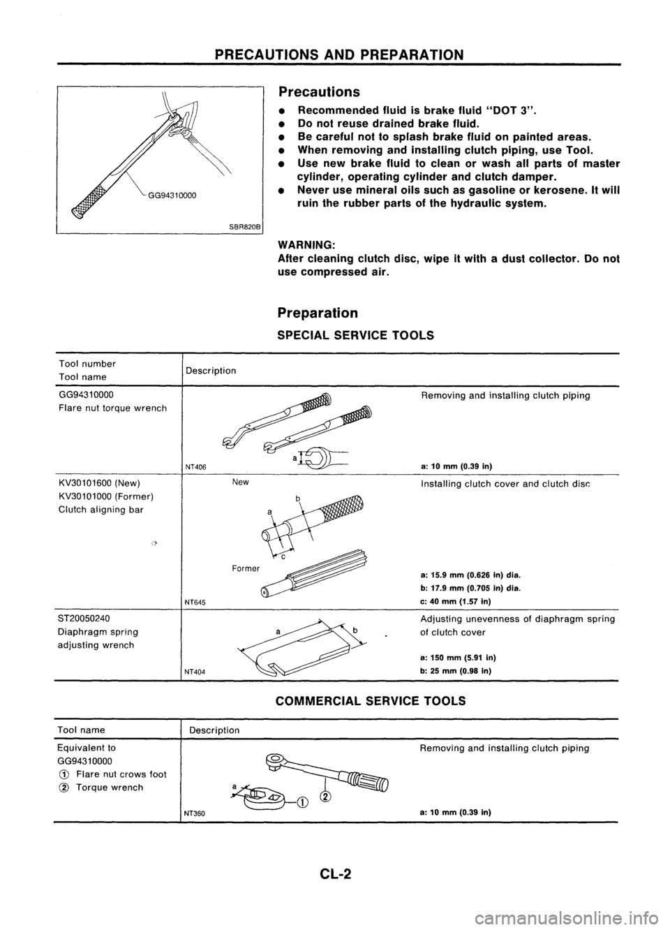
• Recommended fluidisbrake fluid"DOT 3".
• Donot reuse drained brakefluid.
• Becareful nottosplash brakefluidonpainted areas.
• When removing andinstalling clutchpiping, useTool.
• Use new brake fluidtoclean orwash allparts ofmaster
cylinder, operating cylinderandclutch damper.
• Never usemineral oilssuch asgasoline orkerosene. Itwill
ruin therubber partsofthe hydraulic system.
Tool number
Tool name
SBR820B
WARNING:
After cleaning clutchdisc,wipe itwith adust collector. Donot
use compressed air.
Preparation
SPECIAL SERVICE TOOLS
Description
New
GG94310000
Flare nuttorque wrench
KV30101600 (New)
KV30101000 (Former)
Clutch aligning bar
ST20050240 Diaphragm spring
adjusting wrench
NT406
NT645
NT404
Removing
andinstalling clutchpiping
a:
10
mm
(0.39
in)
Installing clutchcoverandclutch disc:
a:
15.9
mm
(0.626 In)dia.
b: 17.9 mm(0.705 in)dia.
c: 40 mm (1.57 in)
Adjusting unevenness ofdiaphragm spring
of clutch cover
a: 150 mm (5.91 in)
b: 25
mm
(0.98
in)
Tool name
Description
COMMERCIAL
SERVICETOOLS
Equivalent to
GG9431 0000
CD
Flare nutcrows foot
@
Torque wrench
NT360
Removing
andinstalling clutchpiping
a: 10 mm (0.39 in)
CL-2
Page 361 of 1701
SCL667
CLUTCH
SYSTEM -Hydraulic Type
m
(bl:
Apply lithium-based greaseincluding
molybdenum disulphide.
~ :N.m (kg-m. ft-Ib)
~ :N.m (kg-m. in-Ib)
•
G)
Clutch pedalbracket
@
Clutch master cylinder
@
Assist spring
@
Bushing
@
Pin
@
Stopper rubber
(J)
Operating cylinder
@
Airbleeder screw
@
Withdrawal lever
@J
Release bearing
@
Clutch hose
@
Operating cylindersupport
bracket
@
Clutch lever
@
Spring pin
@ Operating cylinderbracket
CL-3 @
Clutch cover
@
Clutch disc
@
Clutch pedal
@
Clevis pin
@
Pedal stopper
@
Fulcrum pin
Page 362 of 1701

CLUTCHSYSTEM-Mechanical Type
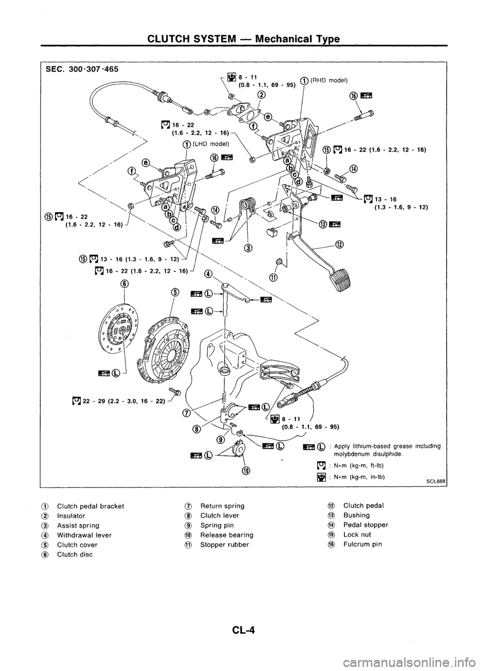
SEC. 300'307.465
SCL668
\~
8-11
(RHO model)
(0.8 -1.1, 69-95)
r""
@
@m
~~~ ~
/~
to.J 16-22
f
77'\
-j, ~'
, (1.6.2.2,12-16)~ ~
M-
.
(LHD model)
Of~ ':,
,/ I
r';, ~~
I'
@
to.J 16•22 (1.6 -2.2, 12•16)
/ fA'l
@m~
a!',~~
I
,/' ~~ {l
,-0 ~
be\.\~':~ @
<
01Q'?0'J:l'e..------ ,
d~~
~;, 1
v,~
~, ~i,:
1r
J
~m
to.J13-16
c
I~..--.......
~JO
a,
',@/ :'~' ~ (1.3•1.6, 9-12)
@
to.J 16-22 ~
be c
_1
L~---- .~
.Jl
(1.6 -2.2, 12-16)
'~d' ~
C1J.~,
@m
'm (
@ ,
@
to.J 13-16 (1.3 •1.6, 9•12) .~. ~
I
to.J 16-22 (1.6 -2.2, 12-16)
@~ ~
@ ~~@
m(Q .
-m~.
m(Q ~
~h
<:
(7\I~ ~ .~
\ ~J;i::::;~
l"J" -
29 (2.2 -3.0,
1.-
22)1>
0~~
'I
~ ¥:11)
@-..........t>'"l(0.8-1.1,69-95)
/l~~
~ ~I!C!
I!C!
ApplV Ilth'"m-",,' om,,,
'001""00
m
(Q
molybdenumdisulphide.
Iiii\ .
[OJ;
N.m (kg-m, ft-lb)
~
IjJ;N'm (kg-m, in-Ib)
G)
Clutch pedalbracket
(1)
Return
spring @
Clutch pedal
@
Insulator
@
Clutch lever
@
Bushing
@
Assist spring
@
Spring pin
@
Pedal stopper
@
Withdrawal lever
@J
Release
bearing
@
Lock nut
@
Clutch cover
@
Stopper rubber
@
Fulcrum pin
@
Clutch disc
CL-4
Page 363 of 1701

INSPECTIONANDADJUSTMENT
Pedal stopper
Dash lower
panel (except
CD20 engine //
model)
/L
Floor car-pet
L
Dash reinforcement panel
(CD20 engine model)
Adjusting
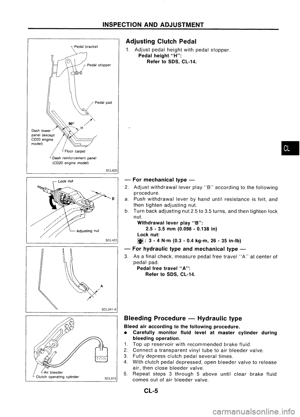
ClutchPedal
1. Adjust pedalheight withpedal stopper.
Pedal height
"H":
Refer to
50S,
CL-14.
•
SCL625
SCL423 -
For mechanical type-
2. Adjust withdrawal leverplay"8"according tothe following
procedure_
a. Push withdrawal leverbyhand untilresistance isfelt, and
then tighten adjusting nut.
b. Turn backadjusting nut2.5to3.5 turns, andthen tighten lock
nut.
Withdrawal leverplay
"B":
2.5 -3.5 mm (0.098 -0.138 in)
lock nut:
~: 3-
4 N'm (0.3-0.4 kg-m, 26-35 in-Ib)
- For hydraulic typeandmechanical type-
3. Asafinal check, measure pedalfreetravel "A"atcenter of
pedal pad.
Pedal freetravel
"A":
Refer to
50S,
CL-14.
B
Bleeding Procedure -Hydraulic type
Bleed airaccording tothe following procedure.
• Carefully monitorfluidlevel atmaster cylinder during
bleeding operation.
1. Top upreservoir withrecommended brakefluid.
2. Connect atransparent vinyltubetoair bleeder valve.
3. Fully depress clutchpedalseveral times.
4. With clutch pedaldepressed, openbleeder valvetorelease
air, then close bleeder valve.
5. Repeat steps3through 5above untilclear brake fluid
SCL613
comesoutofair bleeder valve.
SCL341-A
Adjusting
nut
Lock
nut
CL-5
Page 364 of 1701

HYDRAULICCLUTCHCONTROL
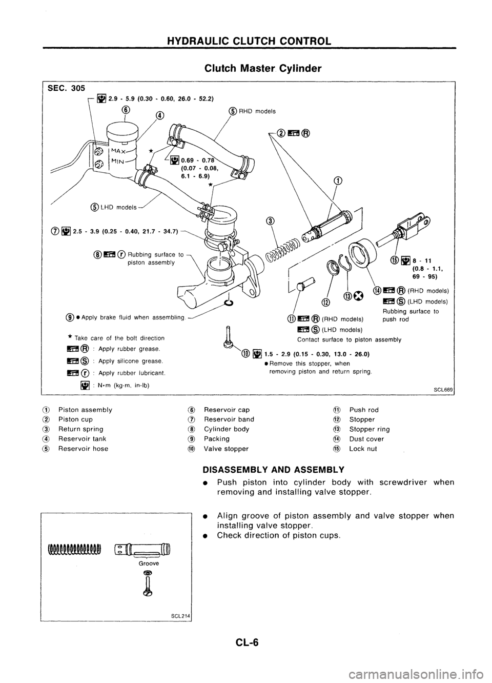
Clutch Master Cylinder
SEC. 305
SCL669
~
2.9 •5.9 (0.30 •0.60, 26.0•52.2)
@
@
m
CD
Rubbing surfaceto
piston assembly
@LHD
models
m @:Apply silicone grease,
m
CD:
Apply rubber lubricant.
Iil :
N.m (kg-m. in-Ib)
CD
/
(1), ~
1'.
~'. ~". @liJa-
11
( ~I'
(08.'.1,
,<
I
~f
/@O@I1I!@(A':o'::"'1
~ @
m@(LHDmodels)
Rubbing surfaceto
@.
Apply brakefluidwhen assembling.
(jJ)
m @(RHD models) pushrod
~ m@(LHD models)
*
Take careofthe bolt direction Contactsurfacetopiston assembly
m@ :Apply rubber grease.
@~
1.5-2.9 (0.15 -0.30, 13.0-26.0)
• Remove thisstopper, when
removing pistonandreturn spring.
(j)
~
2.5 -3.9 (0.25 -0.40, 21.7-34.7)
(1)
Piston assembly
@
Reservoir
cap
@
Piston cup
(])
Reservoir
band
@
Return spring
@
Cylinder body
@
Reservoir
tank
@
Packing
@
Reservoir hose
@)
Valve stopper
@
Push rod
@
Stopper
@
Stopper ring
@
Dustcover
@
Lock nut
DISASSEMBLY ANDASSEMBLY
• Push piston intocylinder bodywithscrewdriver when
removing andinstalling valvestopper.
• Align groove ofpiston assembly andvalve stopper when
installing valvestopper.
• Check direction ofpiston cups.
c;D.=:
=.J3@
Groove
SCL214 CL-6
Page 365 of 1701
HYDRAULICCLUTCHCONTROL
Clutch Master Cylinder (Cont'd)
INSPECTION
Check thefollowing items,andreplace ifnecessary.
• Rubbing surfaceofcylinder andpiston, foruneven wear,
rust ordamage
• Piston withpiston cup,forwear ordamage
• Return spring, forwear ordamage
• Dust cover, forcracks, deformation ordamage
• Reservoir, fordeformation ordamage
Operating Cylinder
SEC. 306
Operatingcylinder
m
@
•
/
Piston spring ,
/ I
Piston cup
m~;}
Alwaysreplace afterevery disassembly asaset.
~d /
/Piston
~ti)
d
~ Q
~,""d
(il@
Dust cover /
J
7:\
I
{
'c
Bleeder screw
IiIS.9 -9.8 N.m .
(0.6 -1.0 kg-m, 52.2-86.7 In-Ib)
m
lR):
Apply rubber grease.
SCL607-B
INSPECTION
Check thefollowing items,andreplace ifnecessary.
• Rubbing surfaceofcylinder andpiston, foruneven wear,
rust ordamage
• Piston withpiston cup,forwear ordamage
• Piston spring, forwear ordamage
• Dust cover, forcracks, deformation ordamage
CL-7
Page 366 of 1701
HYDRAULICCLUTCHCONTROL
Clutch Damper
SEC. 306
Bleeder screw
1i15.9 -9.8
(0.60 -1.00, 52.2.86.7)
m
@Rubbing surfaceto
piston assembly
Piston cup
m
@
J'
Piston assembly
m
@
Contact surfacetopiston assembly
Damper rubber~
m
@:Apply rubber grease.
II] :N'm (kg-m. in-Ib) Cylinder
body
(LHD model)
11]5.1
-6.5
(0.52 -0.66,
45.1 -57.5)
- Damper cover
(RHD model)
II]
2.9 -5.9
(0.30 -0.60,
25.7 -52.2)
SCL672
INSPECTION
• Check cylinder andpiston rubbing surfaceforuneven wear,
rust ordamage. Replaceifnecessary.
• Check damper rubberandpiston cupforcracks, deforma-
tion ordamage. Replaceifnecessary.
CL-8