Page 169 of 255
10Remove the securing screws and detach
the C and D-pillar trim panels.
11Remove the top of the facia panel.
12Remove the securing screw from the base
of the A-pillar trim on each side. Detach the A-
pillar trim panels.
13Remove the headlining through the
tailgate, peeling it back from around the sliding
roof (when applicable - see paragraph 15).
14Refitting is essentially a reversal of the
removal procedure. The services of an
assistant will be required during the initial
stages of refitting.
15When a sliding roof is fitted, the headlining
is secured around the aperture with double-
sided adhesive tape.
1To remove a manually-adjusted mirror, first
pull off the operating lever cover. Remove the
triangular trim panel which covers the mirror
mounting: this panel is secured by a single
screw concealed under a cover. Pull out thecontrol retaining clip (see illustrations).
2For electrically-adjusted mirrors, remove the
door interior trim panel (including the triangular
trim panel) and peel back the top part of the
foam sheet for access to the mirror multi-plug.
Disconnect the multi-plug.
3For all mirrors, support the mirror and
remove the three securing screws. Lift the
mirror off the door, disengaging the base from
the rubber seal (see illustration).
4Refit by reversing the removal operations.
1Remove the mirror from the windscreen by
“sawing” through the adhesive bond with a
piece of nylon cord.
2Clean the mirror base and the mounting
area on the windscreen with methylated spirit.
Both items must be perfectly clean, and the
windscreen must be at room temperature
(20°C/68°F approx).
3Peel off the backing paper from one side of
the special adhesive patch. Press the stickyside of the patch firmly onto the mirror base.
4Warm the mirror base and patch to 50°
to 70°C (122°to 158°F). Immediately remove
the backing paper from the other side of the
patch and press the mirror firmly onto the
mounting area. Hold it in position for at least
two minutes, and do not attempt to adjust the
mirror for at least half an hour.
5Beware of using proprietary adhesives to
attach the mirror to the windscreen: not all are
suitable and some may leave residues which
are difficult to remove.
Models before April 1992
1Disconnect the battery negative lead.
2Remove the instrument panel surround,
which is secured by four screws. Pull out the
heater louvre panel.
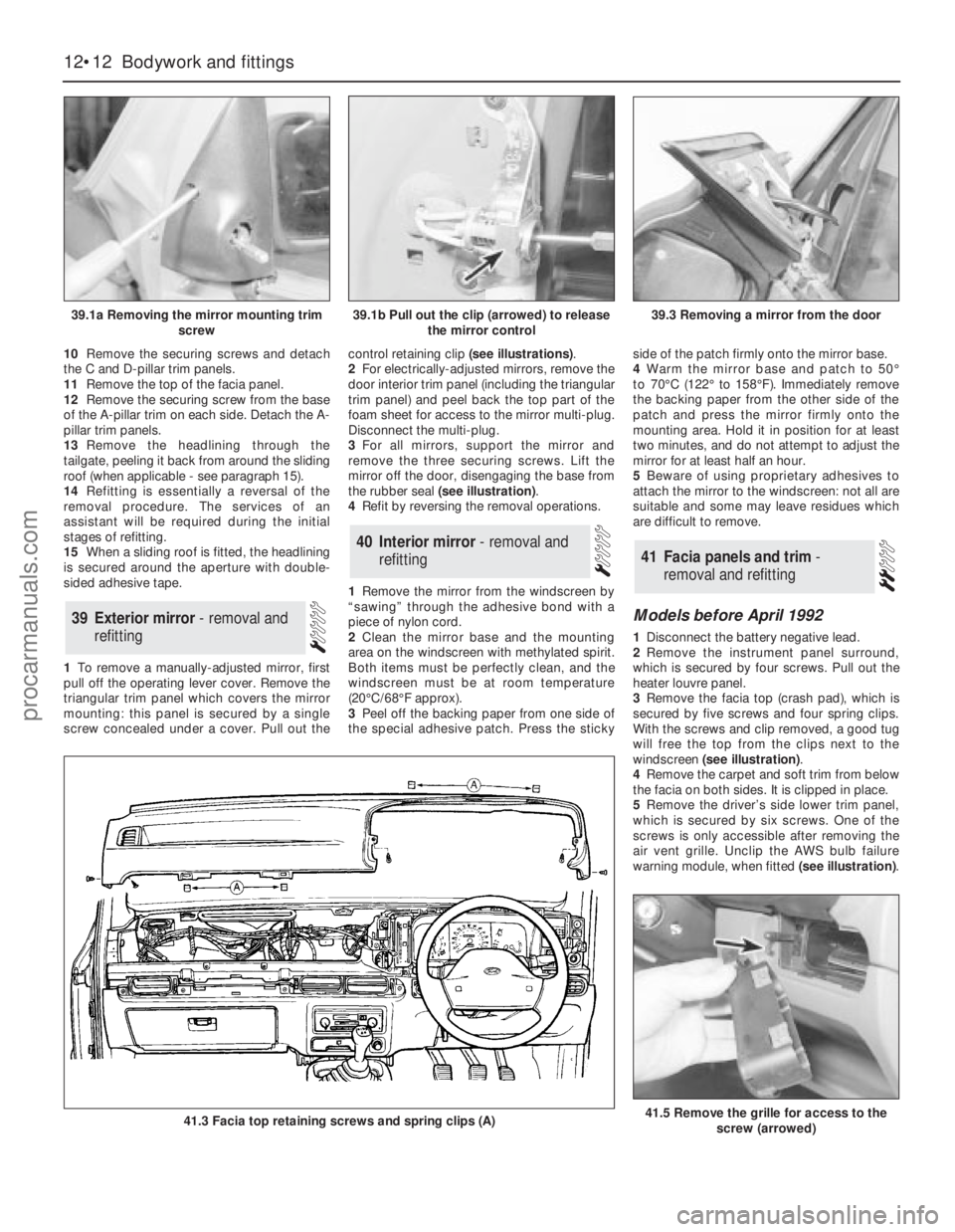
3Remove the facia top (crash pad), which is
secured by five screws and four spring clips.
With the screws and clip removed, a good tug
will free the top from the clips next to the
windscreen (see illustration).
4Remove the carpet and soft trim from below
the facia on both sides. It is clipped in place.
5Remove the driver’s side lower trim panel,
which is secured by six screws. One of the
screws is only accessible after removing the
air vent grille. Unclip the AWS bulb failure
warning module, when fitted (see illustration).
41Facia panels and trim -
removal and refitting40Interior mirror - removal and
refitting
39Exterior mirror - removal and
refitting
12•12Bodywork and fittings
39.1a Removing the mirror mounting trim
screw
41.3 Facia top retaining screws and spring clips (A)41.5 Remove the grille for access to the
screw (arrowed)
39.1b Pull out the clip (arrowed) to release
the mirror control39.3 Removing a mirror from the door
procarmanuals.com
Page 170 of 255
6Disconnect the glovebox arms and hinges.
Withdraw the hinge pins and remove the lid.
7Slide the auxiliary fuse panel off its
mounting and remove the glovebox light
(when fitted).
8Remove the ABS and ESC/EEC modules
(Chapter 13). Remove the two nuts and
washers from inside the glovebox.
9Remove the radio, stowage box or graphic
equaliser, ashtray, cigarette lighter panel and
(when applicable) the gear lever gaiter.
10Remove the centre console, disconnecting
switches, rear heater controls etc as
necessary.
11Remove the six screws which secure the
passenger’s side lower panel. Remove the
panel. 12Refit by reversing the removal operations,
transferring the brackets, captive nuts or other
fittings to any new panels being fitted.
Models from April 1992
13Disconnect the battery negative terminal.
14Remove the centre console.
15Remove the radio, amplifier unit and
(where necessary) the CD player.
16Remove the instrument cluster.
17Remove the steering wheel and then the
steering column direction indicator/headlight
flasher switch and windscreen wipe/wash
switch.
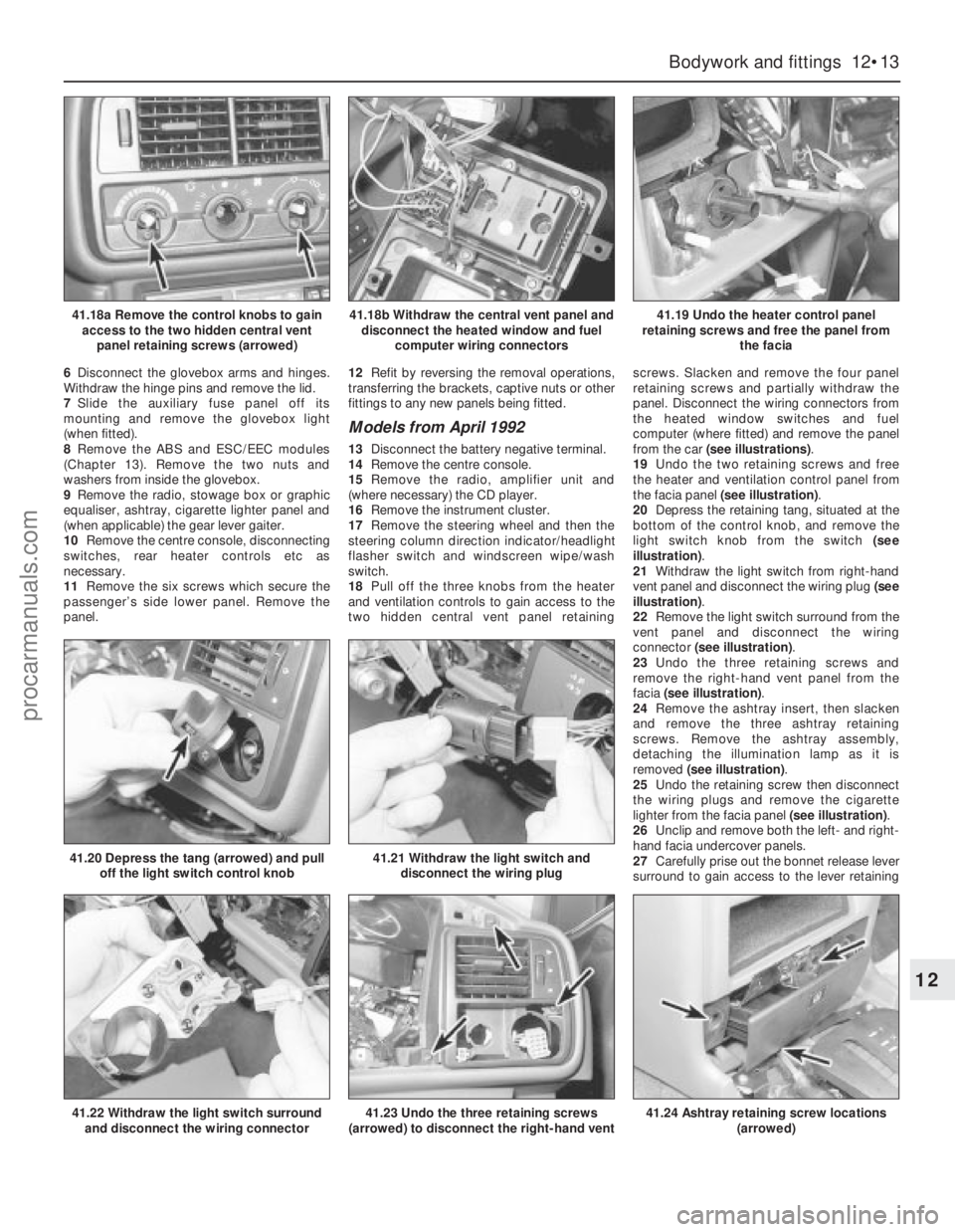
18Pull off the three knobs from the heater
and ventilation controls to gain access to the
two hidden central vent panel retainingscrews. Slacken and remove the four panel
retaining screws and partially withdraw the
panel. Disconnect the wiring connectors from
the heated window switches and fuel
computer (where fitted) and remove the panel
from the car (see illustrations).
19Undo the two retaining screws and free
the heater and ventilation control panel from
the facia panel (see illustration).
20Depress the retaining tang, situated at the
bottom of the control knob, and remove the
light switch knob from the switch (see
illustration).
21Withdraw the light switch from right-hand
vent panel and disconnect the wiring plug (see
illustration).
22Remove the light switch surround from the
vent panel and disconnect the wiring
connector (see illustration).
23Undo the three retaining screws and
remove the right-hand vent panel from the
facia (see illustration).
24Remove the ashtray insert, then slacken
and remove the three ashtray retaining
screws. Remove the ashtray assembly,
detaching the illumination lamp as it is
removed (see illustration).
25Undo the retaining screw then disconnect
the wiring plugs and remove the cigarette
lighter from the facia panel (see illustration).
26Unclip and remove both the left- and right-
hand facia undercover panels.
27Carefully prise out the bonnet release lever
surround to gain access to the lever retaining
Bodywork and fittings 12•13
12
41.18a Remove the control knobs to gain
access to the two hidden central vent
panel retaining screws (arrowed)41.18b Withdraw the central vent panel and
disconnect the heated window and fuel
computer wiring connectors41.19 Undo the heater control panel
retaining screws and free the panel from
the facia
41.22 Withdraw the light switch surround
and disconnect the wiring connector
41.20 Depress the tang (arrowed) and pull
off the light switch control knob41.21 Withdraw the light switch and
disconnect the wiring plug
41.23 Undo the three retaining screws
(arrowed) to disconnect the right-hand vent41.24 Ashtray retaining screw locations
(arrowed)
procarmanuals.com
Page 171 of 255
12•14Bodywork and fittings
41.25 Withdraw the cigarette lighter and
disconnect the wiring plugs
41.30 Removing the passenger side lower
kick panel
41.29a Lift the glovebox hinge retaining
clips and disconnect the hinge arms41.29b Withdraw the glovebox noting the
plastic bushes (arrowed) which are fitted to
the pivot bolts
41.29c Withdraw the glovebox illumination
light and disconnect the wiring connector
41.28 Undo the five right-hand lower facia
panel retaining screws (arrowed)
41.31a A-pillar trim panel retaining clip . . .
41.31b . . . and lower locating tab (viewed
through windscreen)
41.27a Remove the three bonnet release
lever retaining screws (arrowed)41.27b Withdraw the bonnet release lever
and disconnect it from the operating cable
41.32 Disconnect the alarm warning LED
wiring connector41.33 Removing the windscreen vent panel
(viewed through the windscreen)
procarmanuals.com
Page 172 of 255
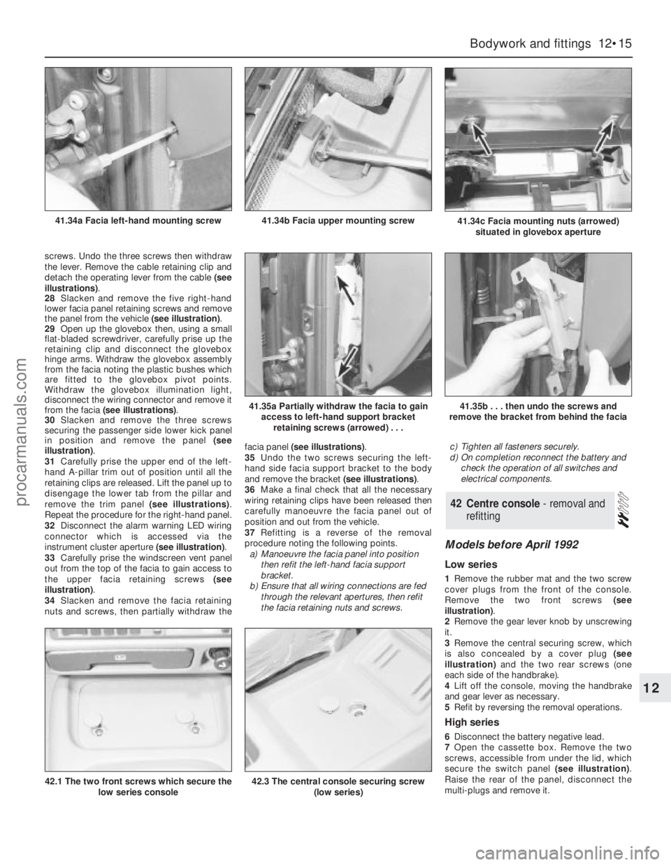
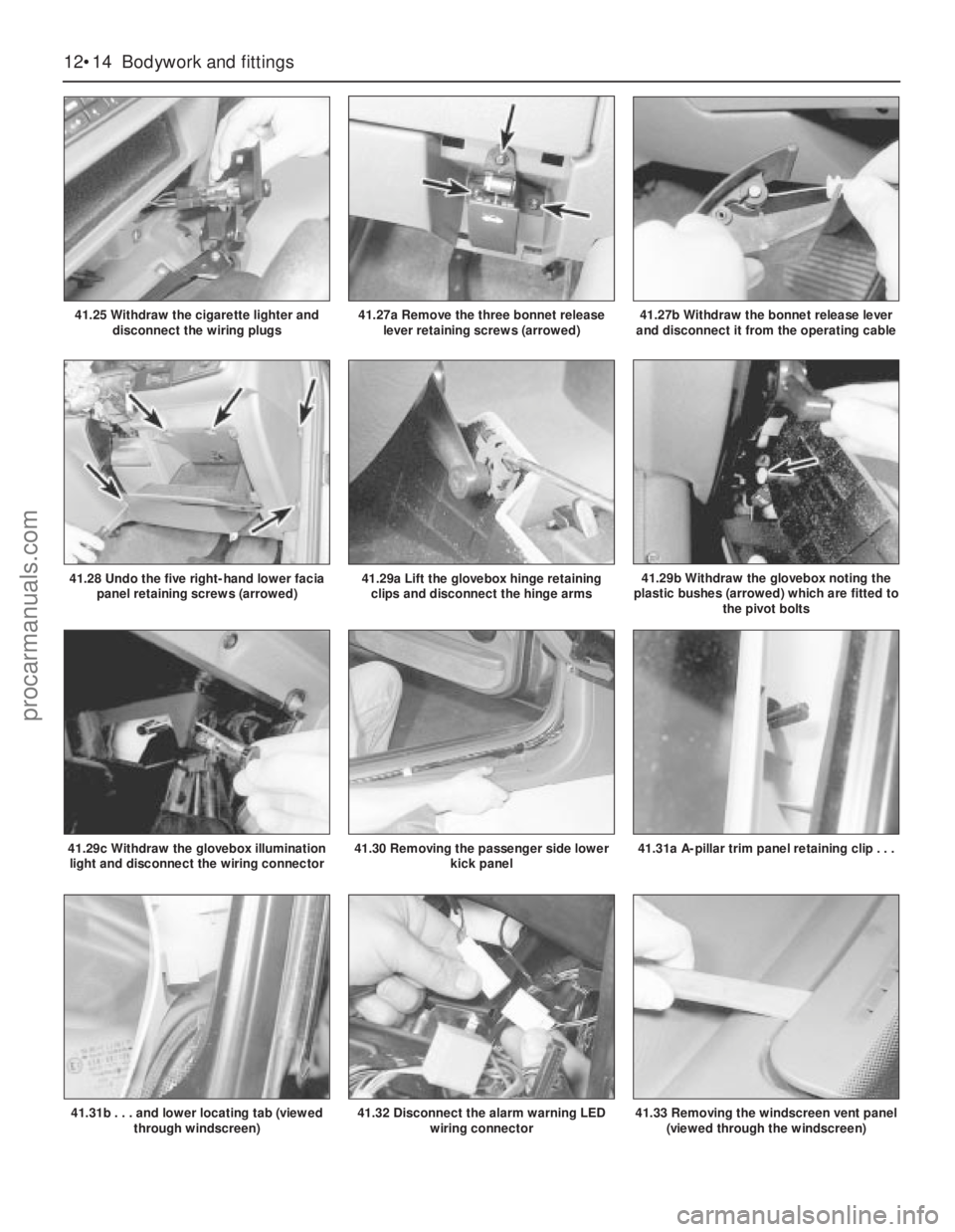
screws. Undo the three screws then withdraw
the lever. Remove the cable retaining clip and
detach the operating lever from the cable (see
illustrations).
28Slacken and remove the five right-hand
lower facia panel retaining screws and remove
the panel from the vehicle (see illustration).
29Open up the glovebox then, using a small
flat-bladed screwdriver, carefully prise up the
retaining clip and disconnect the glovebox
hinge arms. Withdraw the glovebox assembly
from the facia noting the plastic bushes which
are fitted to the glovebox pivot points.
Withdraw the glovebox illumination light,
disconnect the wiring connector and remove it
from the facia (see illustrations).
30Slacken and remove the three screws
securing the passenger side lower kick panel
in position and remove the panel (see
illustration).
31Carefully prise the upper end of the left-
hand A-pillar trim out of position until all the
retaining clips are released. Lift the panel up to
disengage the lower tab from the pillar and
remove the trim panel (see illustrations).
Repeat the procedure for the right-hand panel.
32Disconnect the alarm warning LED wiring
connector which is accessed via the
instrument cluster aperture (see illustration).
33Carefully prise the windscreen vent panel
out from the top of the facia to gain access to
the upper facia retaining screws (see
illustration).
34Slacken and remove the facia retaining
nuts and screws, then partially withdraw thefacia panel (see illustrations).
35Undo the two screws securing the left-
hand side facia support bracket to the body
and remove the bracket (see illustrations).
36Make a final check that all the necessary
wiring retaining clips have been released then
carefully manoeuvre the facia panel out of
position and out from the vehicle.
37Refitting is a reverse of the removal
procedure noting the following points.
a)Manoeuvre the facia panel into position
then refit the left-hand facia support
bracket.
b)Ensure that all wiring connections are fed
through the relevant apertures, then refit
the facia retaining nuts and screws.c)Tighten all fasteners securely.
d)On completion reconnect the battery and
check the operation of all switches and
electrical components.
Models before April 1992
Low series
1Remove the rubber mat and the two screw
cover plugs from the front of the console.
Remove the two front screws (see
illustration).
2Remove the gear lever knob by unscrewing
it.
3Remove the central securing screw, which
is also concealed by a cover plug (see
illustration)and the two rear screws (one
each side of the handbrake).
4Lift off the console, moving the handbrake
and gear lever as necessary.
5Refit by reversing the removal operations.
High series
6Disconnect the battery negative lead.
7Open the cassette box. Remove the two
screws, accessible from under the lid, which
secure the switch panel (see illustration).
Raise the rear of the panel, disconnect the
multi-plugs and remove it.
42Centre console - removal and
refitting
Bodywork and fittings 12•15
12
41.34c Facia mounting nuts (arrowed)
situated in glovebox aperture41.34b Facia upper mounting screw41.34a Facia left-hand mounting screw
41.35a Partially withdraw the facia to gain
access to left-hand support bracket
retaining screws (arrowed) . . .41.35b . . . then undo the screws and
remove the bracket from behind the facia
42.1 The two front screws which secure the
low series console42.3 The central console securing screw
(low series)
procarmanuals.com
Page 173 of 255
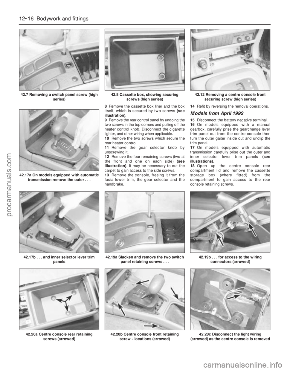
8Remove the cassette box liner and the box
itself, which is secured by two screws (see
illustration).
9Remove the rear control panel by undoing the
two screws in the top corners and pulling off the
heater control knob. Disconnect the cigarette
lighter, and other wiring when applicable.
10Remove the two screws which secure the
rear heater control.
11Remove the gear selector knob by
unscrewing it.
12Remove the four remaining screws (two at
the front and one on each side) (see
illustration). It may be necessary to cut the
carpet to gain access to the side screws.
13Remove the console, freeing it from the
facia lower trim, the gear selector and the
handbrake.14Refit by reversing the removal operations.
Models from April 1992
15Disconnect the battery negative terminal.
16On models equipped with a manual
gearbox, carefully prise the gearchange lever
trim panel out from the centre console then
turn the outer gaiter inside out and unclip the
trim panel.
17On models equipped with automatic
transmission carefully prise out the outer and
inner selector lever trim panels (see
illustrations).
18Open up the centre console rear
compartment lid and remove the cassette
storage box (where fitted) from the
compartment to gain access to the rear
console retaining screws.
12•16Bodywork and fittings
42.7 Removing a switch panel screw (high
series)
42.20a Centre console rear retaining
screws (arrowed)
42.17b . . . and inner selector lever trim
panels
42.17a On models equipped with automatic
transmission remove the outer . . .
42.19a Slacken and remove the two switch
panel retaining screws . . .42.19b . . . for access to the wiring
connectors (arrowed)
42.20b Centre console front retaining
screw - locations (arrowed)42.20c Disconnect the light wiring
(arrowed) as the centre console is removed
42.8 Cassette box, showing securing
screws (high series)42.12 Removing a centre console front
securing screw (high series)
procarmanuals.com
Page 174 of 255
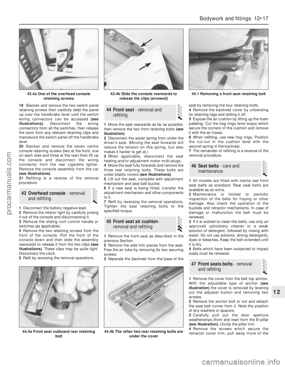
19Slacken and remove the two switch panel
retaining screws then carefully slide the panel
up over the handbrake lever until the switch
wiring connectors can be accessed (see
illustrations). Disconnect the wiring
connectors from all the switches, then release
the loom from any relevant retaining clips and
manoeuvre the switch panel off the handbrake
lever.
20Slacken and remove the seven centre
console retaining screws (two at the front, one
on each side and three at the rear) then lift up
the console and disconnect the wiring
connector from the rear cigarette lighter.
Remove the console assembly from the car
(see illustrations).
21Refitting is a reverse of the removal
procedure.
1Disconnect the battery negative lead.
2Remove the interior light by carefully prising
it out of the console and disconnecting it.
3Remove the sliding roof control handle or
switches (as applicable).
4Remove the two retaining screws from the
front of the console. Pull the front of the
console down and then slide the assembly
rearwards to release it from the two clips (see
illustrations). These clips may be quite tight.
Disconnect the clock.
5Refit by reversing the removal operations.1Move the seat rearwards as far as possible,
then remove the two front retaining bolts (see
illustration).
2Disconnect the assist spring from under the
driver’s seat. (Moving the seat forwards will
reduce the tension on this spring, but also
makes it harder to get at.)
3When applicable, disconnect the seat
heating and/or adjustment motor multi-plugs.
4Move the seat fully forwards and remove the
three rear retaining bolts. These bolts are
under plastic covers (see illustrations).
5Lift out the seat, complete with adjustment
mechanism and seat belt buckle.
6If a new seat is being fitted, transfer the
adjustment mechanism and other components
to it.
7Refit by reversing the removal operations.
Tighten the seat retaining bolts to the
specified torque.
1Remove the front seat as described in the
previous Section.
2Remove the side trim pieces from the seat.
Free the air tube by removing Its two securing
screws.
3Separate the backrest from the base of theseat by removing the four retaining bolts.
4Remove the backrest cover by unbending
its retaining tags and sliding it off.
5Expose the air cushion by lifting up the foam
padding. Cut the hog rings (wire loops) which
secure the corners of the cushion and remove
it with the air hoses.
6When refitting, use new hog rings. Position
the cut-out in the cushion level with the
second spring in the backrest.
7The remainder of refitting is a reversal of the
removal procedure.
1All models are fitted with inertia reel front
seat belts as standard. Rear seat belts are
available as an extra.
2Maintenance is limited to periodic
inspection of the belts for fraying or other
damage. Also check the operation of the
buckles and retractor mechanisms. In case of
damage or malfunction the belt must be
renewed.
3If it is wished to clean the belts, use only an
approved upholstery cleaner or a weak
solution of detergent, followed by rinsing with
water. Do not use solvents, strong detergents,
dyes or bleaches. Keep the belt extended until
it is dry.
4Belts which have been subjected to impact
loads must be renewed.
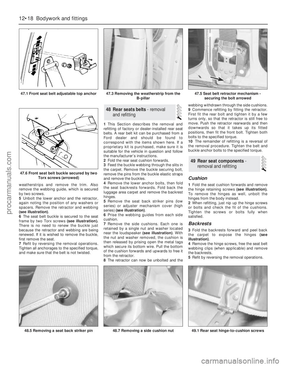
1Remove the cover from the belt top anchor.
With the adjustable type of anchor(see
illustration)the cover is removed by levering
out the adjuster button and removing two
screws.
2Remove the anchor bolt or nut and detach
the seat belt runner from it. Note the position
of any washers or spacers.
3Carefully pull out the door aperture
weatherstrips (front and rear) from the B-pillar
(see illustration). Unclip the pillar trim.
4Remove the screws which secure the
retractor cover trim, pull away more of the
47Front seats belts - removal
and refitting
46Seat belts - care and
maintenance
45Front seat air cushion -
removal and refitting
44Front seat - removal and
refitting
43Overhead console - removal
and refitting
Bodywork and fittings 12•17
12
43.4a One of the overhead console
retaining screws43.4b Slide the console rearwards to
release the clips (arrowed)44.1 Removing a front seat retaining bolt
44.4a Front seat outboard rear retaining
bolt44.4b The other two rear retaining bolts are
under the cover
procarmanuals.com
Page 175 of 255
weatherstrips and remove the trim. Also
remove the webbing guide, which is secured
by two screws.
5Unbolt the lower anchor and the retractor,
again noting the position of any washers or
spacers. Remove the retractor and webbing
(see illustration).
6The seat belt buckle is secured to the seat
frame by two Torx screws(see illustration).
There is no need to renew the buckle just
because the retractor and webbing are being
renewed. If it is wished to remove the buckle,
first remove the seat.
7Refit by reversing the removal operations.
Tighten all anchorages to the specified torque,
and make sure that the belt is not twisted.1This Section describes the removal and
refitting of factory or dealer-installed rear seat
belts. A rear belt kit can be purchased from a
Ford dealer and should be found to
correspond with the items shown here. If a
proprietary kit is purchased, make sure it is
suitable for the vehicle in question and follow
the manufacturer’s instructions.
2Fold the rear seat cushion forwards.
3Feed the buckle webbing through the slits in
the carpet. Remove the buckle securing bolt,
remove the pins from the buckle elastic straps
and remove the buckles.
4Remove the lower anchor bolts, then fold
the seat backrests forwards. Fold back the
luggage area carpet and remove the backrest
hinges.
5Remove the seat back striker pins (low
series) or adjuster mechanism cover (high
series) (see illustration).
6Prise the webbing guides from each side
cushion.
7Remove the side cushions. Each one is
retained by a single nut and washer located
near the loudspeaker (see illustration). With
the nut and washer removed, the cushion is
then released by prising open the metal tags
which secure its bottom wire. Pull the bottom
of the cushion forwards and upwards to free it
from the retractor.
8The retractor can now be unbolted and thewebbing withdrawn through the side cushions.
9Commence refitting by fitting the retractor.
First fit the rear bolt and tighten it by a few
turns only, so that the retractor is still free to
move. Push the retractor rearwards and then
downwards so that it takes up its fitted
positions, then fit the front bolt. Tighten both
bolts to the specified torque.
10The remainder of refitting is a reversal of
the removal procedure. Tighten the belt and
buckle anchor bolts to the specified torque.
Cushion
1Fold the seat cushion forwards and remove
the hinge retaining screws (see illustration).
To remove the hinges as well, unbolt the
hinges from the body instead.
2When refitting, just nip up the hinge screws
or bolts and check the fit of the cushions.
Tighten the screws or bolts fully when
satisfied.
Backrests
3Fold the backrests forward and peel back
the carpet to expose the hinges (see
illustration).
4Remove the hinge screws, free the seat belt
webbing clips (when applicable) and remove
the backrests.
5Refit by reversing the removal operations.
49Rear seat components -
removal and refitting
48Rear seats belts - removal
and refitting
12•18Bodywork and fittings
47.1 Front seat belt adjustable top anchor
47.6 Front seat belt buckle secured by two
Torx screws (arrowed)
48.5 Removing a seat back striker pin49.1 Rear seat hinge-to-cushion screws48.7 Removing a side cushion nut
47.3 Removing the weatherstrip from the
B-pillar47.5 Seat belt retractor mechanism -
securing the bolt arrowed
procarmanuals.com
Page 176 of 255
Backrest catch
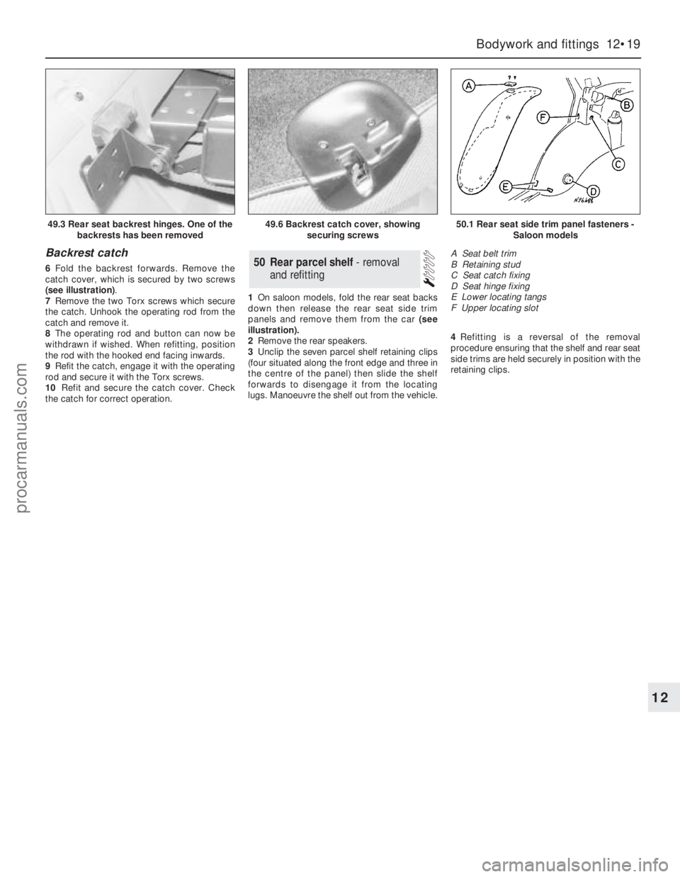
6Fold the backrest forwards. Remove the
catch cover, which is secured by two screws
(see illustration).
7Remove the two Torx screws which secure
the catch. Unhook the operating rod from the
catch and remove it.
8The operating rod and button can now be
withdrawn if wished. When refitting, position
the rod with the hooked end facing inwards.
9Refit the catch, engage it with the operating
rod and secure it with the Torx screws.
10Refit and secure the catch cover. Check
the catch for correct operation.1On saloon models, fold the rear seat backs
down then release the rear seat side trim
panels and remove them from the car (see
illustration).
2Remove the rear speakers.
3Unclip the seven parcel shelf retaining clips
(four situated along the front edge and three in
the centre of the panel) then slide the shelf
forwards to disengage it from the locating
lugs. Manoeuvre the shelf out from the vehicle.4Refitting is a reversal of the removal
procedure ensuring that the shelf and rear seat
side trims are held securely in position with the
retaining clips.50Rear parcel shelf - removal
and refitting
Bodywork and fittings 12•19
12
49.3 Rear seat backrest hinges. One of the
backrests has been removed49.6 Backrest catch cover, showing
securing screws50.1 Rear seat side trim panel fasteners -
Saloon models
A Seat belt trim
B Retaining stud
C Seat catch fixing
D Seat hinge fixing
E Lower locating tangs
F Upper locating slot
procarmanuals.com
 1
1 2
2 3
3 4
4 5
5 6
6 7
7 8
8 9
9 10
10 11
11 12
12 13
13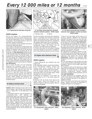 14
14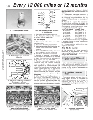 15
15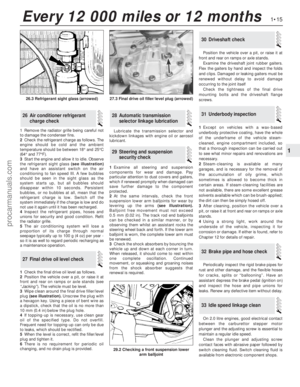 16
16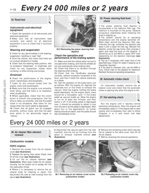 17
17 18
18 19
19 20
20 21
21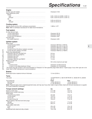 22
22 23
23 24
24 25
25 26
26 27
27 28
28 29
29 30
30 31
31 32
32 33
33 34
34 35
35 36
36 37
37 38
38 39
39 40
40 41
41 42
42 43
43 44
44 45
45 46
46 47
47 48
48 49
49 50
50 51
51 52
52 53
53 54
54 55
55 56
56 57
57 58
58 59
59 60
60 61
61 62
62 63
63 64
64 65
65 66
66 67
67 68
68 69
69 70
70 71
71 72
72 73
73 74
74 75
75 76
76 77
77 78
78 79
79 80
80 81
81 82
82 83
83 84
84 85
85 86
86 87
87 88
88 89
89 90
90 91
91 92
92 93
93 94
94 95
95 96
96 97
97 98
98 99
99 100
100 101
101 102
102 103
103 104
104 105
105 106
106 107
107 108
108 109
109 110
110 111
111 112
112 113
113 114
114 115
115 116
116 117
117 118
118 119
119 120
120 121
121 122
122 123
123 124
124 125
125 126
126 127
127 128
128 129
129 130
130 131
131 132
132 133
133 134
134 135
135 136
136 137
137 138
138 139
139 140
140 141
141 142
142 143
143 144
144 145
145 146
146 147
147 148
148 149
149 150
150 151
151 152
152 153
153 154
154 155
155 156
156 157
157 158
158 159
159 160
160 161
161 162
162 163
163 164
164 165
165 166
166 167
167 168
168 169
169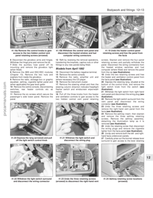 170
170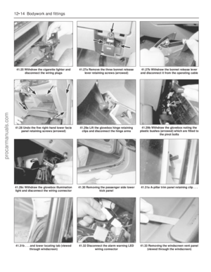 171
171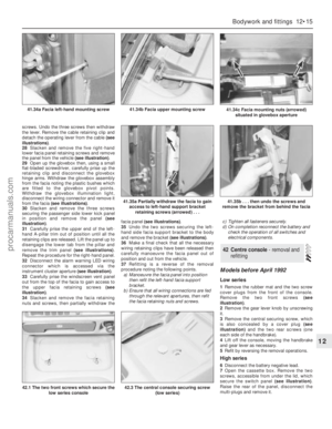 172
172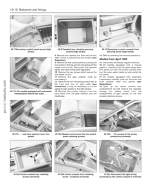 173
173 174
174 175
175 176
176 177
177 178
178 179
179 180
180 181
181 182
182 183
183 184
184 185
185 186
186 187
187 188
188 189
189 190
190 191
191 192
192 193
193 194
194 195
195 196
196 197
197 198
198 199
199 200
200 201
201 202
202 203
203 204
204 205
205 206
206 207
207 208
208 209
209 210
210 211
211 212
212 213
213 214
214 215
215 216
216 217
217 218
218 219
219 220
220 221
221 222
222 223
223 224
224 225
225 226
226 227
227 228
228 229
229 230
230 231
231 232
232 233
233 234
234 235
235 236
236 237
237 238
238 239
239 240
240 241
241 242
242 243
243 244
244 245
245 246
246 247
247 248
248 249
249 250
250 251
251 252
252 253
253 254
254

